Communication
Networks
Sharam Hekmat
Contents
Contents 6
Preface 10
1. Introduction 1
1.1. Network Components 2
1.2. Network Types 2
1.3. The OSI Model 4
1.3.1. The Physical Layer 7
1.3.2. The Data Link Layer 7
1.3.3. The Network Layer 8
1.3.4. The Transport Layer 9
1.3.5. The Session Layer 9
1.3.6. The Presentation Layer 10
1.3.7. The Application Layer 10
1.4. Protocol Notations 11
1.4.1. Service Primitives 11
1.4.2. Sequence Diagrams 12
1.4.3. State Transition Diagrams 12
1.5. Standards 13
1.6. Further Reading 14
1.7. Summary 15
1.8. Exercises 16
2. The Physical Layer 18
2.1. Equipment 19
2.1.1. Equipment Types 19
2.1.2. Connection Types 19
2.2. Transmission 20
2.2.1. Signal Types 20
2.2.2. Modulation 21
2.2.3. Digitization 22
2.2.4. Synchronization 23
2.2.5. Transmission Media 24
2.3. Multiplexing 27
2.3.2. Frequency Division Multiplexing (FDM) 28 2.3.3. Time Division Multiplexing (TDM) 29
2.3.4. Concentration 29
2.4. Physical Layer Standards 30
2.4.1. RS-232 30
2.4.2. CCITT X.21 32
2.5. Further Reading 33
2.6. Summary 33
2.7. Exercises 34
3. The Data Link Layer 36
3.1 Link Protocol Types 37
3.1.1. Synchronous Protocols 37
3.1.2. Asynchronous Protocols 38
3.1.3. Master-Slave Protocols 38
3.1.4. Peer-to-Peer Protocols 38
3.2. Link Protocol Functions 38
3.2.1. Acknowledgments 39
3.2.2. Timers 39
3.2.3. Error Checking 40
3.2.4. Retransmission 42
3.2.5. Flow Control 42
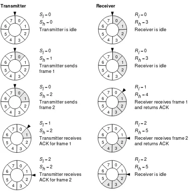
3.3. Sliding Window Protocol 43
3.4. Data Link Layer Standards 45
3.4.1. BSC 45
3.4.2. HDLC 46
3.5. Further Reading 48
3.6. Summary 49
3.7. Exercises 50
4. The Network Layer 52
4.1. Network Services 53
4.2. Switching Methods 55
4.2.1. Circuit Switching 55
4.2.2. Packet Switching 57
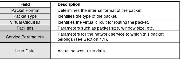
4.3. Packet Handling 59
4.3.1. Packet Structure 60
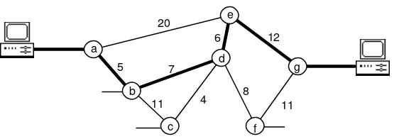
4.3.2. Routing 60
4.3.3. Congestion Control 63
4.3.4. Error Handling 63
4.4. Internetworking 64
4.5. Network Layer Standards 66
4.5.1. CCITT X.25 66
4.5.2. CCITT X.75 69
4.5.3. IP 70
4.5.4. ISO 8473 71
4.6. Further Reading 72
4.7. Summary 72
5. The Transport Layer 65
5.1. Transport Services 65
5.1.1. Network Types 67
5.2. Transport Protocol 67
5.2.1. TPDUs 67
5.2.2. Classes of Protocol 68
5.2.3. Segmentation 69
5.2.4. Multiplexing 69
5.2.5. Splitting and Recombining 69
5.2.6. Addressing 69
5.2.7. Flow Control 70
5.2.8. Error Checking 70
5.3. Transport Layer Standards 70
5.3.1. TCP 71
5.4. Further Reading 72
6. The Session Layer 74
6.1. Session Services 74
6.1.1. Session Layer Role 77
6.1.2. Functional Units 77
6.2. Session Protocol 78
6.2.1. Tokens 79
6.2.2. Activities and Dialogue Units 79
6.2.3. Synchronization 80
6.2.4. Error Reporting and Resynchronization 81
6.2.5. SPDUs 82
6.3. Session Layer Standards 82
6.4. Further Reading 83
7. The Presentation Layer 84
7.1. Presentation Services 84
7.1.1. Syntax 84
7.1.2. Service Primitives 87
7.1.3. Functional Units 89
7.2.1. Definitions in ASN.1 89
7.2.2. Basic Encoding Rules 91
7.3. Presentation Protocol 93
7.4. Presentation Standards 94
7.5. Further Reading 94
8. The Application Layer 95
8.1. Application Services 95
8.1.1. Application Entity 96
8.2. Common Application Service Elements 97
8.2.1. Association Control 97
8.2.2. Reliable Transfer 97
8.2.3. Remote Operations 98
8.3. Specific Application Service Elements 98
8.3.1. Virtual Terminal 98
8.3.2. Message Handling Systems 100
8.3.3. File Transfer, Access, and Management 104
8.4. Other Standards 108
8.5. Further Reading 108
9. Local Area Networks 109
9.1. Basic Concepts 109
9.1.1. Topologies and Access Protocols 110
9.1.2. Architecture 112
9.1.3. Transmission 113
9.2. IEEE 802 Standards 113
9.2.1. Logical Link Control 114
9.2.2. CSMA/CD 115
9.2.3. Token Bus 116
9.2.4. Token Ring 117
9.3. ANSI FDDI Standard 118
9.3.1. Topology 118
9.3.2. Token Ring Protocol 119
9.4. Further Reading 120
10. Telephone Networks 121
10.1. Basic Concepts 121
10.1.1. A Simple Network 122
10.1.2. Networks Topologies 123
10.1.3. Switching Systems 125
10.2. Signaling 126
10.2.1. Subscriber Signaling 127
10.2.3. Common Channel Signaling 129
10.3. Signaling System Number 7 131
10.3.1. Signaling Data Link 132
10.3.2. Signaling Link Control 132
10.3.3. Signaling Network Functions 133 10.3.4. Signaling Connection Control Part 134
10.3.5. User Parts 135
10.3.6. Operations and Maintenance Applications Part 136
10.4. Private Telephone Networks 136
10.4.1. PBX Networks 136
10.4.2. Corporate Networks 137
10.4.3. Intelligent Networks 138
10.5. Further Reading 139
11. Integrated Services Digital Network 140
11.1. Basic Concepts 140
11.1.1. ISDN Channels 141
11.1.2. Functional Groupings and Reference Points 142
11.1.3. ISDN Services 144
11.2. Protocol Architecture 145
11.2.1. The Physical Layer 146
11.2.2. The Data Link Layer 148
11.2.3. The Network Layer 151
11.3. Frame Relay 154
11.3.1. V.120 155
11.3.2. Frame Relay 156
11.4. Internetworking 157
11.5. ISDN Standards 158
11.6. Further Reading 159
12. Broadband ISDN and ATM 161
12.1. Broadband ISDN 161
12.1.1. B-ISDN Services 161
12.1.2. B-ISDN User-Network Interface 163 12.1.3. B-ISDN Protocol Architecture 164
12.2. Asynchronous Transfer Mode 165
12.2.1. Channels and Paths 165
12.2.2. ATM Cells 167
12.3. Physical Layer 168
12.3.1. SDH-Based Interface 168
12.3.2. Cell-Based Interface 169
12.3.4. HEC Generation and Verification 171
12.3.5. Cell Rate Decoupling 171
12.4. ATM Layer 172
12.4.1. Generic Flow Control 172
12.4.2. Virtual Path Identifier 172
12.4.3. Virtual Channel Identifier 172
12.4.4. Payload Type 173
12.4.5. Cell Loss Priority 173
12.5. ATM Adaptation Layer 173
12.5.1. Segmentation and Reassembly Sublayer 174
12.5.2. Convergence Sublayer 175
12.6. B-ISDN Standards 175
12.7. Further Reading 175
Preface
This book is concerned with post-computer communication networks and two of its important streams: data communication and telecommunication. Data communication refers to the communication between digital computers, facilitated by computer networks. Telecommunication refers to the primarily human-to-human communication facilitated by the global telephone system. The differences between these two streams are mainly due to historical reasons. Telecommunication is increasingly relying on digital computer technology, and data communication is relying more than ever on telecommunication networks. The two streams are rapidly converging.
Newcomers to this field are often bewildered by the substantial wealth of information already published on the subject. This book is aimed at this group of people. It provides a broad coverage of the key concepts, techniques, and terminology, so as to prepare readers for more advanced discussions. In-depth discussions of technically-involved topics are intentionally avoided in favor of more general concepts. No previous knowledge of networks or programming is assumed.
1.
Introduction
A computer network is the infrastructure that allows two or more computers (called hosts) to communicate with each other. The network achieves this by providing a set of rules for communication, called protocols, which should be observed by all participating hosts. The need for a protocol should be obvious: it allows different computers from different vendors and with different operating characteristics to ‘speak the same language’.
This chapter introduces the fundamental concepts of computer networks. We will first look at constituent network components and various network types, and then describe a reference model for network protocol architectures which we will expand upon throughout the rest of this book. We will also discuss the role of international standards and major standards organizations.
After reading this chapter you should be able to:
• Describe the general characteristics of a computer network.
• Understand the role of the major components of a computer network.
• Distinguish between different network types and understand their properties.
• Appreciate the relevance and importance of standards, in general, and the OSI model, in particular.
• Describe the role and functions of each of the OSI layers.
• Use sequence and state transition diagrams to interpret and describe protocols.
1.1.
Network Components
Figure 1.1 shows an abstract view of a network and its hosts. The network is made up of two types of components: nodes and communication lines. The nodes typically handle the network protocols and provide switching capabilities. A node is usually itself a computer (general or special) which runs specific network software. The communication lines may take many different shapes and forms, even in the same network. Examples include: copper wire cables, optical fiber, radio channels, and telephone lines.
A host is connected to the network by a separate communication line which connects it to one of the nodes. In most cases, more than one host may be connected to the same node. From a host’s point of view, the entire network may be viewed as a black box, to which many other hosts are connected. Each host has a unique address allocated to it by the network. For a host to communicate with another host, it needs to know the latter’s address. All communication between hosts passes through the nodes, which in turn determine how to route messages across the network, from one point to another.
Figure 1.1 An abstract network.
nodes
hosts network
Throughout the rest of this book, there will be occasions when it is not necessary to distinguish between hosts and nodes. In such cases, we will use the term station to mean either.
1.2.
Network Types
Networks may be divided into different types and categories according to four different criteria:
Network (LAN). LANs are typically used to connect a set of hosts within the same building (e.g., an office environment) or a set of closely-located buildings (e.g., a university campus). For larger distances, the network is said to be a Metropolitan Area Network (MAN) or a Wide Area Network (WAN). MANs cover distances of up to a few hundred kilometers and are used for inteconnecting hosts spread across a city. WANs are used to connect hosts spread across a country, a continent, or the globe. LANs, MANs, and WANs usually coexist: closely-located hosts are connected by LANs which can access hosts in other remote LANs via MANs and WANs, as illustrated in Figure 1.2.
2. Access restrictions.Most networks are for the private use of the organizations to which they belong; these are called private networks. Networks maintained by banks, insurance companies, airlines, hospitals, and most other businesses are of this nature. Public networks, on the other hand, are generally accessible to the average user, but may require registration and payment of connection fees. Internet is the most-widely known example of a public network. Technically, both private and public networks may be of LAN, MAN, or WAN type, although public networks, by their size and nature, tend to WANs.
Figure 1.2 Example of a WAN between LANs.
Perth
Darwin
Adelaide
Brisbane
Sydney
Melbourne WAN
LAN/MAN
across the network in order to get from one node to another. In the broadcast model, on the other hand, all nodes share the same communication medium and, as a result, a message transmitted by any node can be received by all other nodes. A part of the message (an address) indicates for which node the message is intended. All nodes look at this address and ignore the message if it does not match their own address.
Figure 1.3 Communication models.
point-to-point broadcast
4. Switching model employed by the nodes. In the point-to-point model, nodes either employ circuit switching or packet switching. Suppose that a host A wishes to communicate with another host B. In circuit switching, a dedicated communication path is allocated between A and B, via a set of intermediate nodes. The data is sent along the path as a continuous stream of bits. This path is maintained for the duration of communication between A and B, and is then released. In packet switching, data is divided into packets (chunks of specific length and characteristics) which are sent from A to B via intermediate nodes. Each intermediate node temporarily stores the packet and waits for the receiving node to become available to receive it. Because data is sent in packets, it is not necessary to reserve a path across the network for the duration of communication between A and B. Different packets can be routed differently in order to spread the load between the nodes and improve performance. However, this requires packets to carry additional addressing information.
1.3.
The OSI Model
The International Standards Organization (ISO) has developed a reference model for network design called the Open Systems Interconnection (OSI). It proposes a seven-layer architecture for networks, as summarized by Figure 1.4. Each layer is characterized by a set of standard protocols which specify its behavior.
Figure 1.4 The OSI reference model.
7 Application Message Mutually-agreeable meaning of application data (common semantics).
6 Presentation Message Mutually-agreeable binary representation of application data (common syntax).
5 Session Message Negotiation of the establishment and termination of connections (sessions).
4 Transport Message Efficient and cost-effective transportation of data across the network.
3 Network Packet Routing of data packets within the network and across multiple networks.
2 Data Link Frame Provision of a reliable communication line to the network layer.
1 Physical Bit Transmission of raw data bits over communication lines.
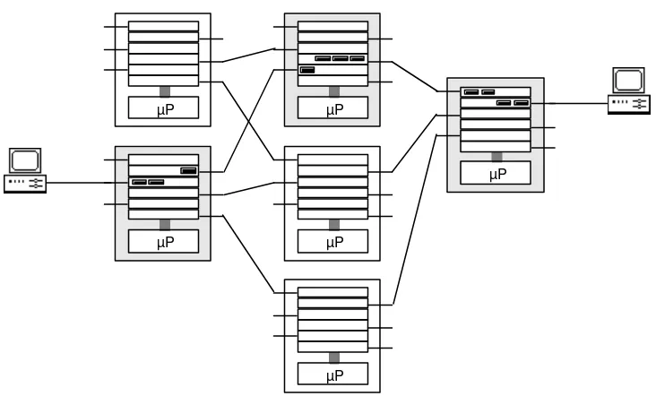
These seven layers represent the protocol architecture for the communications component of a host. The nodes in a network implement only the lower three layers, as illustrated in Figure 1.5. The reason for this is that the upper four layers are irrelevant to the task of communication between the nodes.
In Figure 1.5, when host A sends a message to host B, the message moves down the successive layers of host A, from the application layer to the presentation layer, to the session layer, etc., until it reaches the physical layer. It is then transmitted across the communication line between host A and node X, and moves up the three layers of node X and down again. Then it is transmitted to node Y where it goes through the same procedure, and finally is transmitted to host B, where it moves up its seven layers, until it arrives at the application layer of host B.
Figure 1.5 Nodes use only the lower 3 layers.
Application
Although actual communication takes place only at the physical layer, it is often useful to think of virtual communication between corresponding layers. For example, we can use an imaginary line of communication between the presentation layer on host A and the same layer on host B. This would be characterized by the
The terms protocol and layer are often used interchangeably. This is harmless but not entirely accurate. Strictly speaking, protocol refers to the rules and conventions that the functions of a layer should conform to. Layer refers to a set of services and functions and their realization in hardware or software. A layer is therefore characterized by its protocol. A set of network layers is also commonly referred to as a protocol stack.
Each of the seven layers of the OSI model hides the implementation details of the lower layers from the upper layers. Well-defined protocols and interfaces for each of the layers make it possible for the layer to be designed and implemented in isolation from the other layers. Except for the physical layer, which is implemented in hardware, all other layers are implemented in software.1 For example, each of these
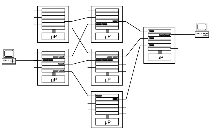
layers may be implemented as a set of routines which communicate with the layer above and the layer below it via parameters passed in function calls. Alternatively, each layer may be implemented as a task (in a multi-tasking environment) which communicates with other tasks by message passing. Figure 1.6 illustrates the latter.
Figure 1.6 OSI layers as software tasks.
Application
For house-keeping purposes, each layer adds an additional piece of information to the message it is transmitting. The same layer removes the additional piece of information on the receiving end. The additional information appears in form of a header (e.g., TH = Transport Header). The data link layer adds a header as well as a trailer to its data.
1 The Data Link layer is also often implemented in hardware for efficiency reasons. Custom chips are
Each of the seven layers of the OSI model is described below in more detail. Subsequent chapters examine the layers in greater depth and discuss their main protocols. It should be pointed out that the OSI model is not the only model in use. It is, however, the most-widely respected model and has become a standard benchmark for comparing other network architectures against.
1.3.1. The Physical Layer
The physical layer is concerned with the transmission of raw data bits over communication lines. Physical layer standards and protocols are concerned with issues such as the following:
• How a physical circuit is established between communicating devices.
• How the circuit is terminated when no longer needed.
• The physical form (e.g., voltages, frequencies, timing) in which data bits (binary values 0 and 1) are represented.
• Whether transmission of data can take place in one or both directions over the same physical connection.
• Characteristics of the physical media that carry the signals (e.g., copper wire, optical fiber, radio waves).
• Characteristics of the connectors used for connecting the physical media.
• How data from a number of sources should be multiplexed before transmission and demultiplexed upon arrival, and the type of multiplexing technique to be used.
• The type of modulation to be used for transmitting digital data over analog transmission lines.
The physical layer accounts for much of the tangible components of a network, including cables, satellites, earth stations, repeaters, multiplexers, concentrators, and modems. Physical layer protocols and standards are of mechanical, electrical, functional, and procedural nature.
The physical layer hides the above details from the higher layers. To the data link layer, it appears as a logical communication channel which can send a stream of bits from one point in the network to another (but not necessarily reliably).
1.3.2. The Data Link Layer
and checks for transmission errors by requiring the receiving end to send back acknowledgment frames. Data link protocols are concerned with the following issues:
• How to divide the data into frames.
• How to delimit frames by adding special bit patterns to the beginning and end of each frame. This allows the receiving end to detect where each frame begins and where it ends.
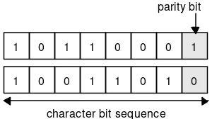
• Error detection. Some form of error check is included in the frame header. This is constructed by the transmitting end based on the contents of the frame, and checked for integrity by the receiving end. A change in the frame bits can be detected in this way.
• Error correction. When a frame arrives corrupted or is for any reason lost in the network, it is retransmitted. Lost acknowledgment frames may result in duplicate frames, which need to be detected and corrected as well.
• Flow control. In general, not all communication devices in a network operate at the same speed. Flow control provides a means of avoiding a slow receiver from being swamped by data from a fast transmitter.
The data link layer hides the above details from the higher layers. To the network layer, it appears as a reliable communication channel which can send and receive data packets as frames.
1.3.3. The Network Layer
The network layer is concerned with the routing of data across the network from one end to another. To do this, the network layer converts the data into packets and ensures that the packets are delivered to their final destination, where they can be converted back into the original data. Network layer protocols are concerned with the following issues:
• The interface between a host and the network.
• The interface between two hosts across the network.
• Routing of packets across the network, including the allocation of a route and handling of congestion.
• Correct ordering of packets to reflect the original order of data.
• Collection of statistical information (e.g., number of transmitted packets) for performance measurement and accounting purposes.
The network layer hides the above details from the higher layers. To the transport layer, it appears as a uniform data transfer service, regardless of the location of the communicating devices and how they are connected.
1.3.4. The Transport Layer
The aim of the transport layer is to isolate the upper three layers from the network, so that any changes to the network equipment technology will be confined to the lower three layers (i.e., at the node level). Transport layer protocols are concerned with the following issues:
• Establishment and termination of host-to-host connections.
• Efficient and cost-effective delivery of data across the network from one host to another.
• Multiplexing of data, if necessary, to improve use of network bandwidth, and demultiplexing at the other end.
• Splitting of data across multiple network connections, if necessary, to improve throughput, and recombining at the other end.
• Flow control between hosts.
• Addressing of messages to their corresponding connections. The address information appears as a part of the message header.
• Type of service to be provided to the session layer (e.g., free versus error-prone connections, whether messages should be delivered in the order received or not).
The transport layer hides the above details from the higher layers. To the session layer, it appears as a customized data transfer service between two hosts, isolating the underlying network technology from it.
1.3.5. The Session Layer
The session layer provides a structured means for data exchange between user processes on communicating hosts. Session layer protocols are concerned with the following issues:
• Negotiating the establishment of a connection (a session) between user processes on communicating hosts, and its subsequent termination. This includes the setting of various communication parameters for the session (e.g., synchronization and control).
• Recovery from interrupted transport connections, if necessary.
• Grouping of messages into a larger message, if necessary, so that the larger message becomes available at the destination only when its constituent messages have all been delivered successfully.
The session layer hides the above details from the higher layers. To the presentation layer, it appears as an organized communication service between user processes.
1.3.6. The Presentation Layer
The presentation layer provides a mutually-agreeable binary representation of the application data communicated between two user processes. Since there are many ways of encoding application data (e.g., integers, text) into binary data, agreement on a common representation is necessary. Presentation layer protocols are concerned with issues such as the following:
• Abstract representation of application data.
• Binary representation of application data.
• Conversion between the binary representation of application data and a common format for transmission between peer applications.
• Data compression to better utilize network bandwidth.
• Data encryption as a security measure.
The presentation layer hides the above details from the higher layers. To the application layer, it appears as a universal communication service between user processes, regardless of their system-specific idiosyncrasies, allowing them to converse in a common syntax.
1.3.7. The Application Layer
The application layer is concerned with the semantics of data, i.e., what the data means to applications. The application layer provides standards for supporting a variety of application-independent services. Examples include:
• Virtual terminal standards to allow applications to communicate with different types of terminals in a device-independent manner.
• Message handling system standards used for electronic mail.
• Transaction processing standards to allow different companies with different systems to access each other’s on-line databases (e.g., in banking and airline reservation).
• On-line directory standards for storing details of individuals, organizations, and network components.
• Standards for exchanging formatted documents.
Application layer standards have paved the way for open software systems, in which data can be communicated between incompatible base systems (i.e., different hardware and software architectures) without loss of meaning or usefulness.
1.4.
Protocol Notations
OSI network protocols are specified in a variety of notations. This section describes two popular notations, sequence diagrams and state transition diagrams, which are extensively used in standards and the literature. Both rely on the notion of a service primitive which is described first.
1.4.1. Service Primitives
A service primitive is an abstract representation of the interaction between a service provider and a service user. Service primitives are concerned with what
interactions take place rather than how such interactions are implemented. Service primitives may be of one of the following four types:
• Request Primitive. This is issued by a service user to the service provider to request the invocation of a procedure.
• Indication Primitive. This is issued by the service provider to a peer service user (usually in response to a request primitive) to indicate that a procedure has been requested.
• Response Primitive. This is issued by a peer service user to the service provider (usually in response to an indication primitive) to indicate that the requested procedure has been invoked.
• Confirm Primitive. This is issued by the service provider to a service user to indicate that an earlier request for the invocation of a procedure has been completed.
command name, followed by its type. For example, a request type primitive at the network layer for initiating a connection is named ‘N-CONNECT request’.
1.4.2. Sequence Diagrams
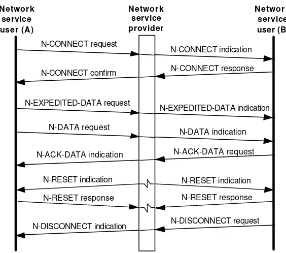
A sequence diagram defines a service protocol by specifying the permissible sequence of service primitives that may be exchanged between service users and service providers. Service users and service providers are represented by vertical bars. Service primitives are represented by directed lines between the bars. For clarity, primitive parameters are not included.
Figure 1.7 shows a simplified example of requesting a connection at the network layer. According to the diagram, a service user can request, from the service provider, a connection to a peer service user. The service provider in turn issues a connection indication to the peer service user. The peer service user responds to the service provider which, in turn, confirms the cycle with the original service user.
Figure 1.7 A simple sequence diagram.
Service
A state transition diagram describes the various execution states a station can assume and how service primitives cause it to transit from one state to another. States are represented by circles or boxes, and are labeled with a meaningful name that describes the state. A state transition is represented by a directed line from one state to another, and is labeled with the service primitive that triggers the transition.
Figure 1.8 shows an example which describes (in a simplified form) the states of a station at the network layer. According to the diagram, assuming that a station is in the idle state, if it issues a connection request to another station, it enters the
It is worth noting the complementary nature of sequence diagrams and state transition diagrams. The former specifies a service protocol from an outside observer’s point of view, while the latter describes the same protocol from a station’s point of view. The two notations, combined, provide a complete picture of how a protocol operates.
Figure 1.8 A simple state transition diagram.
N-CONNECT request
N-CONNECT
indication N-CONNECTresponse
N-CONNECT confirm attempting
to connect
awaiting
connectiona
idle connected
N-DISCONNECT
N-DISCONNECT N-DISCONNECT
1.5.
Standards
The importance of standards in the field of communication cannot be overstressed. Standards enable equipment from different vendors and with different operating characteristics to become components of the same network. Standards also enable different networks in different geographical locations (e.g., different countries and continents) to be interconnected. From a customer’s point of view, standards mean real cost savings: the same end-user device can be used for access to a variety of networks and services.
Standards are developed by national and international organizations established for this exact purpose. During the course of this book we will discuss a number of important standards developed by various organizations, including the following:
• The International Standards Organization (ISO) has already been mentioned. This is a voluntary organization with representations from national standards organizations of member countries (e.g., ANSI), major vendors, and end-users. ISO is active in many area of science and technology, including information technology. ISO standards are published as ISO serial-no (e.g., ISO 8632).
carriers, and the scientific community. CCITT standards are published as
Recommendation L.serial-no, where L is a letter of the alphabet (e.g., I.440). These are revised and republished every four years. CCITT standards are very influential in the field of telecommunications and are adhered to by most vendors and carriers.
• The Institute of Electrical and Electronic Engineers (IEEE) is a US standards organization with members throughout the world. IEEE is active in many electric and electronic-related areas. The IEEE standards for local area networks are widely adopted and will be discussed in Chapter 9. IEEE standards are published as IEEE serial-no (e.g., IEEE 908).
• The Electronic Industries Association (EIA) is a US trade association best known for its EIA-232 standard, which will be discussed in the next chapter.
• The European Computer Manufacturers Association (ECMA) is a standards organization involved in the area of computer engineering and related technologies. ECMA directly cooperates with ISO and CCITT.
In addition to these organizations, and because of their global market influence, large vendors occasionally succeed in establishing their products as de facto
standards. We will also look at a few standards of this nature later in the book.
1.6.
Further Reading
Communication is a vast subject area with many branches. Unfortunately the great majority of publications in this area are not at an introductory level. The most serious barriers a newcomer is faced with are layers of nomenclature and an inexhaustible supply of acronyms. One of the objectives of this book is to get the reader past these initial hurdles so that the publicly available literature becomes more accessible.
Overall, there are four good sources of reading to look into. These, roughly in increasing order of detail and complexity, are:
• Technical Magazines and Journals. There are many technical communications magazines and journals in circulation throughout the world, and new ones appear every year. The following are primarily US-based, but have a global readership, and are available in most university libraries:
• Bell Systems Technical Journal • Computer Communication Review • Computer Networks
• Data Communications • IBM Systems Journal
• IEEE Communications Magazine
• IEEE Computer
• IEEE Journal on selected Areas in Communication • IEEE Transactions on Communications
• Journal of Telecommunication Networks • Proceedings of the IEEE
• Telecommunications
• Product information. Also worth reading are publications by vendors on their network products. Product glossies, advertising literature, and user manuals are usually of introductory nature and easy to understand. Product handbooks, product specifications, and data books are typically at a much more technical level and therefore contain substantial detail. Unfortunately, it is not always easy to get hold of these publications, especially for larger products, such as telephone switches.
• Published standards. Communication standards are by no means easy reading material. These standards are often heavily cross-referenced and intended for very technically-minded readers. They are essential reading for those involved in the design and manufacturing of communication hardware and software, as they provide the necessary level of protocol specification detail required for these purposes. The CCITT standards as well as many others are available in most university libraries.
1.7.
Summary
• A computer network consists of nodes and communication links which implement its protocols. It interconnects a set of hosts which conform to the network protocols.
model. A point-to-point model may be based on circuit switching or packet switching.
• The OSI model proposes a seven-layer architecture for networks. Each layer is characterized by a set of protocols. The network nodes implement only the bottom three layers, while the hosts implement all the layers.
• The physical layer controls the transmission of raw data bits over communication lines. The data link layer facilitates the reliable transfer of data over communication channels. The network layer controls the end-to-end routing of data across the network. The transport layer manages the efficient and cost-effective transportation of data across the network. The session layer manages the negotiation of the establishment and termination of connections (sessions). The presentation layer provides a mutually-agreeable binary representation of application data (syntax). The application layer provides a mutually-agreeable meaning of application data (semantics).
• A service primitive is an abstract representation of the interaction between a service provider and a service user, and may be of one of four types: request, indication, response, and confirmation.
• A sequence diagram defines a service protocol by specifying the permissible sequence of service primitives that may be exchanged between service users and service providers.
• A state transition diagram describes the various execution states a station can assume and how service primitives cause it to transit from one state to another.
• Communication standards are essential in order to achieve interoperability between different equipment and networks.
1.8.
Exercises
1.1 Provide three arguments in favor of the use of a computer network in a modern organization, and at least one argument against.
1.2 Classify the networks operated and/or utilized by your organization as LAN, MAN, WAN, private, public, point-to-point, broadcast, circuit-switched, or packet-switched.
1.4 Explain the rationale behind the OSI seven-layer model. Briefly describe the role of each layer and its main functions.
1.5 What is a service primitive? Describe the main four types of primitives used for defining protocols.
1.6 Explain how sequence and state transition diagrams can be used to specify protocols. What aspect of a protocol is better captured by either diagram?
1.7 Draw a sequence diagram for the following: A service user sends a SEND request to a service provider which in turn sends a SEND indication to the peer service user. The latter sends a DATA request to the service provider which in turn send a DATA indication to the original service user. The peer service user then sends a SEND response to the service provider which in turn sends a SEND confirmation to the original service user.
1.8 Draw a state transition diagram for the following: A station is originally in the notsync
2.
The Physical Layer
This chapter examines the physical layer of the OSI model in detail. We will first look at a categorization of networking equipment, and then discuss transmission-related issues, including various transmission media. Multiplexing methods will be described next, followed by a discussion of two important physical layer standards: RS-232 and X.21.
After completing this chapter you should be able to:
• Distinguish between different network equipment types and understand their roles.
• Distinguish between different device connection types.
• Understand how data is transmitted and the basic techniques that this process involves.
• Have a broad understanding of the different physical transmission media and their characteristics.
• Understand the basic multiplexing methods and their role in data transmission.
2.1.
Equipment
This section briefly describes general networking equipment types and the types of connections that can be established between them.
2.1.1. Equipment Types
Network equipment may be classified into three broad categories:
1. Data Terminal Equipment (DTE) refers to user equipment that convert outgoing user data into a transmission signal, and convert back the incoming signal into user data. DTEs may take many different shapes and forms. Examples include: terminals, terminal adapters, personal computers, and mainframes. DTEs commonly reside at user sites.
2. Data Circuit-terminating Equipment (DCE) refers to the network equipment that connect DTEs to the network communication lines. In general, a DTE and a network line may use different types of signals (e.g., electrical versus optical). The necessary signal conversion between these two is performed by the DCE. A DCE may be a part of a DTE or be an entirely separate device. Modems and multiplexers are all examples of DCEs.
3. Data Switching Equipment (DSE) refers to network equipment used to connect DCEs together, thus providing switching capability to the network. DSEs correspond to the nodes in a network, and are responsible for routing data across the network. A DSE is commonly referred to as a switch. Digital telephone switches used in digital networks are examples.
Figure 2.9 illustrates the way DTEs, DCEs, and DSEs are connected in a network.
Figure 2.9 Network equipment types.
DSE
DTE
DTE
DCE DCE
DCE DCE
2.1.2. Connection Types
1. Simplex. This is a unidirectional connection, i.e., data can only travel in one direction. Simplex connections are useful in situations where a device only receives or only sends data (e.g., a printer).
2. Half-duplex. This is a bidirectional connection, with the restriction that data can travel in one direction at a time.
3. Full-duplex. This is a bidirectional connection in which data can travel in both directions at once. A full-duplex connection is equivalent to two simplex connections in opposite directions.
2.2.
Transmission
Transmission is the act of transporting information from one location to another via a signal. The signal may be analog or digital, and may travel in different media.
2.2.1. Signal Types
All signals are either analog or digital. An analog signal is one in which information appears as a continuous variation of some property. Human speech is an example: it produces a continuous variation of air pressure. A digital signal, on the other hand, is one in which information appears as a sequence of binary values 0 and 1. To represent these two values, a signal is used in which only two wave shapes are allowed, one representing the binary value 0 and the other representing the binary value 1. By definition, therefore, a digital signal is a restricted form of an analog signal. A human speaker who only utters the two words zero and one is a crude example of a digital signal.
In electrical terms, signals appear as variation of some electrical property (e.g., voltage). Figure 2.10 illustrates. In the analog signal example, the voltage freely varies between 0 and 5 Volts. In the digital signal, the voltage may assume only two values: 0 Volts to represent digital value 0 and 5 Volts to represent digital value 1.
Figure 2.10 Analog and digital signals.
5v
0v
5v
0v
time 1 0 1 1 time
analog digital
2.2.2. Modulation
Transmission of digital data over an analog line is achieved using a technique called modulation, where the digital bit stream is modulated over an analog carrier signal. A modem (modulator and demodulator) is a commonly used device which employs this technique. As illustrated in Figure 2.11, a modem converts the outgoing digital bit stream from a device into an analog signal and converts the incoming analog signal into a digital bit stream.
Figure 2.11 Role of modems.
modem modem
Three basic types of modulation are possible (see Figure 2.12 for a visual comparison):
1. Amplitude Modulation (AM). In AM, the carrier signal’s amplitude is changed according to the modulating digital signal’s bit value. For example, two amplitude sizes (a small and a large one) may be used to, respectively, represent bit values 0 and 1. AM’s main weakness is its susceptibility to distortion.
2. Frequency Modulation (FM). In FM, the carrier signal’s frequency is changed according to the modulating digital signal’s bit value. For example, two frequency values (a low and a high one) may be used to, respectively, represent bit values 0 and 1. FM is more resistant to distortion than AM.
Figure 2.12 Three basic modulation methods.
1 0 1 0
Modulating digital signal
Carrier signal
Amplitude Modulation (AM)
Frequency Modulation (FM)
Phase Modulation (PM) (bit stream 1010)
2.2.3. Digitization
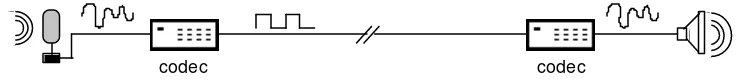
Digitization is essentially the opposite of modulation. Whereas in modulation a digital signal is modulated over an analog signal for transmission, in digitization an analog signal is converted into digital format through a process of sampling. For example, the analog signal resulting from human speech can be sampled and converted into digital data, transmitted over digital lines, and converted back to analog signal at the other end. These two functions are performed by a device called codec (coder/decoder). Figure 2.13 illustrates the concept.
Figure 2.13 Role of codecs.
codec codec
value which is in turn represented by an integer in the range 0-255 so that it can be represented in one byte of data. This process (of representing a continuous value with a discrete value) is called quantization. The relatively small loss of information inherent in the process is called quantization error.
The coding process generates the sample data from the analog signal. The decoding process regenerates an approximation of the original signal by fitting a smooth curve to the sampled points. The quality of the regenerated signal can be improved by increasing the sampling rate (i.e., reducing the sampling interval), but up to a limit dictated by the Nyquist’s theorem. This limit is exercised by a popular digitization technique called Pulse Code Modulation (PCM) which uses a sampling rate twice that of the original signal frequency. For example, a 4 kHz speech signal is sampled at a rate of 8000 samples per second.
The main advantage of digitization is that, due to its resistance to distortion, it is much easier to reliably transmit a digital signal over a long distance than an analog signal.
Figure 2.14 Sampling an analog signal.
0 127 255
5 10 15 20 miliseconds
2.2.4. Synchronization
When two devices are about to communicate, the transmitter should somehow notify the receiver as to when to expect to receive data. This allows the receiver to prepare itself for receiving the data. Furthermore, such notifications should occur frequently enough so that both devices maintain an agreement about the exact distribution of data over time. This process is called synchronization.
separate clock line increases the costs, it is only used for covering very short distances (e.g., for connecting personal computers).
Figure 2.15 Synchronous and asynchronous transmission methods.
clock
byte byte byte byte byte byte
sync byte sync byte
...
byte
stop bit start bit
byte byte byte ...
In asynchronous transmission, the beginning and end of each byte of data is marked by start and stop bits. This enables the receiver to work out the byte boundaries (see Figure 2.15). Because of its simplicity, asynchronous transmission is cheaper to implement and is therefore more widely used.
2.2.5. Transmission Media
Digital data can be transmitted over many different types of media. Selecting a transmission medium is guided by comparing transmission requirements against the medium’s characteristics. Four important criteria influence the choice:
1. Bandwidth. Bandwidth is the maximum frequency range that can be practically supported by a medium. This is usually expressed in kilo Hz (kHz) or mega Hz (MHz). For example, analog transmission of human speech typically requires a bandwidth of 4 kHz. Also related, is the notion of data rate, which denotes the maximum number of bits per second (bps) that can be transmitted. For example, a data rate of 10 mbps means that 10 million bits of data can be transmitted in each second. Because of their obvious relationship, the terms bandwidth and data rate are sometimes used interchangeably. Because of distortion factors, bandwidth and data rate are usually inversely proportional to the communication distance.
2. Cost. Two types of cost are relevant: (i) the cost of installing the medium, including the medium-specific equipment that may be needed, and (ii) the cost of running and maintaining the medium and its equipment. There is usually a need for tradeoff between cost, bandwidth, and distance.
4. Coverage. The physical characteristics of a medium dictate how long a signal can travel in it before it is distorted beyond recognition. To cover larger areas, repeaters are needed to restore the signal, and this increases the costs.
Transmission media may be classified into the following categories:
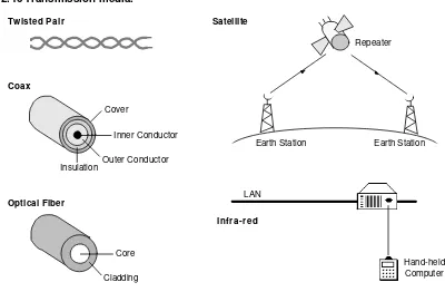
• Copper Wire. This is the oldest form of electronic transmission medium. Its use dates back to the development of telegraph in the 1800s and earliest telephone systems. Early installations used open wires, but these were superseded by twisted pairs, which consist of a pair of insulated and twisted wires (see Figure 2.16). Twisted pairs are superior because of reduced crosstalk.2 They are very
effective for relatively short distances (a few hundred feet), but can be used for up to a few kilometers. A twisted pair has a bandwidth to distance ratio of about 1 MHz per kilometer. The performance of the twisted pair can be substantially improved by adding a metallic shield around the wires. Shielded wires are much more resistant to thermal noise and crosstalk effects. Twisted pairs used for long distance connections (e.g., telephone lines) are usually organized as a much larger cable containing numerous twisted pairs.
• Coaxial Cable. A coaxial cable consists of four concentric cylinders: an inner conductor, surrounded by an insulating cylinder, surrounded by an outer conductor, surrounded by a final protective cover. This combination is called a coax (see Figure 2.16). Coaxial cables are superior to twisted pairs both in terms of bandwidth and communication distance, and can provide bandwidth to distance ratios in order of 10s of MHz per kilometer. Like twisted pairs, multiple coaxes are usually housed within one cable, which may also contain twisted pairs. Coaxial cables are extensively used in LANs and long distance telephone trunk lines.
• Optical Fiber. An optical fiber consists of two concentric cylinders: an inner core surrounded by a cladding. Both the core and the cladding are made of transparent plastic or glass material (see Figure 2.16). The core is used for guiding a light beam, whereas the cladding (which has a different refractive index) acts as a reflector to prevent the light from escaping from the core. Because optical fiber uses a light signal instead of electrons, it does not suffer from the various noise problems associated with electromagnetic signals. The signal is usually generated by a laser or Light Emitting Diode (LED). Optical fibers can provide bandwidth to distance ratios in order of 100s of MHz per kilometer. Like other cables, hundreds of optical fibers are usually housed within one cable. They are being increasingly used by telecommunication carriers for long distance
2 Crosstalk is the unwanted coupling effect between two or more signal paths, which causes signal
digital trunk lines. Current trends promise that they will replace twisted pair residential loops in the near future.
• Radio. Radio signals have been used for a long time to transmit analog information. They are particularly attractive for long distance communication over difficult terrain or across the oceans, where the cost of installing cables can be too prohibitive. A minimum radio system consists of a transmitter and a receiver. It may operate at a variety of frequency bands, ranging from hundreds of Hz to hundreds of giga Hz (GHz). A huge range of transmission bandwidths are therefore possible. Microwave is by far the most widely used form of radio transmission. It operates in the GHz range with data rates in order of 100s of mbps per channel. Telecommunication carriers and TV stations are the primary users of microwave transmission.
An important form of microwave system is a satellite system, which is essentially a microwave system plus a large repeater in the sky (see Figure 2.16). The signals transmitted by earth stations are received, amplified, and retransmitted to other earth stations by the satellite. Like other microwave systems, the bandwidth is subdivided into channels of 10s of MHz each, providing data rates in order of 100s of mbps. Because of their high bandwidths, satellites are capable of supporting an enormous number and variety of channels, including TV, telephone, and data. The satellite itself, however, represents a major investment and typically has a limited lifetime (at most a few decades).
Another increasingly-popular form of radio is cellular radio, which is currently being used by carriers for providing mobile telephone networks. These operate in the VHF band and subdivide their coverage area into conceptual cells, where each cell represents a limited area which is served by a low-power transmitter and receiver station. As the mobile user moves from one cell area to another, its communication is handed over from one station to another.
Figure 2.16 Transmission media.
Twisted Pair
Inner Conductor
Insulation Outer Conductor Cover
Coax
Core
Cladding Optical Fiber
Satellite
Earth Station
Repeater
Earth Station
LAN
Hand-held Computer Infra-red
Figure 2.17 compares the characteristics of these media using the criteria mentioned earlier. It is important to note that the figures provided are approximate and continually improve as the technology moves forward.
Figure 2.17 Relative comparison of transmission media.
Medium Bandwidth Data Rates Cost Reliability Coverage
Copper Cable 1 MHz 1-10 mbps Medium/km Low-Medium Kilometers
Coaxial Cable 10s of MHz 10-100 mbps High/km Medium-High 10s of Kilometers
Optical Fiber 100s of MHz 100s of mbps High/km Very High 10s of Kilometers
Radio 100s of MHz 100s of mbps Very High Very High 1000s of Kilometers
Infra-red 1 MHz 1-10 mbps Low Low-Medium Kilometer
2.3.
Multiplexing
2.3.1. Space Division Multiplexing(SDM)
SDM is the simplest (and crudest) form of multiplexing. It involves grouping many separate wires into a common cable enclosure. A cable that has, for example, 50 twisted pairs inside it can support 50 channels. There is therefore a one-to-one correspondence between physical and logical channels (see Figure 2.18).
SDM has the unique advantage of not requiring any multiplexing equipment. It is usually combined with other multiplexing techniques to better utilize the individual physical channels.
Figure 2.18 Space division multiplexing.
cable enclosure
2.3.2. Frequency Division Multiplexing (FDM)
In FDM, the frequency bandwidth of the line is divided into a number of partitions, each of which is used as a separate logical channel. Radio and TV broadcasting represent the oldest examples of FDM. To avoid neighboring channels from interfering with one another, the extreme ends of the channel frequencies are left unused to provide a gap. For example, a line that has a bandwidth of 30 kHz can be divided into 3 times 10 kHz channels, each of which consists of 8 kHz of bandwidth for data and two gaps of 1 kHz on either side.
FDM requires special multiplexing/demultiplexing hardware (MUX) at either end of the line (see Figure 2.19).
Figure 2.19 Frequency division multiplexing.
MUX MUX
8kHz
8kHz
30kHz
time 30kHz
20kHz 10kHz time
2.3.3. Time Division Multiplexing(TDM)
In TDM, each logical channel is allocated a time slot to transmit over a shared physical channel. For example, each logical channel may be given a 5 millisecond time slot to transmit, during which time it will have the entire bandwidth of the line to itself.
Like FDM, TDM requires special multiplexing/demultiplexing hardware (MUX) at either end of the line (see Figure 2.20). Because the channels are spread across time, some means of initial synchronization is also needed. Basically, the receiving end needs to know which time slot belongs to the first channel when the connection is established, and can work everything else out from this reference point.
Figure 2.20 Time division multiplexing.
MUX MUX
101
001
011
011 001 101 time slot
2.3.4. Concentration
In multiplexing, a predetermined bandwidth is reserved for each of the logical channels, the sum of which for all the logical channels equates the bandwidth of the line. In practice, none of the logical channels is fully utilized at all times by the equipment attached to them. Consequently, if the bandwidth of each of the channels could be dynamically adjusted according to its traffic, then some cost savings could be achieved by using a lower capacity line. For example, a 9600 bps line could be used to serve 10 times 2400 bps channels, assuming that no more than 4 channels are used at any one time.
Figure 2.21 Time slots in concentration.
001 10101 001 11111 010 01110 001 11011
Channel data
Channel address
Concentration is a popular method for connecting a set of character-based terminals to a central computer. Line capacity requirements are greatly reduced due to the fact that terminals tend to be idle for most of their operating period.
2.4.
Physical Layer Standards
The most commonly-used physical layer standards are those published by ISO, CCITT, IEEE, and EIA, many of which are inter-related. A large number of the existing standards deal with transmission over telephone lines. The CCITT V series of standards fall into this category and are by far the most-widely adopted.
Below we will look at two very popular standards for connecting DTEs and DCEs: the analog standard RS-232 and the digital standard X.21.
2.4.1. RS-232
RS-232 has dominated the computer industry as the most-widely used standard for physically connecting devices. It is an analog standard, defining the physical layer interface between a DTE and a DCE, and can support simplex, half-duplex, and full-duplex connections in synchronous as well as asynchronous mode. It originated in the late 1950s, and has been revised a number of times over the years. The latest revision, EIA-232-D, is based on CCITT’s V.24 and V.28 standards and ISO’s 2110 standard.
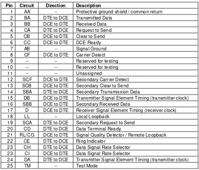
ISO 2110 defines the mechanical appearance of the RS-232 connectors (see Figure 2.22). The connector provides 25 pins for connecting the circuits derived from the V.24 standard, as summarized in Figure 2.23. The circuits are used for data transfer, conveying of control signals, and conveying of clocking signals for synchronization.
Figure 2.22 RS-232 connector (based on ISO 2110).
1 2 3 4 5 6 7 8 9 10 11 12 13
14 15 16 17 18 19 20 21 22 23 24 25
Figure 2.23 V.24 circuits.
Pin Circuit Direction Description
1 AA -- Protective ground shield / common return 2 BA DTE to DCE Transmitted Data
3 BB DCE to DTE Received Data 4 CA DTE to DCE Request to Send 5 CB DCE to DTE Clear to Send 6 CC DCE to DTE DCE Ready
7 AB -- Signal Ground
8 CF DCE to DTE Carrier Detect
9 -- -- Reserved for testing
10 -- -- Reserved for testing
11 -- -- Unassigned
12 SCF DCE to DTE Secondary Carrier Detect 13 SCB DCE to DTE Secondary Clear to Send 14 SBA DTE to DCE Secondary Transmission Data
15 DB DCE to DTE Transmitter Signal Element Timing (transmitter clock) 16 SBB DCE to DTE Secondary Received Data
17 D DCE to DTE Receiver Signal Element Timing (receiver clock)
18 LL -- Local Loopback
19 SCA DTE to DCE Secondary Request to Send 20 CD DTE to DCE Data Terminal Ready
21 RL/CG DCE to DTE Signal Quality Detector / Remote Loopback 22 CE DTE to DCE Ring Indicator
23 CH DTE to DCE Data Signal Rate Selector 23 CI DCE to DTE Data Signal Rate Selector
24 DA DTE to DCE Transmitter Signal Element Timing (transmitter clock)
25 TM -- Test Mode
Figure 2.24 Typical half-duplex connection using RS-232.
RS-232 has two important limitations which reduce its usefulness: it is not suitable for distances of more than about 50 meters, and it has a maximum bandwidth of 20 kbps. Other similar standards have been devised to overcome these limitations. For example, RS-449 and EIA-530 can both support data rates of up to 2 mbps over longer distances.
2.4.2. CCITT X.21
X.21 is a widely-accepted standard for interfacing a DTE to a DCE of a digital network. It can be used for connections of up to 1 km in length and data rates of up to 10 mbps (for distances less than 10 m). X.21 uses a connector based on the ISO 4903 standard (see Figure 2.25).
The connector provides 15 pins for connecting the circuits derived from the X.24 standard, as summarized in Figure 2.26. Unlike RS-232, the same transmit and receive circuits (T and R) are used for the exchange of control as well as data signals.
Figure 2.25 X.21 connector (based on ISO 4903). 1 2 3 4 5 6 7 8
9 10 11 12 13 14 15
Figure 2.26 X.24 circuits.
Circuit Direction Description
G -- Protective ground shield / Common Return Ga DTE to DCE DTE Common Return
Gb DCE to DTE DCE Common Return T DTE to DCE Transmit
R DCE to DTE Receive C DTE to DCE Control
I DCE to DTE Indication
S DCE to DTE Signal Element Timing B DCE to DTE Byte Timing
F DCE to DTE Frame Start Identification X DTE to DCE DTE Signal Element Timing
Figure 2.27 Typical full-duplex connection using X.21.
DTE DCE
Byte Timing Ground
DTE Common Return
Signal Element Timing Indication
Receive Control Transmit
X.21
X.21 bis is a variation of the X.21 standard with similarities to RS-232: it uses the V.24 circuits and is usually used with the 25-pin connector of ISO 2110.
2.5.
Further Reading
Black (1988), Blahut (1990), Bic et al (1991), and Gitlin et al (1992) provide detailed descriptions of physical layer topics such as interfaces, coding, modulation, transmission, synchronization, error-handling, and standards. McClimans (1992) describes different transmission media and their properties. Stone (1982) describes detailed examples of (mainly RS-232) physical layer interfaces for microcomputers.
2.6.
Summary
• Network equipment are classified into DTE (user equipment), DCE (connect DTE to network), and DSE (perform switching between DCEs).
• A signal may be analog (continuous variation of some property) or digital (sequence of binary values 0 and 1).
• Digital data is transmitted over analog lines using modulation and converted back to digital format using demodulation. These two functions are performed by a modem. Modulation method are classified into AM, FM, and PM.
• Converting an analog signal into digital is called digitization and is performed by a codec. PCM is a popular digitization method for voice signals.
• Transmission methods are classified into synchronous (clock-based) and asynchronous.
• Popular transmission media include: copper wire, coaxial cable, optical fiber, radio, and infra-red.
• Multiplexing methods are divided into SDM (multiple wires in a common enclosure), FDM (subdivision of the frequency bandwidth into logical channels), and TDM (allocation of time slots to each logical channel).
• Concentration is a variation of TDM where time slots are allocated on demand.
• RS-232 is a popular analog standard for the physical interface between a DTE and a DCE.
• X.21 is a popular digital standard for the physical interface between a DTE and a DCE.
2.7.
Exercises
2.9 Describe the role and functions of DTEs, DCEs, DSEs, and name an example of each device type.
2.10 State the differences between an analog signal and a digital signal. Provide an example of either signal type.
2.11 Describe the differences between modulation and digitization. Name the devices that perform these functions.
2.13 Consider the problem of providing a 2 mbps physical connection between two LAN sites which are 10 kms apart and are located in the same city. Discuss the merits of using different types of transmission media for this purpose.
2.14 What is the purpose of multiplexing? Compare the strengths and weaknesses of FDM and TDM.
2.15 Describe how a 100 MHz line with a data rate of 200 mbps can be divided into 20 channels using FDM and TDM.
3.
The Data Link Layer
This chapter looks at the data link layer of the OSI model. The data link layer transforms the logical communication channel provided by the physical layer into a reliable channel by splitting the data into frames which are subjected to error control and flow control procedures.
We will first look at various link protocol types, and then describe the constituent functions of link protocols, such as acknowledgment of frames, error checking, and flow control. These functions are embodied by a general technique called the sliding window protocol, which will be described next. Finally, we will discuss two popular data link standards: BSC and HDLC.
After completing this chapter you should be able to:
• Distinguish between different data link protocol types and know the characteristics of each type.
• Have a general understanding of the various data link protocol functions.
• Explain how the CRC error checking method works and how a CRC code is calculated.
• Understand the sliding window protocol and explain how it can be used for flow control.
• Describe the BSC character-oriented data link protocol, including its block format and functions.
3.1
Link Protocol Types
Data link protocols are divided into two basic categories: synchronous and asynchronous. These are described below.
It is important not to confuse synchronization at the data link layer with synchronization at the physical layer. These two are distinct and essential in their own right: physical layer synchronization ensures that the transmitter and the receiver share a common clock signal so that bit boundaries can be detected; data link layer synchronization ensures that user data is not confused with control data.
3.1.1. Synchronous Protocols
Synchronous protocols operate by delimiting user data with unique bit patterns which the receiver uses to detect where the user data begins and where it ends. Synchronous protocols may be character-oriented or bit-oriented.
In a character-oriented protocol, user data consists of a sequence of characters and is delimited by two unique control characters (SYN and EOT). The biggest disadvantage of character-oriented protocols is that they are based on specific character sets (e.g., ASCII or EBSDIC) and are therefore character-set dependent.
In a bit-oriented protocol, no specific character set is assumed. The unit of transmission is a frame, which consists of user data (an arbitrary bit sequence), control data, address data, error checksum, and two delimiting bit patterns at either end of the frame. Figure 3.28 illustrates the frame structure for HDLC protocols (discussed later in this chapter).
Figure 3.28 HDLC frame structure.
Field Description
01111110 Start flag: marks the beginning of the frame. Address Address of the host for which the frame is intended.
Control Record frame type, frame sequence, flow control, etc.
Data Contains the actual user data and is a bit sequence of arbitrary length.
Checksum A checksum field for error detection. 01111110 End flag: marks the end of the frame.
consecutive 1 bits it finds. This is called bit stuffing; its effect is canceled by the receiver, which removes every 0 bit that occurs after every five consecutive 1 bits.
Bit-oriented protocols are by comparison more recent than other protocols and have dominated the market. To acknowledge their importance, most of this chapter is devoted to the description of this class of protocols.
3.1.2. Asynchronous Protocols
Asynchronous protocols are character-oriented and operate by having the transmitter surround each character with a start and a stop bit. These two bits indicate to the receiver where the character starts and where it ends. The receiver extracts the user data by removing the start and stop bits.
3.1.3. Master-Slave Protocols
Master-slave protocols are used in situations where a primary station (such as a host) controls one or more secondary stations (such as peripheral devices). Communication between the master and its slaves is governed by a general technique called polling. Polling is typically used in a multidrop line configuration where, for example, a set of terminals are connected to a host via a shared communication line.
In its simplest form, polling works as follows. The master can send data in form of a message to any of the slaves. The message contains an address which uniquely identifies the slave for which it is intended. To receive data from the slaves, the master ‘polls’ each slave in turn by sending a message to it and asking if it has any data to send. The slave responds by either sending data or by sending a rejection message to indicate it has nothing to send.
3.1.4. Peer-to-Peer Protocols
In peer-to-peer protocols, all stations have similar status and communicate in a democratic fashion. The majority of network link protocols fall into this category. The carrier-sense protocol serves as an example, where all stations share a common communication channel. To transmit, a station monitors the channel for transmission by other stations and awaits its becoming free. Once the channel is free, the station starts transmitting. Collisions (when two stations attempt to transmit simultaneously) are resolved by requiring a transmitting station to monitor the channel at the same time and stop the transmission if it detects another station also transmitting. The collided stations then wait for some random period of time before attempting to retransmit.