Increase of In
-
Situ Measured Shear Wave Velocity in Sands with
Displacement Pile and Stone Column Inclusions
Franciscus Xaverius Toha
Geotechnical Research Group, Faculty of Civil and Environmental Engineering, Institut Teknologi Bandung
CIBE Building, Room 05-11, Jl. Ganesha No. 10 Bandung 40132
E-mail: [email protected]
Jurnal Teoretis dan Terapan Bidang Rekayasa Sipil Jurnal Teoretis dan Terapan Bidang Rekayasa Sipil
Abstract
Seismic downhole and MASW measurements were conducted at a potentially liquefiable site, where PC piles and stone column inclusion were provided to remediate the foundation soil. The selected site is part of a refinery located in high seismicity zone. The seismic measurements were done prior and after the PC piles and stone columns were installed. The densification, reinforcing, and dissipation contribution to the overall mitigation was elaborated herein. The measurement results are essentially consistent with the most recent theoretical developments and indicate that the strengthening due to mitigation is higher than predicted.
Keywords: Cyclic shear stress distribution,lateral pile capacity, seismic pore pressure, seismic shear wave velocity, stone columns.
Abstrak
Pada situs yang berpotensi likuifaksi dengan sisipan tiang pancang PC dan tiang batu, dilakukan pengukuran seismik turun lubang dan MASW. Lokasi yang dipilih adalah bagian dari sebuah kilang minyak yang terletak dalam zona gempa tinggi. Pengukuran seismik dilakukan sebelum dan sesudah pemancangan tiang PC dan tiang batu. Uraian mendalam tentang sumbangan pemadatan, perkuatan dan disipasi terhadap keseluruhah mitigasi disampaikan di sini. Hasil pengukuran pada dasarnya konsisten dengan perkembangan teoritis terkini dan menunjukkan bahwa perkuatan akibat mitigasi masih di atas perkiraan.
Kata-kata Kunci: Distribusi tegangan geser siklik, kapasitas lateral tiang, kecepatan gelombang geser seismic, tegangan pori seismic, tiang batu.
1. Introduction
In high seismicity areas where loose saturated sands are present near to ground surface, liquefaction may impose serious damage to foundation structures. The pore water pressure increase will result in loss of foundation capacity and damage due to large deformations. Mitigation efforts to ensure satisfactory performance of the foundation soil and structure, basically comprise of methods to prevent development of high pore pressures in the sand layer (Mitchell, 2008). These efforts may consist of increasing the density of the sand , provision of drainage in the sand layer during the earthquake, and reinforcing the sand layer by inclusion of stiffer geo or structural elements. Among others, are densification (Dise, et al., 1994; Tsukamoto, et al., 2000), stone columns (Boulanger, et al., 1998), deep mixing (Matsuo, et al., 1996; O’Rourke, et al., 1997; Porbaha, et al., 1999), grouting techniques (Martin et al., 2007), prefabricated seismic drains (Rollins, et al., 2004), desaturation of pore water (Yegian, et al., 2007), and many more. This study presents a remediation by inclusion of Prestressed Concrete (PC) piles and stone columns in sand layers, both installed by large displacement method, such that the densifying, reinforcing and dissipation effects are present.
This paper presents a case where liquefaction mitigation for a piled foundation area supporting structures of residue fluid catalyc cracking plant at a refinery site in Cilacap,
Indonesia, was done by adding stone columns in the piled area. A portion of the plant, which is the main process area of the new refinery, as shown in Figure 1, is situated at approximately at 7o 41’ 54.84” S altitude
and 108o 59’ 39.71” E latitude on the Donan River
bank, in close proximity of the Eurasian and Australian tectonic plate collision. The site was part of an existing refinery, which seems to be reclaimed during the previous development stage. Some part of the site was used for waste material dumping during the previous construction, and some of the waste material had to be re excavated to enable piling works. The re excavation may impose loosening of the in situ soil, as there were several deep excavations where back filling could not be done with intensive compaction. Most of the structures at this site are supported by PC pile foundations, intalled by driving. The pile foundations of the structures were designed against the seismic loads according to the then prevailing Indonesian Seismic Code, SNI 03-1726-2002.
was mostly based on the existing data. Additional investigations were done mainly for verification purposes, including the verification of the liquefaction mitigation design. Although the mitigation design was based on the best available knowledge at the time, new developments emerged, consequently additional insights related to the developments are elaborated in this paper. The verification of the design, was done, among other methods, using seismic downhole and Multichannel Analysis of Surface Waves (MASW) tests. The verification results were used in this paper to present more in depth views on the improvement mechanism.
2. Pre
-
Construction Soil Properties
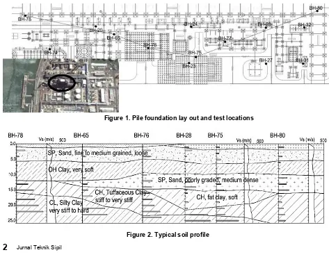
Part of the results from an extensive soil investigation program are summarized herein. At the site of the main process area, as shown in Figure 1, fourteen of the boreholes were shown for the elaboration, and some of which are with seismic downhole tests. Figure 2 shows a profile of the soil layers along a line shown in Figure 1. From the site and laboratory test results it was established that the upper 5 to 6 m surface layer is a fine silty sand (SM) from previous reclamation having NSPT
values between 2 to 12 blows/ft., with an estimated relative density, Dr, of 20 to 50%. The sand has a D50 of 0.1 to 0.12 mm, and a clay content of 10 to 15 %. The upper sand layer is followed by a very soft organic clay (OH) with NSPT as low as 1 to 3 blows/ft., with an estimated undrained shear strength of 5 to 15 kPa. At some spots, the OH clay layer appears on the surface,
and at some other locations, the thickness is more and the clay is displaying lower shear strength. Most of the pile to pile cap or slab joints under the structure will be within these two weak layers. Seismic downhole tests were carried out to obtain the shear wave velocity, vs, profile in the layers. Prior to the construction works, the average vs in the SM sand layer was 130 to 170 m/ sec., and in the OH clay, the measured vs was 110 to 150 m/sec.
3. Pile Foundation and Stone Column
Configuration
Prestressed Concrete (PC) piles are used for the foundations of the structure of the plant. The pile ODs are 500 mm and 600 mm, with average lengths of 30 m below the pile caps. For the 500 mm and 600 mm PC piles, the respective maximum crack moments,
Mcrack, are 150 kN-m and 250 kN-m; while the
respective allowable lateral loads, Hall, are 78 kN and 107 kN. Stone columns with a 1000 mm diameter were provided to increase the PC piles capacity during the earthquake. The stone column lengths are 10 meters below the pile caps and base slab, with 20 mm – 50 mm crushed rock as aggregate material. The spacing of the stone columns was set to be maximum 3.5 meters from the protected piles. Figure 3 presents the typical lay out and cross section of the pile and stone column system. At the top of the stone columns, a gravel bed was provided to dissipate the pore pressures through the relief wells.
Figure 1. Pile foundation lay out and test locations
To prevent PC pile damage, the stone columns were installed prior to the PC piles, as a large displacement method of installation was adopted to obtain as much as possible densification in the soil during penetration. Steel casings with diameters of 1000 mm were driven with a closed end. When the design depth was reached, the casings were extracted while adding crushed rock aggregate in its annulus, by means of a 90 to 120 kW vibro hammer. During extraction, the casing bottom plate would open and allow crushed rock insertion into the ground. The duration and frequency of vibration was adjusted to obtain a certain stone column diameter and densification in the surrounding sand. Following the stone column installation and after soil preloading with prefabricated vertical drains, the PC piles were installed, also using large displacement methods. Due to schedule restrictions, there were no SPT or CPT verifications on the sand density and the OH clay shear strength after the PC pile installations. Downhole seismic and MASW test were done a few months after piling.
In this paper, the piling and stone column configurations in the main process area of the refinery site, in relation to the expected improvement results, are quite variable. For pile groups with fewer PC piles, the densification effect of stone column inclusion is not expected to be significant. In large PC pile groups, where there are a large number of piles, and the pile spacing is reasonably tight, the densification effect of the pile and stone column installation is expected to be significant. In this paper, there are three basic configurations used in the elaboration of the
RX
-Figure 3. PC pile and stone column configuration
analysis. The first configuration is the large pile cap on the RX-RG tower, where the PC piles and stone
columns occupy about 33% of the total area where the sand is included. Secondly, for pile caps of concentrated columns of pipe rack structures, such as those near BH-78 and BH-80, the ratio is about 16% to 18%. For
consideration along the MASW seismic survey lines, the ratio is 6% to 7%.
4. Seismic Parameters at the Site
A site specific seismic study was conducted for the site (Sengara, 2012) during the design and built process of the plant structures. The seismic design of the piles followed the prevailing Indonesian seismic code according to the contract, i.e. SNI 03-1726-2002. The
particulars are as shown in Table 1.
Acceleration and displacement spectra were established, both for cases with or without liquefaction occurrence, based on NSPT of 2 to 12 blows/ft., and according to Seed and Harder (1990) which gave an estimated undrained
Table 1. Seismic parameters
Seismic Parameters Value
Earthquake Return Period 475 years Peak Base Acceleration, PBA 0.275 g Deaggregated Magnitude, Mw 8.03
Source Distance, R 92.5 km
RX-RG
shear strength of liquefied sand of about 3 kPa, using at least 7 deaggregated input motions. In addition, the study also included an assessment of spectra where the generated pore pressures were accounted for, by reducing theequivalent shear wave velocity of the sand layer to ratios of 0.9, 0.8, 0.7, 0.6 and 0.5 of the pre-construction shear wave velocity.
5. Mechanism of Liquefaction Remediation
by Stone Columns and Other Inclusions
Although the use of stone columns to mitigate liquefaction hazards has been around for almost half a century, the general consensus about its effectiveness in practice has been under continuing criticisms. Some clear cut conditions, such as when the sand is coarse and with low fine content, the benefit from merely densifying the sand may be sufficient to eliminate the need for stone columns or other type of inclusions. In this case, the increase in the density of the sand is sufficient to prevent liquefaction. On the other extreme, when the sand is fine and contains appreciable amount of silt, hence difficult to densify, inclusions such as stone columns, cement mixed columns, or piles are more relied upon for its reinforcing and pore pressure dissipation effects. The early stone column use for liquefaction mitigation was based on very simple assumptions. Early on, the stone columns were designed by assuming that the stone column acts as a system to dissipate the pore pressures quickly; and also assuming the stone column as a reinforcement to the sand layer, such that the cyclic shear stress in the sand is reduced. This approach has received on going disputes, mostly arguing about the limiting criteria for each improvement mechanism. Nevertheless, the use of stone columns has proven to demonstrate positive performance during large earthquakes. Earlier publications on stone column performance include Mitchell and Huber (1985), Dobson (1987), Mitchel and Wentz (1991); and Hayden and Baez (1994). More recent cases are reported by Hausler and Koelling (2004), Young et al. (2012); as well as Mahoney and Kupec (2014).
This paper presents a case where all the three features of liquefaction remediation using stone column and PC pile inclusions were used. The combined effects of the inclusions will increase the pile foundation lateral load capacity and stiffness, albeit the structural moment
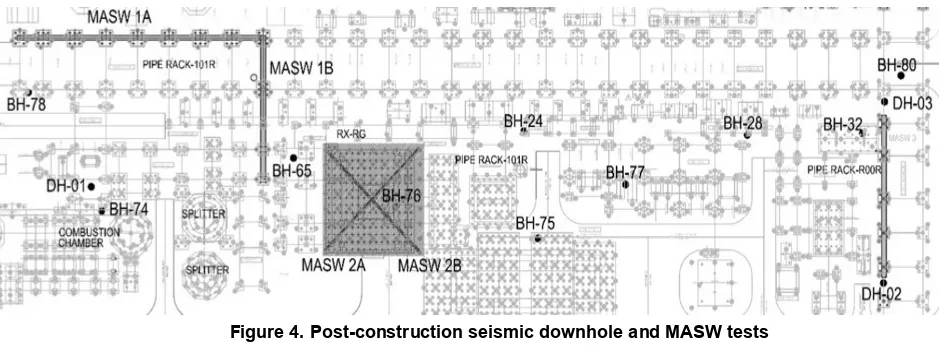
capacity of the PC piles remains constant. As part of the performance criteria, post construction seismic downhole as well as MASW measurements were done. The locations of the post construction tests are shown in Figure 4, together with some of the preconstruction borehole locations.
The early methods of verifying the improvementefforts consist of SPT or CPT measurements to quantify the increase in density after improvement. This method is sufficient if the increase in density ensures liquefaction elimination in the sand layer. For this plant site, unless the PC pile and stone column configuration is very dense, it was believed that the densification alone would not be sufficient. The more recent analytical studies show that the integral performance of the sand, as well as the inclusions, will dictate the ground response, both in terms of acceleration and deformation. This was the reason for selecting seismic measurements at the site. Complementary to the seismic tests in this study, there are a few recent publications on the similar approach. Wissman et al. (2015) reported test results on sandy and silty soils, where cross hole seismic tests and vibroseismic tests were performed on stone columns. In both, the cross hole and the vibroseismic tests, the parameters were measured in the sand in across or in between stone columns. The tested area was of limited extend. An MASW method was used by Stuedlein et al. (2015), also for a stone column invested area. In this later study, lower shear wave velocity was detected after the improvement works. It was argued that this observation was attributed to the predrilling prior to the stone column installation and the short of time between installation and measurement. In this study, the cross hole and MASW tests were done sufficiently long after installation; in areas where two distinctly different inclusions, i.e. PC piles and stone columns, were present; and over extended areas with varying inclusion densities.
5.1 Densification remediation
The use of a large number of PC piles and stone columns in heavily loaded areas imposed reasonably large displacement during installation. The pre
-construction NSPT in the SM sand layers varied between 2
to 12 blows/ft., which gives an estimated relative density,
Dr, of 30 to 50%. Since D50= 0.1 to 0.12 mm, and the fine content of this sand was 10 - 15%, this sand is
borderline unsuitable for deep vibro compaction. The densification by forced displacement from the inclusion of PC piles and 1000 mm stone columns will be more significant.
The MASW vs measurements shown in Figure 4, were done in three groups. MASW 1a and 1b are located in the pipe rack area, where the structure is supported by columns with a few PC piles and stone columns, at relatively large column spacing. Likewise, MASW 3 was also done for large column spacing area, but the soil conditions are better at this site. MASW 2a and 2b were done in an area densely populated by PC piles and stone columns. The seismic downhole tests, DH-01, DH-02 and DH-03, were done in within blocks
with a few PC piles and stone columns, but the density within the stone column effective area of influence is still high. Downhole seismic tests were done at BH24, BH 32, BH75, BH78, BH 75, and BH80 during the soil investigation stage, before the inclusions of stone columns and PC piles.
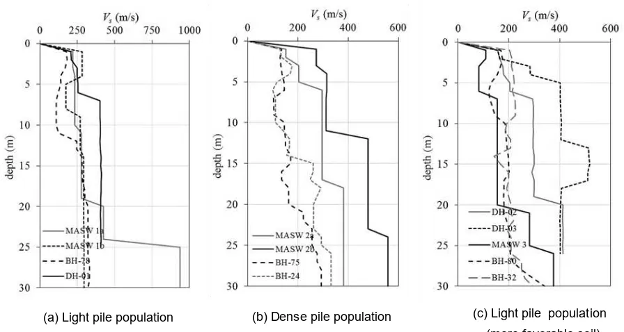
Results of vsmeasurements prior and after the PC pile and stone column installation are summarized in
Figure 5. The results show a definite increase in the vs
values after the PC piles and stone columns were introduced. For the upper 10 m layers, the increase varies from 50% to more than 100%. Most of the MASW results at larger depths indicated a more pronounced increase. MASW 3 is considered the same as the downhole test from and BH 32 and BH-80. The
comparably high pre-construction vs value from
BH-78, is attributed to the fact that the deeper stiff clay
at BH-78 has NSPT values of more than 40 blows/ft.,
significantly higher than the pre-construction boreholes at
the MASW 1a, 1b and DH-01 sites. Likewise, for the
upper layers, MASW results give higher vs values compared to downhole tests, due to drilling disturbance near the surface before the downhole tests. The adverse results observed by Stuedlien et al. (2015) was not present at this site, as the MASW tests were done at reasonable time after PC pile and stone column installation, and there was no predrilling involved.
As DH-01, DH-02 and DH-03 were done at centers of
PC piles and stone columns, it is not surprising that the measured vs values are higher than that of the MASW 1a, MASW 1b, and MASW 3 tests, where the later covers a larger area, hence, the overall density of the PC piles and stone columns is less. For MASW 1b and MASW 3, only a slight increase in vs at depths of 5 to 10 m occurred in the soft OH clay layer. Since the OH layer on the MASW 1b site is in a spot near BH-65 and
BH-76, where the OH clay has a much lower shear
strength than at BH-75, it requires more time to
consolidate and gain effective stress increase after inclusion of PC piles and stone columns.
In general, the observed increase in vs is about 50% to more than 100%. This increase can be associated with a 20% to 40% increase in shear modulus, G. Using Hardin (1978) and Jamiolkowski et al. (1991), it was deduced that if all the gain in vs was attributed to densification, then the accompanying radial strain should be about 10 to 20%. In order to illustrate the improvement parameter, the ratio of the area replaced by the PC piles and the stone columns, to the total area of treated sand, Ar, is used to evaluate the improvement effects. In MASW 1a, MASW 1b, and MASW 3 sites, Ar is about 16% to 18%, near the downhole test area, and about 7% if averaged along the MASW lines. In MASW 2a and 2b area, Aris as high as 33%.
(a) Light pile population (b) Dense pile population (c) Light pile population (more favorable soil)
According to Chong (2013), as well as Massarsch and Wersall (2013), the lateral displacement due to pile driving is in the order of 10 % to 30% of the pile radius. For the Ar values on the MASW 1a, 1b and 3 sites, this gives a radial strain of only 1 % to 4%. Therefore, it can be concluded that the gain in vs is not solely induced by the densification in this sparsely treated area. On the other hand, for areas with a lot of PC piles and stone columns, with Ar = 33%, it is possible that the inclusion will result in a recorded increase in vs that is caused solely by densification. At greater depths, where most tests result after installation are significantly higher than pre-construction results,
the contribution of densification to the observed increase in vs is less likely.
5.2 Reinforcement by PC pile and stone columns
The inclusion of PC piles and stone columns is intended to reduce the cyclic shear stress in the sand layer. Since early on, this concept of shear strain compatibility was used by, among others, Priebe (1991), Baez (1995), Adalier and Elgamal (2004), Mitchell (2008), Durgunoglu (2006), for stone columns analysis. In this concept, the distribution of seismic shear stresses is shared by the inclusions and the sand proportional to the shear stiffness, represented by the product of area and shear modulus. This concept implies shear strain compatibility between the sand and inclusion. With a large number of PC piles and several stone column inclusions, a significant portion of the seismic shear stress would be carried by the PC piles and stone columns according to this concept, hence the remaining shear stress in the sand will be much less such that the liquefaction potential is greatly reduced. Since Goughnour and Pestana (1998) disputed the strain compatibility concept, by arguing that the stiffer inclusions also deform in flexure, consequently, the reduction of cyclic shear stress in the sand, will not be as large. Most recent numerical method verifications (Rayamajhi, et al., 2014; and Rayamajhi, et al., 2016) as well as dynamic centrifugal testing results (Rayamajhi, et al., 2015) supported Goughnour and Pestana (1998) arguments. Based on comparing the ground response of the improved and unimproved soil, the ratio of seismic strain in the inclusion to the strain in the sand (= gpc/sc/gs), and CG is a shear factor (= 1.0 for circular inclusions, and ~ 0.5 for rectangular grids). An expression based on parametric finite element study by Rayamajhi et al. compatibility can only be achieved at gr = 1.0, which yields Gr = 1 as well, which is valid only if there is no
below the below the pipe rack columns, and along the
MASW lines; where the Arvalues are 33%, 16%-18%
and 6%-7%, respectively; the small strain Gs = 57
MPa, Gpc = 14,600 MPa, and Gsc = 1,400 MPa; the Rrd
values in the sands are 63%, 77% and 89%; respectively. Furthermore, from Equation 3, evaluating vs after remediation from the obtained average shear modulus,
Gavg, the vs values increase by 67%, 30%, and 11% for Ar
values of 33%, 16% - 18% and 6% - 7%, respectively. It
should be noted, that the said figures were assessed by neglecting the densification effect, and the composite Ar
of the PC piles and stone columns was obtained using elastic shear approach. The results show that the increase in the measured vs are somewhat higher compared to the predictions if the densification effect is ignored, which means that the improved results are caused by both the densification as well as due to the reinforcement effects of the stiffer inclusions. If the effect of densification is included, the results at greater depth show that the measured vs is still higher than predicted, since the densification at greater depth would be small.
The predicted reduction of cyclic shear stress in the sand is not as negligible as argued, especially in the densely populated PC piles and stone columns sites. Since the measured vs in the MASW as well as downhole test are higher than the values otherwise predicted through Equation 3, more favorable seismic response of the area with PC piles, stone columns and densified sand will occur, where the resulting cyclic shear strains will be less, and therefore the liquefaction potential is reduced.
5.3 Pore pressure dissipation
The generated pore pressures in the SM sand layer must be dissipated quickly by the stone columns, gravel bed and vertical relief wells at this site. An elaborated analysis of the dissipation capacity of the stone column, gravel bed and relief system was reported by Toha pressure dissipation within the sand layer is governed by radial rate of consolidation equation. A method according
to Seed and Booker (1977) was used here. The pore pressure generation and dissipation in the silty sand (SM) was evaluated based on the seismic parameters in Table 1, and considering both the densification and reinforcing effect due to the PC piles and stone columns, the maximum excess pore pressure in the sand was estimated to be about 20% of the initial total stress. This generated pore pressure will result in a reduced vs of 70% of the initial value.
6. Response Spectra
As described earlier, the installation of PC piles and stone columns using displacement methods increased the measured vs. Using the vs from measurements after the PC piles and stone columns were installed, and applying the design earthquake to assess the generated pore pressures, and subsequently dissipating the pore pressures through the stone columns and its downstream gravel bed and relief well system, the residual pore pressure will reduce the vs in the sand to 70% of the value at the time before construction started. The reference to pre-construction vs values was due to the intent to utilize
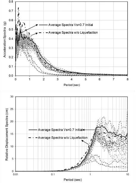
the site specific response spectra analysis (Sengara, 2012) results. where results for several residual vs values, ranging from 100 % (no residual pore pressure) down to 50 % of its pre construction vs were readily available. Figure 6 exhibits the acceleration and relative displacement response spectra where the residual vs in the sand is 70% of the pre-construction
value.
Figure 6. Acceleration and relative displacement spectra
The acceleration spectra show that the spectral values are less compared to the case where no excess pore pressure developed, especially at periods below 1 second. On the other hand, the displacement spectral values are higher at periods above 1 second. This is in line with the general consensus that liquefaction tend to reduce the seismic forces, but will increase the displacements, often into unacceptable values. As all the structures at this plant has a natural period of less than 0.5 second, the displacements from the spectra are still within acceptable limits. The performance of the PC piles during the design earthquakes were not evaluated in the scope of this study, as it required separate analysis for each building.
In the derivation of Equation 1, Rayamajhi et al. (2014) observed from the numerical study, that the spectral accelerations at the ground surface of the sand with discrete inclusions are almost the same as the untreated case, and the formulations are based among others, on this assumption. This is certainly not true if the effect of generated pore pressure is included and Gs
as well as vs are reduced as a result. The maximum acceleration, and thus the cyclic shear stress in the sand, will also be reduced. As the shear modulus in the sand will be reduced due to pore pressure increase, the reduced shear stress, may or may not increase the shear strain. In centrifugal tests, Rayamajhi et al. (2015) observed that there was a slight delay in the initiation of liquefaction, when stiff column inclusion was provided. In addition to the results of the response spectra analysis and the post construction vs measurements, as well as considering the results of vibroseis test as reported by Wissmann (2015), the contribution of the reinforcement mechanism in the recently proposed methods is likely somewhat underestimated.
7. Conclusions
The conclusions from a study on series of field shear wave velocity measurements sand layers of a high seismicity site, are as follows:
1. The seismic downhole and MASW test results are reasonably consistent with the predictions using more recent method of analysis using the data from soil investigations and seismic downhole tests before construction.
2. The measured shear wave velocity after the installation of PC piles and stone columns using displacement methods are appreciably higher than prior to the construction. Judging from the results, it is unlikely that densification or reinforcement alone is contributing to the observed gain after PC piles
and stone columns installation. Both the densification and the reinforcement by the PC
piles and stone columns caters a higher overall shear wave velocity, and therefore the seismic shear strains will be smaller.
gain in shear wave velocity is predominantly caused by either densification or reinforcement effects. The theoretical predictions were consistent with the field shear wave velocity measurement results, as in areas where the PC piles and stone columns cross sectional area is relatively low compared to the total area, the increase in the shear wave velocity is small.
4. The predicted reduction of cyclic shear stress in the sand is not as negligible as argued, especially in the densely populated PC piles and stone columns sites, despite contradicting analytical and model test results by others. Since the measured vs in the MASW as well as downhole tests after installations, are higher than predicted, the overall soil-pile-stone column
seismic response will be more favorable, hence, the potential for liquefaction in the sand will be lower. 5. Since the measured shear wave velocity is higher
than predicted, and due to a smaller shear stress with a delayed time to liquefaction initiation, as well as considering field measurements results from vibroseis tests, it seems that the recent method of analysis under estimate the merits of the mitigation efforts with PC pile and stone column inclusions using displacement installation methods.
8. Acknowledgements
The author thanks PT Adhi Karya (Persero) for the permission to use the data from the Cilacap Refinery Project. Continued assistance from Yudha Prima Satya Adi during the preparation of data for this paper is greatly appreciated.
References
Adalier, K., and Elgamal, A., 2004, Mitigation of liquefaction and associated ground deformations by stone columns, Engineering Geology,Vol. 72, No. 3-4, 275-291.
Baez, J.I., 1995, A design model for the reduction of soil liquefaction by using vibro-stone columns,
Ph.D. thesis, Univ. of Southern California, Los Angeles, CA.
Baez, J.I., and Martin, G. R., 1993, Advances in the design of vibro-systems for improvement of
liquefaction resistance, Proc. Symposium on Ground Improvement, Canadian Geotechnical Society, Vancouver.
Boulanger, R.W., Idriss, I.M., Stewart, D.P., Hashash, Y. and Schmidt, B., 1998, Drainage capacity of stone columns or gravel drains for mitigating liquefaction,
GeotechnicalEarthquake Engineering and Soil Dynamics III, (edited by P. Dakoulas and M. Yegian), Geotechnical Special Publication No. 75, ASCE, Reston, U.S.A.
Chong, M.K., 2013, Soil movements due to displacement pile driving, Proc. 7th International Conference on
Case Histories in Geotechnical Engineering,
Paper No. 2.59, http://scholarsmine.mst.edu/ icchge.
Dise, K., Stevens, M.G., and Von Thun, J. L., 1994, Dynamic compaction to remediate liquefiable
embankment foundation soils, Geotechnical
Special Publication 45, ASCE, 1-25.
Dobson, T., 1987, Case Histories of the Vibro Systems to Minimize the Risk of Liquefaction, Soil Improvement – a Ten Year Update, Geotechnical Special Publication 12, ASCE.
Durgunoglu, H.T., 2006, Utilization of high modulus columns in foundation engineering under seismic loads, US 8th National Conference on Earthquake Engineering, Earthquake Engineering Research Institute, San Francisco.
Goughnour, R.R., and Pestana, J. M., 1998, Mechanical behavior of stone columns under seismic loading,
Proc., 2nd International Conference on Ground Improvement Techniques, CI-Primer, Singapore,
157-162.
Hardin, B.O., 1978, The nature of stress-strain behavior of
soils, Proc., Earthquake Engineering and Soil Dynamics,ASCE, Pasadena, CA, Vol. 1, 3-89.
Hausler, E.A., and Koelling, M., 2004, Performance of Improved Ground during the 2001 Nisqually Earthquake, 5th International Conference on Case Histories in Geotechnical Engineering,
NY, USA, April 13-17, Paper No. 327.
Hayden, R.F., and Baez, J.I., 1994, State of Practice for Liquefaction Mitigation in North America,
International Workshop on Remedial Treatment of Liquefiable Soils, Tsukuba Science City, Japan, July 4-6.
Jamiolkowski, M., Leroueil, S., and LoPresti, D.C.F., 1991, Theme Lecture: Design parameters from theory to practice, Proc. Geo-Coast ’91,
Yokohama, Japan, 1-41
Mahoney, D.P., and Kupec, J., 2014, Stone column ground improvement field trial: A Christchurch case study, Proc. New Zealand Society for Earthquake Engineering Conference, Paper No. O79, March.
Martin, J.R., and Olgun, C.G., 2007, Liquefaction mitigation using jet-grout columns – 1999
Kocaeli earthquake case history and numerical modelling, Proc. 4th International Conference on Earthquake Geotechnical Engineering, June 25-28, Thessaloniki-Greece, Paper No. 1273.
A. W. Stuedlein, and B. R. Christopher, ASCE, 463-480.
Matsuo, O., Shimazu, T., Goto, Y., Suzuki, Y., Okumura, R., and Kuwabara, M., 1996, Deep mixing method as a liquefaction prevention measure. Proc., 2nd International Symposium on Ground Improvement Geosystems, Tokyo, 521-526.
Mitchell, J.K., 2008, Mitigation of liquefaction potential of silty sands. Proc., From Research to Practice in Geotechnical Engineering Congress, ASCE, Reston, VA, 433–451.
Mitchell, J.K., and Huber, T.R., 1985, Performance of a Stone Column Foundation, Journal of Geotechnical Engineering, ASCE, Vol. 111, No. 2, 205-223.
Mitchell, J.K., and Wentz, F.J., 1991, Performance of Improved Ground during the Loma Prieta Earthquake, University of California, Berkeley
UCB/EERC Report 91/12.
O'Rourke, T.D., and Goh, S.H., 1997, Reduction of liquefaction hazards by deep soil mixing, Proc. the NCEER-INCEDE Workshop, March 10-11,
Buffalo, New York.
Porbaha, A., Zen, K., and Kobayashy, M., 1999, Deep mixing technology for liquefaction mitigation. Journal of Infrastructure System, ASCE, Reston, VA, 21-34.
Priebe, H.J., 1991, Vibro replacement – design criteria
and quality control, Deep Foundation
Improvements: Design, Construction, and Testing, Esrig, Mi I., and Bachus, R. C., editors, ASTM STP 1089, Philadelphia, PA, 62-72.
Rayamajhi, D., Ashford, S.A., Boulanger, R.W., and Elgamal, A., 2016, Dense granular columns in liquefiable ground: I: Shear reinforcement and cyclic stress ratio reduction, Journal of Geotechnical and Geoenvironmental Engineering,
ASCE, Vol. 142, Issue 7, Paper No. 04016023. Rayamajhi, D., Nguyen, T.V., Ashford, S.A., Boulanger,
R.W., Lu, J., Elgamal, A., and Shao, L., 2014, Numerical study of shear stress distribution for discrete columns in liquefiable soils, Journal of Geotechnical and Geoenvironmental Engineering, ASCE, Vol. 140, Issue 3, Paper No. 04013034. Rayamajhi, D., Tamura, S., Khosravi, M., Boulanger,
R.W., Wilson, D.W., Ashford, S.A., and Olgun, C. G., 2015, Dynamic centrifuge test to evaluate reinforcing mechanisms of soil-cement columns in
liquefiable sand, Journal of Geotechnical and Geoenvironmental Engineering,ASCE, Vol. 141, Issue 6, Paper No. 04015015.
Rollins, K.M., Goughnour, R.R., Anderson, J.K.S., and Wade, S.F., 2004, Liquefaction hazard mitigation
by prefabricated vertical drains, Proc. 5th International Conference on Case Histories in Geotechnical Engineering, http://scholarsmine.mst.edu/ icchge/5icchge/session12/4.
Seed, H.B., and Booker, J.R., 1977, Stabilization of potentially liquefiable sand deposits using gravel drains, Journal of the Geotechnical Engineering Division, ASCE, Vol.103, No. GT7, 757-768.
Seed, R.B., and Harder, L.F., 1990, SPT based analysis of cyclic pore pressure generation and undrained residual strength,Proc. H. Bolton Seed Memorial Symposium, Univ. of California, Berkeley, Vol. 2, 351-376.
Sengara, I.W., 2012, Site Specific Seismic Study,
Cilacap RFCC Project Report No. RFCC-C-CV
-VP-PO003-SP029, submitted by PT Adhi Karya
(Persero) Tbk. to PT Pertamina (Persero), 38 pp. SNI 03-1726-2002, Standar Perencanaan Ketahanan
Gempa Untuk Struktur Bangunan Gedung. Stuedlein, A.W., Abdollahi, A., Mason, H.B., and French,
R., 2015, Shear wave velocity measurements of stone column improved ground and effect on site response, Proc. International Foundations Congress & Equipment Exposition, ASCE, San Antonio, TX, March 17-21, 2306-2317.
Toha, F.X., 2016, Seismic pore water pressure relief wells for gravel column-bed system, Journal of
Engineering and Technological Sciences, ITB, submitted in November 2016.
Tsukamoto, Y., Ishihara, K., Yamamoto, M., Harada, K., and Yabe, H., 2000, Soil densification due to static sand pile installation for liquefaction remediation,Soils and Foundations, Vol. 40, No. 2, 9-20.
Wissmann, K.J., van Ballegooy, S., Metcalfe, B.C., Dismuke, J.N., Anderson, C.K., 2015, Rammed aggregate pier ground improvement as a liquefaction mitigation method in sandy and silty soils, Proc. 6th International Conference on Earthquake Geotechnical Engineering,
Christchurch, New Zealand, 1-4 November.
Yegian, M.K., Eseller-Bayat, E., Alshawabkeh, A., and Ali,
S., 2007, Induced-partial saturation for liquefaction
mitigation: Experimental investigation, Journal of Geotechnical and Geoenvironmental Engineering,
ASCE, Vol. 133, Issue 4, April, 372-380.