TUGASAKHIR
LS 1336
LUI( pi_lltii'U~ TAt'. A& ..
.. a11TVT T~KfeiOL()el
..,uw• ...
o~•--EMERGENCY MAINTENANCE MODULE DESIGN
FOR HULL USING VISUAL BASIC 6.0
/~/>
6)._3
.fCf
/ f T
IZ'~f
~6
Pt.: ltJiUS'TA K AAJif I T S
Ttl· T~rirn;;
... it."
o.
rf~-- - --+----.~=---4
By :
Ne..._ ... ,~.FIRMAN SUSILO H
4203 .109.603
MAmNEENG~EWNGDEPARTMENT
~TECHNOLOGY
FACULTY
SEPULUH NO PEMBER INSTITUTE OF TECHNOLOGY
SURABAYA
LEMBARPE G SABAN
T GAS KHIR
EMERGENCY MAINTENANCE MODULE DESIGN
FOR HULL USING VISUAL BASIC 6.0
TUGASAKHIR
(LS 1336)
Diajukan Guna Memenuhi Sebagian Persyaralan
Untuk Memperoleb Gelar Sarjana Tetm,ik
Pads
J urusan Teknik Sistem Perkapalan
Fakultas Teknologi Kelautan
Institut Teknologi Sepuluh Nopember
Surabaya
Dosen Pembimhing
INIP. 132 125 668
Surabaya,
J
Menget
· 1
Dosen Pembimbing II
-FAKULTASTEKNOLOGIKELAUTAN-ITS
JURUSAN TEKNIK SISTEM PERKAPALAN
KAMPUS ITS KEPUTIH SUKOLILO SURABAYA 60111TELP.5994754, 5994251-55 PES 1102 FAX 5994754
SURA T KEPUTUSAN
PENGERJAAN TUGAS AKHIR
(LS 1336)
Sebagai salah satu syarat untuk mendapatkan gelar Sarjana Teknik pada Jurusan Teknik Sistem
Perkapalan, Fakl!ltas Teknologi Kelautan ITS, maka perlu diterbitkan Surat Keputusan Pengerjaan
Tugas Akhir yang memberikan tugas kepada mahasiswa tersebut dibawah untuk mengerjakan Tugas
sesuaijudul dan lingkup bahasan yang telah ditentukan.
Nama Mahasiswa
NRP.
Dosen pembimbing
Tanggal Diberikan Tugas
Tanggal Diselesaikan Tugas
Judul Tugas Akhir
Surabaya, 30 September 2005
Dosen Pembimbing I
DR.Ketut Buda Artana,ST, MSc. NIP. 132.125.668
Firman Susilo H
4203 109 603
1. DR. Ketut Buda Artana, ST, MSc.
2. Tauftk Fajar Nugroho, ST, MSc.
EMERGENCY MAINTENANCE MODULE DESIGN
FOR HULL USING VB 6.0
Yang menerima tugas,
Dosen Pembirnbing II Mahasiswa
L
~~
Taufik Jar Nugroho, ST, MSc Firman Susilo Hidayat
ABSTRAK
Pemeliharaan darurat( emergency maintenance) pada lam bung kapal
memegang peranan yang penting untuk mengembalikan keselamatan dan
perforrna dari suatu kapal. Pemeliharaan darurat pada larnbung kapal meliputi
keseluruhan aktivitas manusia untuk menghasilkan produksi yang meliputi banyak
pihak yang saling terkait dan juga meliputi suatu kombinasi aktivitas yang
kedua-duanya mempunyai karakter operasional dan juga managerial, antara lain
aktivitas: meninjau ulang, mensurvei, memeriksa, mengukur, pendeteksian,
pengujian, perbaikan, persediaan material, pengumpulan data, meneliti,
dokumentasi, pelaporan, pengujian, perekaman, dan verifikasi atau auditing.
Melihat banyaknya pihak yang terkait, banyaknya pekeijaan yang harus
dilakukan dan juga standar mutu yang harus dicapai maka pemeliharaan darurat
untuk lambung kapal akan menjadi kompleks dan memerlukan sebuah alat yang
dapat membantu dalarn pelakasanaa pemeliharaan darurat untuk larnbung kapal.
Berdasarkan situasi di atas kita menawarkan suatu alat alarn wujud perangkat
lunak, yang diharapkan dengan adanya perangkat lunak ini pengambilan
keputusan dan koordinasi mengenai pemeliharaan darurat untuk lambung kapal
bisa dilakukan dalam satu meja(single desktop solution).
Perangkat lunak yang kita kembangkan akan kita beri nama Hull
Emergency Maintenance Modul dimana Hull Emergency Maintenance Modul
akan kita kembangkan menggunakan suatu bahasa program yang dibuat oleh
Microsoft. Bahasa program ini dinamakan Visual Basic 6.0 sedangkan untuk
mengembangkan Datab~e Management System yang digunakan untuk mengolah
basis data pemeliharaan darurat untuk lambung kapal kita menggunakan
Microsoft SQL Server 2000 yang kompatibel dengan Visual Basic 6.0.
Kata kunci: Pemeliharaan darurat lambung kapal, Hull emergency maintenance
ABSTRACT
Hull emergency maintenance plays an important part to restore the safety
and performance of ship. Hull emergency maintenance cover the overall activity
of human being to yield the production, covering a lot of party which related each
other and covering an activity and represent combination of operational character
as well as managerial character, for example the activity is: review, surveying,
checking, measuring, detection, examination, repair, material supply, data
collecting, checking, documentation, reporting, examination, recording, and
verification or auditing
Because the number of related party that involved, the number of a work
to be done and quality standard that must be reached hence hull emergency
maintenance will become complex and need a tool which can assist in execution
of hull emergency maintenance. According the situation above we offer a tool in
form of software, and is expected with the existence of this software the decision
making and coordination between related party to execute hull emergency
maintenance can be done in single desktop solution.
Software that we develop we called Hull Emergency Maintenance
Module. This software will we develop constructively using programming
language that made by Microsoft. This Programming language is Visual Basic
6.0, and to develop the Database Management System that used for managing the
database of hull emergency maintenance we use the Microsoft SQL Server 2000
that compatible with Visual Basic 6.0.
Keyword: Hull emergency maintenance, Hull Emergency maintenance module,
PREFACE
Bismillahirahmanirahim,
All of the honor, praise and glory belong to ALLAH, for HIS strength, power,
mercy, love and all that HE has done unto me until I could fmished my final project.
Actually, I am nothing without HIM. My fmal project has the following title:
EMERGENCY MAINTENANCE MODULE DESIGN FOR HULL
USING VB6.0
This final project was arranged as a requirement of Bachelor Degree graduation in
Marine Engineering Department, Marine Technology Faculty, Sepuluh Nopember
Institute of Technology, Surabaya.
The author has realized this final project is a far way from perfection. Therefore,
the author hope is a suggestion and development criticism will be given for this final
project. For this opportunity, the author would give thank to every person that involved in
finishing my final project.
1. Mr. DR. Ketut Buda Artana, ST, MSc. as my final project counselor who has
given the precious motivation, direction, knowledge and all that I can't mentioned
it one by one, unto me for my final project.
2. Mr. Taufik Fajar Nugroho, ST, MSc . as my fmal project counselor who has given
the precious motivation, direction, knowledge, and all that I can't mentioned it
one by one, unto me for my final project.
3. Mr. Ir Hari Prastowo, MSc as my college supervisor who has given the precious
motivation, direction, knowledge, and all that I can't mention it one by one.
4. Mr. A.A.B Dinariyana, ST, MESas my former college supervisor who has given
the precious motivation, direction, knowledge, and all that I can't mention it one
by one.
5. The Other Lecturer at RAMS Subject Coordinator who has given the precious
motivation, direction, knowledge and all that I can't mentioned it one by one, unto
6. Mr. Ir. Soeijo Widodo Adji, MSc as a head master of Marine Engineering
Department, Marine Technology Faculty - Sepuluh Nopember Institute of
Technology, Surabaya.
7. Every Marine Engineering Department lecturers who have given the precious
direction and knowledge as long as my study time in Marine Engineering Department.
8. Every Marine Engineering Department staffs who have given much of assist as
long as my study time in Marine Engineering Department.
9. My Lovely Dad and Mom in Klaten City who have given an example how to
survive and become conqueror in this life. Thank for your love, passion, attention,
education and prayer every day for me. I'll never forget it.
I 0. My Lovely Brother, for your sharing that strengthens me until now.
11 . My Lovely Girl Friend for your sharing and motivation that strengthens me to
finish my Final Project.
12. My Friends in our beloved boarding house Mulyosari Utara Gg VI no 28 that
became friend and brother and for the helping and support for me to fmished this project work.
13. My Friend in Marine Engineering Department that i can not mention it one by
one, thanks your for support and help .
14. My Friend in RAMS Laboratorium comunity that have give support and help for
me to fmished my project work.
15. Other related person that i forget to mention it.
And at the end the author hope that this final project can give benefit, knowledge
and information to the everyone that read this final project.
Surabaya, January 2006
TABLE OF CONTENT
Title
Authentication Sheet
Final Project Assignment decree
Abstract
Preface
Table of Content
Enlist Picture
Enlist Table
CHAPTER I INTRODUCTION
1.1 Motivation
1.1.1 Few scenes from hull emergency maintenance
situation
I
II
III
IV
v
VI
VII
VIII
I-1
I-1
1.1.2 Ideal state of hull emergency maintenance activity I-2
1.2 Hypothesis and Scope of Problem I-3
1.2.1 Hypothesis I-3
1.3
1.2.2 Scope ofProblem
The Aim and Benefit of the Research
1.3 .1 The Aim of the Research
1.3.2 The Benefit of the Research
CHAPTER II THEORETICAL BASED
2.1 General
2.2 Maintenance Management
2.3 Emergency Maintenance
2.4 Kind of Maintenance in Ship
2.5 Survey and Docking Regulation According to BKI(Biro
Klasifikasi Indonesia
2.5.1 Periodical Survey
A Annual Survey (Seagoing Ship)
I-4
I-4
I-4
I-5
II-I
II-I
II-3
II-3
II-3
II-3
B. Intermediate Survey 11-4
C. Class Renewal Survey 11-6
D Dry Docking Survey 11-11
2.5.2 Non Periodical Survey II-12
A Damage and Repair Survey 11-12
B. Voyage Repair and Maintenance 11-13
C. Conversion Survey 11-13
D. Occasional Stirvey 11-13
2.6 Computerized Maintenance Management System (CMMS) 11-13
2.6.1 A Unified Way to Look a Potential System 11-14
2.7 Data Modeling 11-16
2.7.1 Data Modeling Overview 11-16
A Methodologies
B. The Aim of Data Modeling
C. Component of Data Modeling
D. Database Design Overview
2. 7.2 The Entity Relationship Model
A Entities
B. Relationship
C. Degree of Relationship
D. Connectivity and Cardinality
E. Existence
F. Attributes
G. Direction
H. ER Notation
II-16
II-17
II-17
II-17
II-18
11-19
II-19
II-20
11-20
11-22
II-22
11-22
11-24
2.8 Software Development Using Microsoft Visual Basic 6.0 11-25
2.9 Data Base Management System using Microsoft SQL
SQL Server 200 11-27
2.9.1 Enterprise Manager from Microsoft SQL Server
2000 11-28
2.9.2 Query Analyzer from Microsoft SQL Server 2000 11-29
CHAPTER III METHODOLOGY OF THE RESEARCH
3.I General
3.2 Idea Formulation
3.3 Survey and Data Collecting
3.4 Literature and Reference Study
3.5 Processing and Validating the Data
3.6 The Making ofER Diagram
3.7 Hull Emergency Maintenance Module Design and
III-2
III-2
III-2
III-3
III-3
III-4
Development III-5
3.8 Study Implementation of Software III-8
3.9 Conclusion and Suggestion III-8
CHAPTER IV SOFTWARE APPLICATION
4 .I Meratus Shipping Company Profile IV -I
4·.2 Meratus Shipping Company Problem IV-I
4.3 Defmed Business Process for Hull Emergency Maintenance IV-I
4.3. I Defmed Key Maintenance Area IV-I
4.3.2 Defined Hull Emergency Maintenance Step and
Sequence IV-3
4.3.3 Make the Hull Emergency Maintenance Business
Process for Meratus Shipping Company IV -6
4.4 Constructing the E-R Diagram to Develop the Database IV-7
4.5 Make Data Base Management System using Microsoft SQL
Server 2000 IV -I6
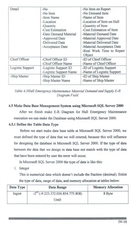
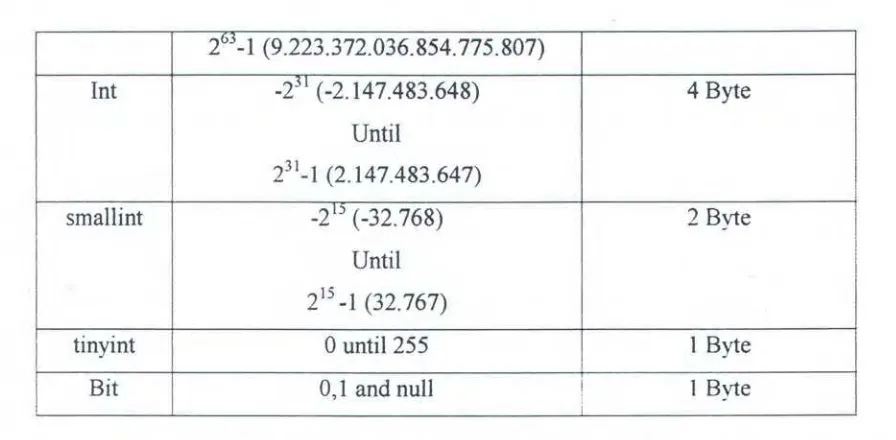
4.5. I Defme the Table Data Type IV-I6
4.5.2 Define the Table Primary Key IV-22
4.6 Make User Interface (Module) using Microsoft Visual Basic
6.0 IV-23
CHAPTER V CONCLUSION AND SUGGESTION
5 .I Conclusion
5.2 Suggestion
BIBILIOGRAPHY
APPENDIX
V-I
Picture
ENLIST PICTURE
1.1 Information Technology Exploitation in Every Era
1.2 Relation between Information System and the Environment
2.1 Relation between kinds of Maintenance
2.2 Periodical Survey Diagram For Maintenance the Class
2.3 Entity Notation
2.4 Relationship Notation
2.5 Connectivity and Cardinality Notation
2.6 Attributes Notation
2. 7 Styles ofER Notation
2.8 Example of Martin Style Er Diagram Notations
2.9 Object, Method, Property and Event Explanation
2.10 Visual Basic 6.0 Toolbox
2.11 Visual Basic 6.0 Object Properties
2.12 Example of Form That Have Been Editing
2.13 Example of Code Program (Algorithm)
2.14 Microsoft SQL Server 2000 Enterprise Manager
2.15 Microsoft SQL Server 2000 Query Analyzer
2.16 Microsoft SQL Server 2000 Service Manager
3.1 Methodology of the Research Flow Chart
3.2 Table representation ofE-R Diagram
3.3 Relation between 2 Subsystems in Hull Emergency
Maintenance Module
3.4 Data Base Subsystem
3.5 Physical table form in Microsoft SQL Server 2000
3.6 User Interface Subsystem
3. 7 User Interface Main menu create using VB 6.0
4.1 Key Maintenance Area in Meratus Shipping Company
4.3
4.4
Preparing Sequence
Execution Sequence
4.5 Controlling Sequence
4.6 Closing Sequence
4.7 Hull Emergency Maintenance Business Process in Meratus
Shipping Company
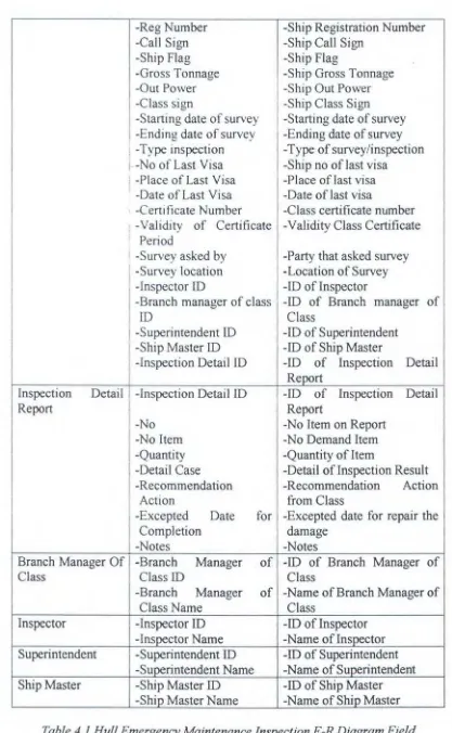
4.8 Hull Emergency Maintenance Inspection E-R Diagram
4.9 Hull Emergency Maintenance Repair List Outsource E-R
Diagram
4.10 Hull Emergency Maintenance Monitoring E-R Diagram
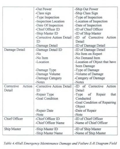
4.11 Hull Emergency Maintenance Damage and Failure E-R
Diagram
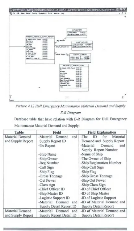
4.12 Hull Emergency Maintenance Material Demand and Supply
E-RDiagram
4.13 Ship data Table Design Using Microsoft SQL Server 2000
4.14 Hull Emergency Maintenance Inspection Table Design
Using Microsoft SQL Server 2000
4.15 Hull Emergency Maintenance Failure and Damage table
design using Microsoft SQL Server 2000
4.16 Hull Emergency Maintenance Monitoring table design
Using Microsoft SQL Server 2000
4.17 Hull Emergency Maintenance Material Demand and Supply
table design Using Microsoft SQL Server 2000
4.18 Hull Emergency Maintenance Repair List Outsource table
design Using Microsoft SQL Server 2000
4.19 Relation between primary key and foreign key in data base
4.20 Main Menu Module
4.21 Module Search Ship Data
4.22 Fill Ship Data Module
4.23 Fill Inspection Report Data Module
4.24 Fill Inspection Report Detail Data Module
4.26 Fill Inspector Data Module
4.27 Fill Damage and Failure Report Data Module
4.28 Fill Damage and Failure Detail Report Data Module
4.29 Fill Corrective Action Detail Data Module
4.30 Fill Material Demand and Supply Report Data Module
4.31 Fill Monitoring Report Data Module
4.32 Form Fill Repair List Outsource Report Data
4.33 Module Search Hull Emergency Maintenance Inspection
Detail Report Data
4.34 Module Search Hull Emergency Maintenance Damage and
Failure Report Data
4.35 Module Search Hull Emergency Material Demand and
Supply Detail Report Data
4.36 Module Search Hull Emergency Maintenance Repair Work
Detail Report Data
4.37 Module Search Hull Emergency Maintenance Repair List
Outsource Work Detail Report Data
4.38 Module Print Inspection Report
4.39 Module Print Damage and Failure Detail Report
4.40 Module Print Repair Work Detail Report
4.41 Module Print Material Demand and Supply Report
Table
ENLIST TABLE
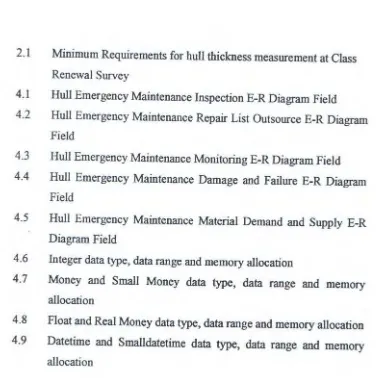
2.1 Minimum Requirements for hull thickness measurement at Class
Renewal Survey
4.1 Hull Emergency Maintenance Inspection E-R Diagram Field
4.2 Hull Emergency Maintenance Repair List Outsource E-R Diagram
Field
4.3 Hull Emergency Maintenance Monitoring E-R Diagram Field
4.4 Hull Emergency Maintenance Damage and Failure E-R Diagram
Field
4.5 Hull Emergency Maintenance Material Demand and Supply E-R
Diagram Field
4.6 Integer data type, data range and memory allocation
4.7 Money and Small Money data type, data range and memory
allocation
4.8 Float and Real Money data type, data range and memory allocation
4.9 Datetime and Smalldatetime data type, data range and memory
-1 .
r~ --·o-·~ · ~ :-::--~...
v:-:::J~u::-..=:::.- --· I I .
liS
lnstltut
1.1 Motivation
CHAPTER I
INTRODUCTION
1.1.1 Few scenes from hull emergency maintenance situation
Hull emergency maintenance plays an important part to restore the
performance and safety from a ship. Hull emergency maintenance of the
ship also cover entire aspect activity of human being to yield the production
that include a lot of related party and represents a combination of activity
that both having the character of operational and also managerial that
consisted by the activity: review, survey, check, measure, detection,
examination, repairing, material supply, data collection, analyze,
documentation, reporting, testing, recording, and auditing or verification.
Hull emergency maintenance also have the quality standard which must be
fulfilled, where in this case quality standard that expected to be fulfilled will
related by regulation class from the ship and also the regulation from the
shipping company itself
Because the number of party that be concerned, the number of a work
to do and also to ~ch of quality standard that expected, hull emergency
maintenance work will become complex and require the good planning so
can reach a maximal result. Though emulation in industry maritime in this
time progressively mount, according to Artana, (2005) maritime industry
require a new solution to:
• Improving productivity and lesser the operating expenses
• Improving quality and reliability from ship
• Fulfilling international regulation which progressively tighten
Seemly more and more challenge which must be faced in executing
hull emergency maintenance, hence there is have to be made a tool that
makes the coordination from the relevant party's become easier so the hull
emergency maintenance can execute more effective, with the development
of information technology we can use that technology to develop that tool.
Krit11i1 Maa1 lndUitrialia1ai 1 ... 1 Maaa Tranaiai
I• I
MHI Kn-ladga AKSI Selwtn&lal dan lamtllt S&IWenaalta pi capat ~atI<EPVTUSAN 01 Duat Oltn Top ~najtm•n DIDult olen Top Mau)emen HUll IWiibOrill <1111 pili &pel518115
SPE SIAl. I SASI Stall' itlll Manajtmen GirlS Kro\lltdge dl~lmpan daiEim KNOWLE!X>E ~epo&it:lrl elelrtiOnlk INFORMASI Ma naj;rnen tiAgut wngall Aru& ~t arah muu rang AMii8fi 1ang15ung ol.n amua
Mllagal pelikl5af11 lltrtalll&.lll&lllfl Mt o ... an baglan
DATA Oslm pan dat.lm bentut k.er- Dl&llllpan dalam o.ntut Mr- Akae&llllllla&darlmana &ajll; IS; dtngu atsu Urlllta& ta&; IH-Itlllft IU81i Hlpanllljl mtlllul jmngilln !lUMBER llAYAUTAMA
I~RAS1RUimJR .t.rtanm. k«@13. Danda ra S&ll!m Ttltpat JarlrQan D~ltal
PENfXCJiKANirR.NMUG Tl:la. ida'IUIOil'ltdge ubltliUln>'&tjaM rna najemen llngt,lf.tlamplr &emua k.eputut; ti:IIH dll11rapMan UngMattengan lldatada an dlamDH <lleh ptgawll
PROSES f'AifflJAN Al ur Peraklliln Me61nf:al: E-matl, Groupwart KNOWLECGE Tetr' pa~a grup lotcl-lDp PIO&e& ~ala Jar &en~ lrl olel Pro&e& beBJII -png
llellcelan-ITB!lajer •an Eitl1' Hal)'ill'illl jut an dldu kung olell perur;aha
an
I<ECEPATAN Lillllllt. lniOIIllillil11dU real UDitlCtiBf, pakeiJI bektljil c tpat. •OIMkSIIItgii:SI rulttme
tl'ne leblh ltma
Picturel.llnformation technology exploitation in every era (leebert in wiryana, 2005)
1.1.2 Ideal state of hull emergency maintenance activity
Based on situation above we offer a peripheral which is in the form of
software, so with this software is expected the coordination and decision
making of concerning hull emergency maintenance can be done in one desk
(single desktop solution). We realize for the big shipping company they
already had a system to facilitate them to conduct the preparation in
executing hull emergency maintenance, but for small and middle company a
lot of them not yet had a system which can solve hull emergency
maintenance problems in one desk (single desktop solution). In small and
middle shipping company usually the coordination between a related party
in hull emergency maintenance activity still use a manually hand written
data transfer. This situation made the preparation for hull emergency
maintenance execution take a lot of time to do. Because that reason we try to
develop our system and we expected this system can become a product
which can be sold for shipping company.
DIRECTING
···
~~
: STRATEGIC y - - ~
TACTIC
I
I
OPERATIONALI
~.,
EVALUATING CONTROLING
Picture 1.2.Relation between information s_vstem and the environment (Daihani, 2001)
Software that we develop we called it hull emergency maintenance
module. Hull emergency maintenance module will be develops
constructively using a programming language that made by Microsoft, this
programming language called visual basic 6.0. We chose this program
because software growing tends to be oriented by operating system of
windows so that software we developed is design to be work under windows
system. Visual basic 6.0 also has excess as high level programming
language so that is easy to understand and it can say that visual basic is very
structured language program. In visual basic, programmer do not only
focused just at program structure, but we can develop the creativity to design
more communicative and interesting program appearance for the user
(www.tricom.com) and for the database management system we use
Microsoft SQL Server 2000 that compatible with Visual basic 6.0.
1.2 Hypothesis and scope of problem
1.2.1 Hypothesis
An hull emergency maintenance consisted of a work that include entire
aspect activity of human being to yield the production, hull emergency
maintenance also entangle a combination work which complex enough and
claim a high quality standard which must be reached so the shipping
company can compete in industrial maritime which progressively become
more competitive. With the growth from infonnation technology at this
time, we can use help from information technology to make the hull
emergency maintenance working faster and accurate. In this research we
will made a so called software hull emergency maintenance module to facilitate
the hull emergency maintenance preparation and execution work becoming a
one desktop solution. Based on description above we can submit some
hypothesizing, there are:
1. Hull emergency maintenance module software will facilitate (make
easier) in preparing and execution of hull emergency maintenance
working
2. With the existence of hull emergency maintenance module software
we will get some of the advantage for example: assisting
management to draw up the execution of hull emergency
maintenance and chosen the right. person to executing the hull
emergency maintenance job
1.2.2 Scope of problem
· Considering the time limitation and to clarify the problem of this final
project hence we need to make definition of the following assumption and
scope of problem, there are:
1. Hull emergency maintenance module is designed for the Meratus
Shipping Company
2. Hull emergency maintenance module will relate at Class regulation
released by Biro Klasifikasi Indonesia and procedure from Meratus
Shipping Company
1.3 The aims and benefits of the research
1.3.1 The aim of the research
The aim of this research is:
1. Make software which can assist the hull emergency maintenance
process for Meratus Shipping Company
2. Make application for the hull emergency maintenance module into
hull emergency maintenance process, so is expected we get an
efficient and effective result
1.3.2 The benefits of the research
With this hull inspection module software we will be got some benefit,
that is:
1. Manage hull emergency maintenance data m a paperless,
PC-Windows based electronic format
2. Allows access to that data from multiple locations
3. Display timelines of hull emergency maintenance data, eliminating
the need to view individual listings of hull emergency maintenance
items
4. Provides an historical record of past hull emergency maintenance
dates, location and items that carried out
5. Offers easy updating of the database
6. Prints customized status reports to suit a user needs.
- .-=::--r~·lo~.s.T;::,·.__I:=:=o~~:~-·
...
1./:fr.JaO\ I
""" I 1/:f/20C'l r
'"'"
...___"""'- • 3 _..._, 3
-·
.
-
--
"""""• rH~OotUOO•lfC-1~ 'I ~~-~06IT . 1_,~7o~~
~ I ·~ I ~-· I
--
•r2
'fo,.._T;;,::,~.-~~"-•~~~ft.:~·.,~~I "~ I 1/~/20001. r ,_
...__._~ . 3
--~· 3
• ,-:=.,:_..c_t ..._... 'J ~OO><tc.a::" - ~ __,. I ~-•-•o
·--~ I
·-
1·-..:.:::-·
I-·
liS
lnstltut
2~1 General
CHAPTER IT
THEORETICAL BASED
Theoretical based represent basic theory for finishing the problems that
we analyzed or try to solve. Theoretical based cover everything that relate to
the basic theory to solve this final project.
2.2 Maintenance Management
According to BS3811 : Glossary of General Terms used in Maintenance
Organization that released by England institute of standard, express that
maintenance is a combination from various action that conducted to take care
of a tool in or improve; repair it to come up with an acceptable condition
(Corder, 1996)
According Corder, (1996) the standard quality determined by
organization that conducting maintenance. This matter differs from one
organization to another depend by its industry condition and good match for
value specified by pursuant from high standard.
The main maintenance target can be defined clearly as follows
1. To lengthen the age of asset usefulness. This matter is important especially
in developing countries because in developing country they lack of capital
resource for the replacement of tool. In developed countries sometime
more beneficial to change compare than maintaining the tool
2. For guarantee optimum availability of equipments that installed to produce
or service, and get the investment profit (return of investment) as
maximum
as
possible3. To guarantee the readiness of operational from entire equipments that
needed in every state of emergency condition, for example reserve unit,
unit of fire company and rescuer etc
4. To guarantee the safety of person that use the tools
Work of maintenance can be planned or unplanned. There's only one
maintenance form which not unplanned that is emergency maintenance, that
defined by maintenance where need an immediately executed to prevent the
serious effect, for example loss of production, big damage at equipments or
for the safety of the worker.
Planned maintenance is divided in to become two especial activities that
are preventive and corrective this two is defined clearly in BS381.
The main part preventive maintenance that covers the inspection based to
activities seeing, feel , listen and minor tuning that found require to be changed
at the time of inspection
Corrective maintenance cover the minor repair especially to short-range
which possible arise among inspection, also planned overhaul for example
annual overhaul, an extension that planned in long term detail as result from
prevention activities. The purpose of prevention activities is not just to lessen
the emergency maintenance, but also to lessen the corrective maintenance.
The relationship from kind of maintenance is described in picture below:
MAINTENANCE
J
I
I
PLANNED UNPLANNED
MAINTENANCE MAINTENANCE
I
I I
PREVENTIVE
UNPLANNED
EMERGENCYMAINTENANCE MAINTENANCE MAINTENANCE
I
RUNNING SHUTDOWN BREAKDOWN
MAINTENANCE MAINTENANCE MAINTENANCE
I
I I
RUNNING SHUIDOWN
MAINTENANCE MAINTENANCE
Picture 2.1 Relation between kinds of Maintenance (Corder, 1996)
2.3 Emergency Maintenance
Unplanned maintenance is type of maintenance which is not planned
previously so that in this case is difficult to estimating the damage of the
equipments that operating
The maintenance activity which include of this type is emergency
maintenance. Emergency maintenance is maintenance that conducted to
prevent the serious effect that probably happens.
2.4 Kind of Maintenance in Ship
Maintenance at ship is all action that conducted to maintain the ship
condition so that ready to operate and seaworthy as according to the regulation
of class and harbor-mastership. The maintenance for ship can be divided as:
I. Routine maintenance
Routine maintenance is maintenance that conducted periodically for ship
construction and also ship machinery
2. Running repair
Is repair that conducted at the time of ship is being operating. The purpose
of running repair is to take cut the time of docking execution and also for
the efficiency of expense
3. Docking
Docking of ship is executed according to the regulation from the class.
2.5 Survey and Docking Regulation According to BKI (Biro Klasifikasi
Indonesia)
Survey and docking regulation according to BKI is:
2.5.1 Periodical Survey
A. Annual surveys (seagoing ship)
According to BKJ, (2004):
a. Annual survey is survey that must be conducted for the hull,
including the anchoring equipment and the machinery, including the
electrical plant and where applicable for special equipment class at
intervals of 12 month as form date of commencement of the class
period indicated in the certificate
b. Survey period (time window): the survey has to be carried out within
±
3 months, counted from the day at which the current class periodwill complete one year of validity. For ship with accommodations for
more than 12 passengers, the annual survey has to be carried out by
no later than due date entered
c. Hull survey
1. Hull above load line include covering equipment (whether deck,
hatch cover, small hatch, watertight door, window, air pipes,
overflow pipes with their means of closure, relevant shell doors
and other openings, ventilations with their means of closure,
bulwark, guard rails, freeing port, side scuttles and deadlights,
chutes and other opening with their means of closure, cargo hold,
second deck, engine room etc, scuppers, sanitary discharge, valve
on discharge line and their control, superstructuie: deck houses
and their means of closure, general condition of mast head,
foundation of mast head and foundation of crane etc)
2. Anchoring and mooring equipment
3. All watertight doors and watertight bulkhead (if available)
4. Efficiency from manually and automation operation system from
fire door (if available)
5. Protection from fire and escape route
6. On ship equipped for carriage of containers, the annual survey
shall include random checks of:
Condition and origin/identity of (loose) lashing/securing
elements, against documentation on board (approved
container stowage plan)
Condition of container support welded into the ship structure
or the hatch covers
B. Intermediate surveys
According to BKI, (2004):
a. The intermediate surveys falls due nominally, 2.5 years after
commissioning and each class renewal and may in the case of sea
going ships be carried out on the occasion of the second or third
annual survey
b. The item that must be survey basically is same with annual survey,
with an addition:
1 . Ballast tank in ships aged 5 to 10 years, selected sea water ballast
tank are to be examined for corrosion damages and/or damages to
their coatings. Depending on the survey result, and in particular
ion the case of poor coating condition, if soft coating has been
applied, or if when built, the tanks were not provided with
effective corrosion protection, the survey is to be extended to
additional tanks of the same type.
2. If the coating in sea water ballast tank except the double bottom
tanks is found to be poor condition, but is not renewed, if soft
coating has been applied, or when built the tank were not
provided with effective corrosion protection, or if corrosion
respectively other defect are found, maintenance of class is to be
subject to the tanks in question being examined at annual
intervals, and thickness measurements carried out as considered
necessary. Also in case of the double bottom tanks, annual
surveys may have to be carried out
3 . Ballast tank in aged ten years and over, during the intermediate
survey, all sea water ballast tank are to be examined for damages
to the hull structural elements and to the coating
4. Cargo holds: depending on the ship's age and on the cargo
carried, selected cargo hold are to be closely examined in
accordance with the Surveyor' s instruction
5.
The hatches, bulkhead doors ramps, bow visors, bow, side andstem doors, etc. of all ships are to be additionally crack tested.
Essentially, the crack test will cover:
Main joining welds and their interfacial areas both on the
vessel's hull and on the visors and/or doors
~ ~
-~--Highly stressed areas in the way of the centers of rotation of
the hinges, at the Surveyor's discretion
Highly stressed areas of the locking devices and their
stoppers, at the Surveyor's discretion
Repair welding
For crack detection and dye penetrant method or the magnaflux
method are to be employed, and a test protocol is to be prepared
C. Class renewal surveys
According to BKI, (2004):
a. Class renewal surveys are to be carried out at the end of class
period for the ship's hull, including the anchoring equipment, and
the machinery, including the electrical plant, and, for any special
equipment classed
b. A class renewal survey may be carried out in several parts. The
class renewal survey may be commenced at the 4th annual survey
and must have been competed by the end of the class period. The
total survey period must not exceed 15 months
c. The class renewal survey is a rule to be held when the ship is in dry
dock or on a slipway; unless a dry docking survey has been carried
out within the admissible period. The ship is to be placed on blocks
of sufficient height so that the keel, the bottom plating and the
rudder can be examined
d. Hull survey at Class Renewal I (Age of ship up to 5 years)
1. Hull below load line (bottom plate, side shell, bow, sea chest
and their equipment, rudder and their equipment, measurement
for main rudder bearing room etc)
2. Hull above load line with their means of closure (side shell,
whether deck, hatch cover, small hatch, watertight door,
window, air pipes, overflow pipes with their means of closure,
ventilation with their means of closure, bulwark, freeing port,
guard rail, overflow pipes with their means of closure, relevant
shell doors and other openings, ventilations with their means of
closure, bulwark, guard rails, freeing port, side scuttles and
deadlights, chutes and other opening with their means of
closure, cargo hold, second deck, engine room etc, scuppers,
sanitary discharge, valve on discharge line and their control,
superstructure, deck houses and their means of closure, general
condition of mast head, foundation of mast head and
foundation of crane etc)
3. The sea water ballast tanks are to be inspected at the surveyor's
discretion. Fuel oil, lubricating oil and feed water tanks need
not to be emptied, if their tightness can be verified by an
external examination while they are completely filled and there
is no reason for doubt as to their unobjectionable condition
4. Anchoring and mooring equipment
5. All watertight door and watertight bulkhead (if available)
6. Efficiency from manually and automation operation system
from fire door (if available)
7. Protection from fire and escape route
8. The engine room structure is to be examined particular
attention to be given to tank top, shell plating in way of tank
top, brackets connecting side shell frames and tank top, and
engine room bulkheads in way of tank top and bilge well.
Where wastage is evident or suspected, thickness measurement
are to be carried out
9. On ship equipped for carriage of containers, the following
scope of survey is required for class renewal:
Checking for cracks and deformations of the container
supporting elements (welding elements) in the inner bottom
and in hatch covers, of supporting legs arranged on deck, if
any, and of the entire hatch covers
Hatch covers: checking of condition and operability of
supports and stoppers
Survey of guide rails and supporting frames if fitted
(connection to hull, deformations)
Random checking of the (loose) stowage and lashing
elements, comparison with the certificates kept in the ship's
file
10. Tightness test: each compartment of the double bottom and all
tanks, the boundary bulkheads of which form part of the main
structure of the ship, are to be subjected to a pressure test. Fuel,
lubricating oil and feed water tanks may be tested by filling
with the respective liquid
11. Thickness measurement: if the surveyors has reason to suspect
premature inadmissible corrosion, he may require the rust to be
removed from parts of the structure and thickness measurement
to be performed
e. Hull survey at Class Renewal II (Age of ship 5 to 10 years)
1. The requirements of Class Renewal II are identical to those of
Class Renewal I, however the requirement listed below are to
be observed additionally
2. The structural parts behind ceilings and insulations are to be
examined as required by the Surveyor
3. For anchor and chain cables must be calibrate, and to be ranged
so that they can be examined for wear and damages through out
their length
4. All tanks are to be examined internally, lubricating oil, fuel
tank and feed water tanks are to be subjected to random
examinations as required by the surveyor
f Hull survey at Class Renewal III (Age of ship 10 to 15 years)
1. For Class Renewals III and subsequent ones the requirement of
Class renewal II are to be complied with, however the
requirements listed below are to be observed additionally
2. Ceilings and insulations of holds are to be removed, where
necessary, to enable the condition of the bottom structure and
the inner surfaces of the shell plating of the tank tops to be
assessed. For Class Renewal IV and subsequent ones the
bottom ceiling of cargo holds are to be completely removed
and tank top is to be carefully cleaned, such as to enable proper
assessment of their condition
3. The wall lining underneath windows in the outer shell is to be
lifted as required by the surveyor so that the structure behind
may be examined
4. All tanks are to be examined internally. The fuel, lubricating oil
and feed water tanks are to be examined internally and tested to
the maximum working overpressure, at the Surveyor's
discretion.
5. The rudder body is to be examined. The connections to the
rudder stock and (if fitted) to the pintle and pertinent securing
devices are to be inspected. As far as accessible, the rudder
stock is to be surveyed. If deemed necessary in view of the
findings of the external inspection, the stock is to be
dismantled. In way of the bearings, as far as accessible, stock
and pintle are to be examined for corrosion
6. The mean diameter of the anchor chain cables is to be
determined on at least 3 links per length. The weight of the
anchors is to be checked
g. Hull survey at Class Renewal IV (Age of ship over 15 years)
1. For Class Renewals IV and subsequent ones the requirement of
Class renewal ill are to be complied with, however the
requirements listed below are to
be
observed additionally2. The bottom ceiling of cargo holds are to be completely
removed and tank top is to be carefully cleaned, such as to
enable proper assessment of their condition
3. All tank are to be tested by filling with water to the level of
overflow pipe
I. Age
:S
5Class renewal survey [No] and ship's age [year]
II. 5 < Age
:S
10 III. 10 <age:S
15 IV. Age> 15Suspect Areas throughout the vessel
One transverse Two transverse Three transverse section abreast a section in way of section m way of cargo space within cargo spaces within cargo spaces within the amidships 0,5 L the amidships 0,5 L
I
the amidships 0,5 LAll cargo hold hatch covers and coamings (plating and stiffeners)
All exposed main All exposed main deck plating within deck plating full 0,5 L amidships length
All wind and water All wind and water strakes within 0,5 L strakes full length amidships
Internals forepeak tank
m Internals m fore peak and after peak tanks
Lowest strakes m Lowest strakes and way of twin decks strakes m way of selected transverse twin decks of all bulkheads in cargo transverse
spaces together with bulkheads in cargo internal way spaces together with
internal in way Representatives exposed
superstructure deck plating (poop,
bridge, and
forecastle deck). All keel plate's full
length. Also, additional bottom
plates m way of
cofferdams,
machinery spaces
and aft end of tanks
Plating of sea
chest. Shell plating in way of over board
discharges as
considered
necessary by the
surveyors
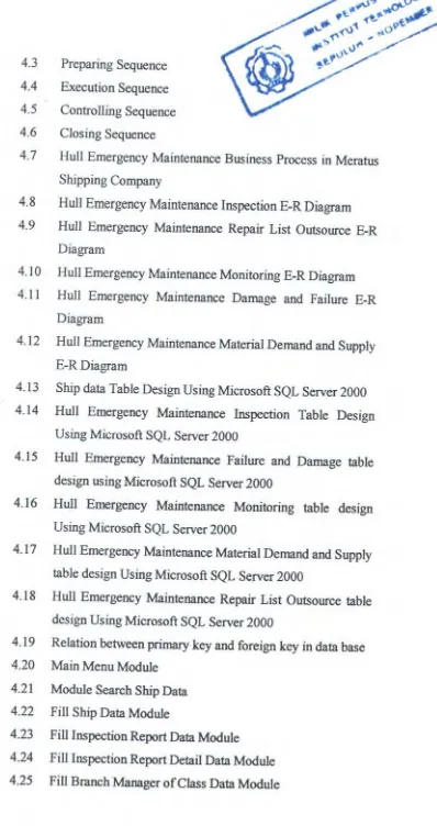
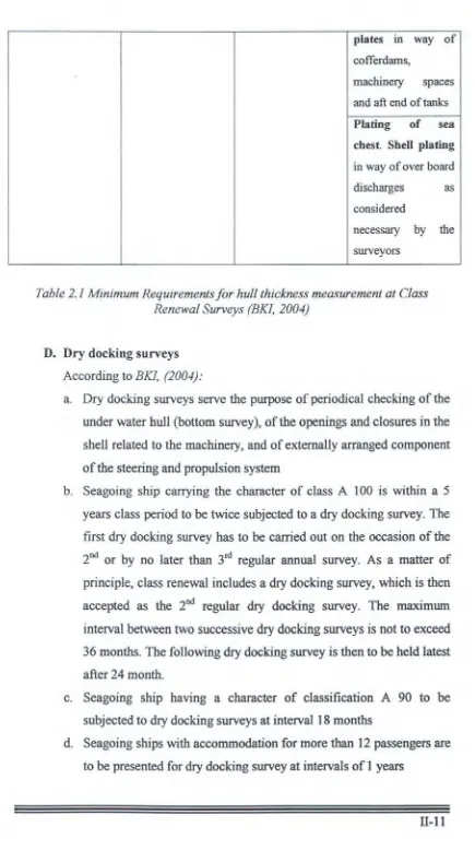
Table 2.1 Minimum Requirements for hull thickness measurement at Class Renewal Surveys (BKI, 2004)
D. Dry docking surveys
According to BKI, (2004):
a. Dry docking surveys serve the purpose of periodical checking of the
under water hull (bottom survey), of the openings and closures in the
shell related to the machinery, and of externally arranged component
of the steering and propulsion system
b. Seagoing ship carrying the character of class A 100 is within a 5
years class period to be twice subjected to a dry docking survey. The
first dry docking survey has to be carried out on the occasion of the
200 or by no later than 3rd regular annual survey. As a matter of
principle, class renewal includes a dry docking survey, which is then
accepted as the 2nd regular dry docking survey. The maximum
interval between two successive dry docking surveys is not to exceed
36 months. The following dry docking survey is then to be held latest
after 24 month.
c. Seagoing ship having a character of classification A 90 to be
subjected to dry docking surveys at interval 18 months
d. Seagoing ships with accommodation for more than 12 passengers are
to be presented for dry docking survey at intervals of 1 years
e. Hull surveys at dry docking surveys:
1. Inspection of bottom plate, side shell and the component that
stick at side shell, sea chest, rudder, ruder stock, sanitary pipe
and water drain pipes include all covering. For the third Class
renewal surveys and subsequent ones all shell plates must be take
measure for the plate thickness
2. Inspection of steering gear, include ruder, ruder flens coupling,
ruder bolt, ruder stock, pintle, ruder bearing and room for main
rudder
3. Inspection of equipment that stick at side shell like bilge keel,
shaft bracket etc.
4 . Inspection of sea chest and sea chest strainer
5. Other inspection like bow thruster tunnel etc
6. Inspection of anchoring, anchor chain cables and their equipment
(anchor and anchor chain cables must be calibrated), mooring
equipment, chain locker etc.
OS--- OS--- OS
IS---- or ----IS
ss
AS1OS= Docking Survey
SS = Special Survey (Class Renewal Survey)
AS= Annual Survey
IS
=
Intermediate surveyI
I
= 1 year periodsAS3 AS4
Picture 2.2 Periodical Survey diagram for maintenance the class (BKI, 2005)
2.5.2 Non Periodical Survey
A. Damage and repair surveys
According to BKJ, (2004):
Damage and repair survey fall due whenever the ship's hull, machinery
or electrical installations and/or some special equipment classed have
suffered a damage, which might affect the validity of the class, or if
damage may be assumed in consequence of an average or some other
event
B. Voyage repair and maintenance
According to BKI, (2004):
Where repairs to hull, machinery or equipment, which affect or may
affect classification, are to be carried out by a riding crew during a
voyage they are to be planned in advance. A complete repair procedure
including the extent of proposed repair and the need for Surveyor's
attendance during the voyage is to be submitted to and agreed upon by
the BKI reasonable in advance. Failure to notify the BKI, in advance of
the repairs, may result in suspension of the vessel's class.
The above is not intended to include maintenance and overhaul to hull,
machinery and equipment in accordance with the recommended
manufacturer' s procedures and established marine practice and which
does not require BKI approval, however, any repair as result of such
maintenance and overhauls which affects or may affect classification is
to be noted in the ship's log and submitted to the attending Surveyors for
use in determining further survey requirement.
C. Conversion surveys
According to BKJ, (2004):
In the case of conversion surveys are to be conducted in accordance with
the relevant approved particulars as in the case of new buildings
D. Occasional surveys
According to BKI, (2004):
. BKI reserve the right to reqmre Occasional Surveys to be held
independently of any regular survey. Such surveys may become
necessary for examining a vessel's technical condition and are
understood to form a part of the Society's Quality Assurance System
2.6 Computerized Maintenance Management System (CMMS)
The CMMS (in the best form) is an integrated system that helps the
maintenance leadership manages all aspects of life in the department (Levitt,
2003). According to Levitt, (1996) the reason we computerized is the same
reason we manage maintenance in the first place. We computerized to lower
or avoid costs, improve service, control cost, ensure uptime, improve quality,
etc. we also computerized because running manually looks bad in the eyes of
ours peers and ourselves (called the "because factor" by Jay Butler in the
Maintenance Management).
Some high-tech firms computerize for the last reason because
maintenance is the final department of the organization that is still done
manually. It is sobering to see the maintenance managers for some august
high-tech organization explain that they cannot get PC' s and software to help
their effort. This reinforces the belief that maintenance is a very low priority
and cannot get attention or resources for improvement.
Many maintenance departments are grappling with the decision to
computerize. It is actually a surface decision for a much deeper decision. A
decision to computerize is also a decision to threat maintenance as a serious
profession. The decision to computerize is also a decision to impose discipline
on a group of mechanics (who are traditionally very independent and hard to
control). The computer is a tool that maintenance managers imagine will allow
them to predict effect, analyze, and eventually control what goes on in
maintenance. This computerization decision and the deeper decision that it
represents go to the core of the culture of maintenance in your facility.
2.6.1 A Unified Way to Look a Potential System
According to levitt, (1996) all CMMS are designed with four major
sections or functions. It helps to separate these functions and view them one at
a time. That for major section is:
1. Part 1 - Daily Transactions: this includes all data entry such as work
order, packing slips/receipts of part, payroll information. A defect in this
section of the package is usually fatal. It is usually very difficult to repair
or reprogram this section for the vendor. The main reason that problems
here are fatal is the amount of time your staff will spend facing this
screens. The second reason is the defects here will adversely impact all
other parts of the system and may limit the usefulness the system.
2. Part 2 - Master files: The master files are the fixed information about the
assets, parts, mechanics, and organization. The master files structure
reflects the designer's biases more powerfully than any other parts of the
system.
3. Part 3 - Processing: The daily transactions are processed either in
traditional batch mode or online. Processing updates the PM schedule,
summarizes detailed repair data for reports and machine histories, and
keeps all financial accounts current.
4. Part 4 - Demands, Reports, and Inquiry Screens: The demands on a
maintenance system include reports and screens. There should be reports
when there is a large amount of data or when analysis is required. Inquiries
how you expect to use the system and then see how the system will
behave.
The following three types of reporting are commonly available.
1. Batch Level/Listing/Rehashing of Master files: This is a structured listing
of information already in the files. Report of this kind might include a
listing of all assets in the finishing department with date of purchase.
These reports are frequently required to answer corporate question about
assets, employees or other fixed information. They can save hours over
manual techniques. For the computer software vendor, these are the easiest
program to write, and they assign the lowest paid programmers to the
project.
2. Comparison, Performance, Analysis, of Database in Relationship to
Standards: This type of report is very useful for bench marking m
maintenance operation. Measures such as maintenance hours per
manufactured unit (man hours per automobile assembled or per ton of steel
rolled), maintenance dollars to parts dollars, percent overtime or percent
emergency hours can reveal the actual condition of maintenance
department. This type of reporting usually flows up to management in the
summaries of benchmarks for the whole operation. In a shop running
under the new paradigm, these benchmark numbers are made available and
discussed with all maintenance personnel.
3. Exception Reporting, Division of Report Exceeding Upper and Lower
Parameters: When you have specific questions about problem areas or
opportunities for saving, you use the parameter-driven report from this
group. You might think that the new equipment in the mold shop is
breaking down more than the older equipment. An exception report
comparing the two groups would give you the answer. Powerful
maintenance systems have industry standard query languages (such as
SQL) to allow all sort of ad hoc reporting when questions come up. The
newest systems do not require the service of a programmer for these report
(you design report as needed)
2. 7 Data Modeling
2.7.1 Data Modeling Overview
According to www.utexas.edu, (2004):
The data model is one part of the conceptual design process. The other
is the function model. The data model focuses on what data should be
stored in the database while the function model deals with how the data is
processed. To put this in the context of the relational database, the data
model is used to design the relational tables. The functional model is used to
design the queries that will access and perform operations on those tables.
Data modeling is preceded by planning and analysis. The effort
devoted to this stage is proportional to the scope of the database. The
planning and analysis of a database intended to serve the needs of an
enterprise will require more effort than one intended to serve a small
workgroup.
The information needed to build a data model is gathered during the
requirements analysis. Although not formally considered part of the data
modeling stage by some methodologies, in reality the requirements analysis
and the ER diagramming part of the data model are done at the same time.
A. Methodologies
There are two major methodologies used to create a data model:
the Entity-Relationship (ER) approach and the Object Model. In this
final project we use the Entity-Relationship approach.
B. The Aim of Data Modeling
Data modeling is probably the most labor intensive and time
consuming part of the development process. The goal of the data model
is to make sure that the all data objects required by the database are
completely and accurately represented. Because the data model uses
easily understood notations and natural language, it can be reviewed and
verified as correct by the end-users.
The data model is also detailed enough to be used by the database
developers to use as a "blueprint" for building the physical database. The
information contained in the data model will be used to define the
relational tables, primary and foreign keys, stored procedures, and
triggers. A poorly designed database will require more time in the
long-term. Without careful planning you may create a database that omits data
required to create critical reports, produces results that are incorrect or
inconsistent, and is unable to accommodate changes in the user's
requirements
C. Component of Data Modeling
The data model gets its inputs from the planning and analysis stage.
Here the modeler, along with analysts, collects information about the
requirements of the database by reviewing existing documentation and
interviewing end-users.
The data model has two outputs. The first is an entity-relationship
diagram which represents the data structures in a pictorial form. Because
the diagram is easily learned, it is valuable tool to communicate the
model to the end-user. The second comJX>nent is a data document. This
document that describes in details the data objects, relationships, and
rules required by the database. The dictionary provides the detail
required by the database developer to construct the physical database.
D. Database design Overview
Database design is defined as: "design the logical and physical
structure of one or more databases to accommodate the information
needs of the users in an organization for a defined set of applications".
The design process roughly follows five steps:
1. Planning and analysis
2. Conceptual design
3. Logical design
4. Physical design
5. Implementation
The data model is one part of the conceptual design process. The
other, typically is the functional model. The data model focuses on what
data should be stored in the database while the functional model deals
with how the data is processed To put this in the context of the
relational database, the data model is used to design the relational tables.
The functional model is used to design the queries which will access and
perform operations on those tables.
2.7.2 The Entity Relationship Model
According to www.utexas.edu, (2004):
The Entity-Relationship (ER) model was originally proposed by Peter in
1976 [Chen76] as a way to unify the network and relational database views.
Simply stated the ER model is a conceptual data model that views the real
world as entities and relationships. A basic component of the model is the
Entity-Relationship diagram which is used to visually represent data objects.
Since Chen wrote his paper the model has been extended and today it is
commonly used for database design for the database designer, the utility of
the ER model is:
• It maps well to the relational model. The constructs used in the ER
model can easily be transformed into relational tables.
• It is simple and easy to understand with a minimum of training.
Therefore, the model can be used by the database designer to
communicate the design to the end user.
• In addition, the model can be used as a design plan by the database
developer to implement a data model in specific database
management software.
E-R Diagram has some component that we must understand the
component ofE-R Diagram is:
A. Entities
Entities are the principal data object about which information is to be
collected. Entities are usually recognizable concepts, either concrete or
abstract, such as person, places, things, or events which have relevance to
the database. Some specific examples . of entities are EMPLOYEES,
PROJECTS, and INVOICES. An entity is analogous to a table in the
relational model.
Entities are classified as independent or dependent (in some
methodologies, the terms used are strong and weak, respectively). An
independent entity is one that does not rely on another for identification. A
dependent entity is one that relies on another for identification. An entity
occurrence (also called an instance) is an individual occurrence of an entity.
An occurrence is analogous to a row in the relational table.
Entities have some special type that type is:
a. Associative entities (also known as intersection entities) are entities used
to associate two or more entities in order to reconcile a many-to-many
relationship.
b. Subtypes entities are used in generalization hierarchies to represent a
subset of instances of their parent entity, called the super type, but which
have attributes or relationships that apply only to the subset.
Entity
Picture 2.3 Entity Notation (.www.smartdraw.com, 2005)
b. Relationships
A Relationship represents an association between two or more entiti
---..J
An example of a relationship would be:
-Employees are assigned to projects
-Projects have subtasks
-Departments manage one or more projects
Relationships are classified in terms of degree, connectivity, cardinality, and
existence.
Picture 2.4 RelationshipNotation (www.smartdraw.com, 2005)
c. Degree of a Relationship
The degree of a relationship is the number of entities associated with the
relationship. The n-ary relationship is the general form for degree n. Special
cases are the binary, and ternary, where the degree is 2, and 3, respectively.
Binary relationships, the association between two entities are the most
common type in the real world. A recursive binary relationship occurs when
an entity is related to itself An example might be "some employees are
married to other employees".
A ternary relationship involves three entities and is used when a binary
relationship is inadequate. Many modeling approaches recognize only binary
relationships. Ternary or n-ary relationships are decomposed into two or
more binary relationships.
d. Connectivity and Cardinality
The connectivity of a relationship describes the mapping of associated
entity instances in the relationship. The values of connectivity are "one" or
"many". The cardinality of a relationship is the actual number of related
occurrences for each of the two entities. The basic types of connectivity for
relations are: one-to-one, one-to-many, and many-to-many.
A one-to-one ( 1: 1) relationship is when at most one instance of an
entity s associated with one instance of entity B. For example, "employees in
the company are each assigned their own office. For each employee there
exists a unique office and for each office there exists a unique employee.
A one-to-many ( 1 :N) relationships is when for one instance of entity A,
there are zero, one, or many instances of entity B, but for one instance of
entity B, there is only one instance of entity A An example of a 1: N
relationships are:
-a department has many employees
-each employee is assigned to one department
A many-to-many (M:N) relationship, sometimes called non-specific, is
when for one instance of entity A, there are zero, one, or many instances of
entity B and for one instance of entity B there are zero, one, or many
instances of entity A An example is:
-employees can be assigned to no more than two projects at the same
time;
-projects must have assigned at least three employees
A single employee can be assigned too many projects; conversely, a
single project can have assigned to it many employees. Here the cardinality
for the relationship between employees and projects is two and the
cardinality between project and employee is three. Many-to-many
relationships cannot be directly translated to relational tables but instead
must be transformed into two or more one-to-many relationships using
associative entities.
Custo:mer
Account
Picture 2.5 Connectivity and Cardinality Notation (.www.smartdraw.com,
2005)
0
e. Existence
Existence denotes whether the existence of an entity instance is
dependent upon the existence of another, related, entity instance. The
existence of an entity in a relationship is defined as either mandatory or
optional. If an instance of an entity must always occur for an entity to be
included in a relationship, then it is mandatory. An example of mandatory
existence is the statement "every project must be managed by a single
department". If the instance of the entity is not required, it is optional. An
example of optional existence is the statement, "employees may be assigned
to work on projects".
f. Attributes
Attributes describe the entity of which they are associated. A particular
instance of an attribute is a value. For example, "Jane R. Hathaway" is one
value of the attribute Name. The domain of an attribute is the collection of
all possible values an attribute can have. The domain of Name is a character
string.
Attributes can be classified as identifiers or descriptors. Identifiers, more
commonly called keys, uniquely identify an