Formal Methods
Industrial Use from Model to the Code
Edited by
Apart from any fair dealing for the purposes of research or private study, or criticism or review, as permitted under the Copyright, Designs and Patents Act 1988, this publication may only be reproduced, stored or transmitted, in any form or by any means, with the prior permission in writing of the publishers, or in the case of reprographic reproduction in accordance with the terms and licenses issued by the CLA. Enquiries concerning reproduction outside these terms should be sent to the publishers at the undermentioned address:
ISTE Ltd John Wiley & Sons, Inc.
27-37 St George’s Road 111 River Street
London SW19 4EU Hoboken, NJ 07030
UK USA
www.iste.co.uk www.wiley.com
© ISTE Ltd 2012
The rights of Jean-Louis Boulanger to be identified as the author of this work have been asserted by him in accordance with the Copyright, Designs and Patents Act 1988.
____________________________________________________________________________________ Library of Congress Cataloging-in-Publication Data
Formal methods : industrial use from model to the code / edited by Jean-Louis Boulanger. p. cm. -- (Industrial implementation of formal methods series)
Includes bibliographical references and index. ISBN 978-1-84821-362-3
1. Railroads--Management--Data processing. 2. Formal methods (Computer science) 3. Application software--Development. I. Boulanger, Jean-Louis.
TF507.F66 2012 385.0285'53--dc23
2012011496 British Library Cataloguing-in-Publication Data
A CIP record for this book is available from the British Library ISBN: 978-1-84821-362-3
Introduction . . . xi
Jean-Louis BOULANGER Chapter 1. From Classic Languages to Formal Methods . . . 1
Jean-Louis BOULANGER 1.1. Introduction . . . 1
1.2. Classic development . . . 2
1.2.1. Development process . . . 2
1.2.2. Coding . . . 6
1.2.3. Specification and architecture . . . 18
1.2.4. Verification and validation (V&V) . . . 27
1.2.5. Summary . . . 33
1.3. Structured, semi-formal and/or formal methods . . . 33
1.3.1. E/E/PE system . . . 33
1.3.2. Rail sector . . . 35
1.3.3. Taking into account techniques and formal methods . . . 36
1.4. Formal methods . . . 39
1.4.1. Principles . . . 39
1.4.2. Examples of formal methods . . . 39
1.5. Conclusion . . . 45
1.6. Bibliography . . . 49
Chapter 2. Formal Method in the Railway Sector the First Complex Application: SAET-METEOR . . . 55
Jean-Louis BOULANGER 2.1. Introduction . . . 55
2.2. About SAET-METEOR . . . 56
Chapter 4. Model-Based Design Using Simulink – Modeling,
Code Generation, Verification, and Validation . . . 159
Mirko CONRADand Pieter J. MOSTERMAN 4.1. Introduction . . . 159
4.2. Embedded software development using Model-Based Design . . . 162
4.3. Case study – an electronic throttle control system . . . 164
4.4. Verification and validation of models and generated code . . . 173
4.4.1. Integrating verification and validation with Model-Based Design . . . 173
4.4.2. Design verification . . . 175
4.4.3. Reviews and static analyses at the model level . . . 175
4.4.4. Module and integration testing at the model level . . . 175
4.4.5. Code verification . . . 176
4.4.6. Back-to-back comparison testing between model and code . . . . 176
4.4.7. Measures to prevent unintended functionality . . . 176
4.5. Compliance with safety standards . . . 177
4.6. Conclusion . . . 178
4.7. Bibliography . . . 178
Chapter 5. Proving Global Properties with the Aid of the SIMULINK DESIGN VERIFIER Proof Tool . . . 183
Véronique DELEBARREand Jean-Frédéric ETIENNE 5.1. Introduction . . . 183
5.2. Formal proof or verification method . . . 184
5.2.1. Model verification . . . 186
5.2.2. Formal methods and proof of correction . . . 189
5.2.3. Combining models and proof tools . . . 192
5.3. Implementation of the SIMULINK DESIGN VERIFIER tool. . . 193
5.3.1. Reminders of the MATLAB modeling and verification environment . . . 194
5.3.2. Case study . . . 201
5.3.3. Modeling . . . 204
5.3.4. Modeling . . . 211
5.4.1. Modeling rules and convergence control . . . 211
5.6. Contributions of the methodology compared with the EN50128 normative referential . . . 220
6.2.1. Characteristics of embedded safety-critical software . . . 225
6.2.2. Architecture of an embedded safety-critical application . . . 226
6.2.3. Criticality and normative requirements for embedded safety-critical applications . . . 226
6.3.4. Synchronous formal languages dedicated to “real-time” created in laboratories . . . 230
6.5. Conclusion: extensions of languages for controllers and iterative processing . . . 240
6.5.1. Objectives . . . 240
6.5.2. Control flow . . . 241
6.6. The SCADE system . . . 246
6.8.2. Applications developed for the RATP and other French metros . . . 262
Bruno MARRE, Benjamin BIANC, Patricia MOUYand Christophe JUNKE 7.1. Introduction . . . 273
Context
Although formal analysis programming techniques (see works by Hoare [HOA 69] and Dijkstra [DIJ 75]) are relatively old, the introduction of formal methods only dates from the 1980s. These techniques enable us to analyze the behavior of a software application, described in a programming language. Program correction (good behavior, program stop, etc.) is thus demonstrated through a program proof based on the weakest precondition calculation [DIJ 76].
It took until the end of the 1990s before formal methods (Z [SPI 89], VDM [JON 90] or the B-method [ABR 96, ARA 97]) could be used in industrial applications and settings.
One of the stumbling blocks was implementing them in the framework of an industrial application (large application, cost constraints or delays, etc.). This implementation is only possible using “sufficiently” mature and high-performance tools.
Where safety requirements are critical, at least two formal methods are used: the B-method [ABR 96] and the LUSTRE language [HAL 91, ARA 97] and its graphic version, named SCADE [DOR 08]. These cover one part of the specification production process according to the code and integrate one or more verification processes.
The B-method and the SCADE environment are associated with industrial tools.
For example, Atelier B and the B-Toolkit, marketed by CLEARSY1 and B-Core2 respectively, are tools that completely cover the development cycle proposed by the B-method comprising specification, refinement, code, and proof generation. It should be noted that Atelier B3 can be accessed for free from version 4.0 onward.
Formal methods rely on different formal verification techniques such as proofs, model checking [BAI 08] and/or simulation.
The use of formal methods while in full development remains marginal, given the number of lines of code. In effect, there are currently many more Ada [ANS 83], C [ISO 99] or C++ lines of code, which have been produced manually rather than through a formal process.
That is why other formal techniques have been implemented to verify the behavior of a software application written in a programming language such as C or Ada. The technical principle known as abstract interpretation [COU 00] of programs makes it possible to evaluate all the behaviors of a software application through a static analysis. This type of technique has, in these last few years, given rise to several tools such as POLYSPACE4, Caveat5, Absint6, Frama-C7, and/or ASTREE8.
The efficacy of these static program analysis techniques has progressed greatly with the increase in power of business machines. It should be noted that these techniques generally necessitate the integration of complementary information such as pre-conditions, invariants, and/or post-conditions in the manual code.
SPARK Ada9 [BAR 03] is one approach where the Ada language [ANS 83] has been expanded to introduce these complementary elements (pre-, post-, invariant), and an adapted suite of tools has been defined.
Objective of this book
In [BOW 95, ARA 97], the first industrial feedback involving formal techniques can be found, and notably, a report on the B-method [ABR 96], the LUSTRE
1 To find out more about the CLEARSY company and Atelier B, visit www.clearsy.com. 2 The B-Toolkit was distributed by B-Core (UK) Ltd.
3 Atelier B and associated information can be obtained from www.atelierb.eu/. 4 For more information on Polyspace, visit www.mathworks.com/polyspace.
5 To find out more about Caveat, visit www-list.cea.fr/labos/fr/LSL/caveat/index.html. 6 To find out more about Absint, visit www.absint.com.
7 To find out more, visit http://frama-c.com/.
8 To find out more about ASTREE, visit www.astree.ens.fr.
language [HAL 91, ARA 97] and SAO+, the predecessor to SCADE10 [DOR 08]. Other works such as [MON 00, MON 02, HAD 06] provide a panorama of formal methods with a more scientific point of view.
Given the presentation of the context and of the state of the literature, our objective is to present concrete examples of industrial use of formal techniques.
By formal techniques, we mean the different mathematical approaches, which make it possible to demonstrate that a software application obeys some properties.
While the standard use of formal techniques consists of making specification and/or design models, they are seen by a verification subject to static analysis of code, demonstration of abiding by properties, good management of floating-point calculations, etc.
This work is related to two other books by the same authors published by ISTE and John Wiley & Sons in 2012 [BOU 12a] and [BOU 12b].
The current book is dedicated to the presentation of different formals methods, such as the B-method (Chapters 2 and 3), SCADE (Chapters 6 and 7), MATHLAB/SIMULINK (Chapters 4 and 5) and ControlBuild11 (Chapter 8).
[BOU 12a] involves industrial examples of implementation of formal techniques based on static analysis such as abstract interpretation; examples of the use of ASTREE (Chapters 2 and 3), CAVEAT (Chapter 3), CODEPEER (Chapter 6), Frama-C (Chapters 3 and 7), and POLYSPACE (Chapters 4 and 5) tools.
[BOU 12b] is dedicated to the presentation of different formal techniques, such as the SPARK Ada (Chapter 1), MaTeLo12 (Chapter 2), AltaRica (Chapter 3), Polyspace (Chapter 4), Escher verification Studio Perfect Developer (Chapter 5) and the B method (Chapters 6 and 7).
In conclusion to this introduction, I have to thank all the manufacturers who have taken the time to redraft and improve upon these chapters.
10 It should be noted that SCADE was initially a development environment basing itself on the LUSTRE language and that since version 6, SCADE has become an entirely separate language (the code generator for version 6 takes most of its input from a SCADE model, and not a LUSTRE code).
Bibliography
[ABR 96] ABRIAL J.R., The B-Book - Assigning Programs to Meanings, Cambridge University Press, Cambridge, August 1996.
[ANS 83] ANSI, Norme ANSI/MIL-STD-1815A-1983, Langage de programmation Ada, 1983.
[ARA 97] ARAGO, “Applications des méthodes formelles au logiciel”, Observatoire français des techniques avancées (OFTA), vol. 20, Masson, Paris, June 1997.
[BAI 08] BAIER C., KATOEN J.-P., Principles of Model Checking, The MIT Press, Cambridge, MA, 2008.
[BAR 03] BARNES J., High Integrity Software: The SPARK Approach to Safety and Security, Addison Wesley, Boston, 2003.
[BOU 12a] BOULANGER J.-L. (ed.), Static Analysis of Software – The Abstract Interpretation, ISTE Ltd, London and John Wiley and Sons, New York, 2012.
[BOU 12b] BOULANGER J.-L. (ed.), Industrial Use of Formal Methods, ISTE Ltd, London, John Wiley and Sons, New York, 2012.
[BOW 95] BOWEN J.P., HINCHEY H.G., Applications of Formal Methods, Prentice Hall, Upper Saddle River, 1995.
[COU 00] COUSOT P., “Interprétation abstraite”. Technique et science informatiques, vol. 19, no. 1-3, p. 155-164, Hermès, Paris, 2000.
[DIJ 75] DIJKSTRA E.W., “Guarded commands, non-determinacy and formal derivation of programs”, Communications of the ACM, vol.18, no. 8, p.453-457, August 1975.
[DIJ 76] DIJKSTRA E.W., A Discipline of Programming, Prentice Hall, Upper Saddle River, 1976.
[DOR 08] DORMOY F.-X., “Scade 6 a model based solution for safety critical software development”, Embedded Real-Time Systems Conference, 2008.
[HAD 06] HADDAD S., KORDON F., PETRUCCI L. (ed.), Méthodes formelles pour les systèmes répartis et coopératifs, Hermès, Paris, 2006.
[HAL 91] HALBWACHS N., CASPI P., RAYMOND P., PILAUD D., “The synchronous dataflow programming language lustre”, Proceedings of the IEEE, vol. 79, no. 9, p. 1305-1320, September 1991.
[HOA 69] HOARE C.A.R, “An axiomatic basis for computer programming”, Communications of the ACM, vol. 12, no. 10, p. 576-580-583, 1969.
[JON 90] JONES C.B., Systematic Software Development using VDM, Prentice Hall International, Upper Saddle River, 1990.
[MON 00] MONIN J.-F., Introduction aux méthodes formelles, préface by HUET G., Hermès, Paris, 2000.
[MON 02] MONIN J.-F., Understanding Formal Methods, preface by HUET, G., TRAD. M., Hinchey, Springer Verlag, New York, 2002.
From Classic Languages
to Formal Methods
1.1. Introduction
The introduction to this book has provided the opportunity to set formal analysis techniques in a general context. In this chapter, we are going to focus on formal methods and their implementation.
The classic development process of a software application is based on the use of a programming language (for example, Ada [ANS 83], C [ISO 99] and/or C++ [ISO 03]). These languages have a certain abstraction level in comparison to the code finally executed on the computer, a program is a set of line of code write manually.
The size of applications has gone from several thousands of lines to several hundreds of thousands of lines of code (possibly several millions for new applications). Considering the number of faults introduced by developers, it is then important to use techniques to limit the number of faults introduced and to more easily identify potential faults.
As we will show later, formal methods enable us to fulfill this double objective.
1.2. Classic development
The objective of this section is to analyze the weaknesses of theclassic(meaning non-formal) process, which is implemented to make a software application.
1.2.1.Development process 1.2.1.1.Presentation
The creation of a software application is broken down into stages (specification, design, coding, tests, etc.). We refer to the lifecycle. The lifecycle is necessary to describe the dependencies and sequencing between activities.
Functional
Figure 1.1.Three possible lifecycles
The lifecycle must take into account the progressive refinement aspect of the development as well as possible iterations. In this section, we present the lifecycle, which is used to make a software application.
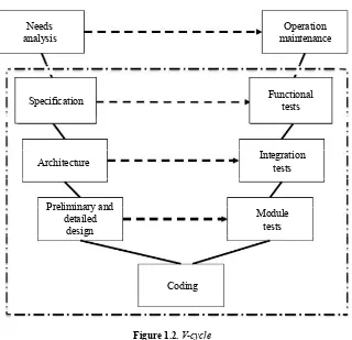
As Figure 1.1 shows, there are several cycles: a) V-cycle, b) waterfall cycle, c) spiral cycle, etc. for making a software application, but the cycle recommended by different standards (CENELEC EN 50128 [CEN 01], DO 178 [ARI 92], IEC 61508 [IEC 98], ISO 26262 [ISO 09]) remains the V-cycle.
the software must do (and not how it will do it). In the context of architecture definition, the aim is create a hierarchical breakdown of the software application into modules/components and to identify interfaces between these elements.
Needs
analysis maintenanceOperation
Specification
Architecture
Functional tests
Integration tests
Module tests Preliminary and
detailed design
Coding
Figure 1.2.V-cycle
Description of each module/component (data, algorithms, etc.) is achieved within the framework of the design. The design phase is often separated into two stages. The first stage, named preliminary design, aims to identify manipulated data and necessary services; the second stage, named detailed design, aims to describe all services through their algorithms. The design phase then gives rise to the coding phase.
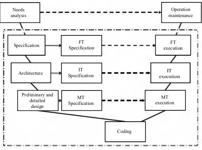
There is a horizontal correspondence (dotted arrow) between activity specification and design and activity testing. The V-cycle is thus broken down into two phases: bottom-up phase and top-down phase. Top-down phase activity (execution of the MT/IT and FT) must be processed during the bottom-up phase. Figure 1.3 is thus closer to the V-cycle recommended.
Specification SpecificationFT executionFT
Preliminary and detailed
design
IT execution Architecture
MT Specification
IT Specification
Operation maintenance Needs
analysis
MT execution
Coding
Figure 1.3.V-cycle including test specifications
1.2.1.2.Advantages/disadvantages
The V-cycle of Figure 1.3 reveals that faults introduced in the making of the software application will be detected during the top-down phase, which has a direct impact on the cost and delays of making the software.
Experience in safety-critical applications shows that activity testing accounts for 50% to 75% of the cost of production and that the presence of faults can multiply delays in production two or three times over.
of corrections and verification of corrections (in general, verifying correct implementation of modifications is achieved through test runs, but it will be necessary to verify that no additional modification has been implemented).
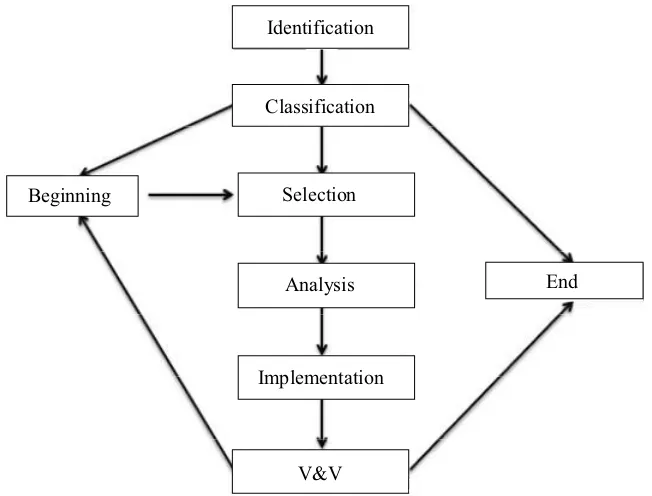
Analysis of anomalies is achieved through an impact analysis (definition 1.1) and a non-regression analysis (definition 1.2). In certain cases, non-regression is said to be total, and for this, it is necessary to re-execute the series of tests on one phase or all phases.
The objective of non-regression analysis is to minimize the cost of a new version.
DEFINITION 1.1.– IMPACT ANALYSIS. Impact analysis of an anomaly consists of identifying modifications to make in the bottom-up phase (impact on the documents, impact on the code, impact on the description and test implementations) of production.
DEFINITION 1.2.– NON-REGRESSIONANALYSIS. Non-regression analysis consists of determining a series of tests, which make it possible to demonstrate that the modification made has not had an effect on the rest of the software application1.
In addition, it should be noted that the cost of correcting a fault is directly linked to the phase during which it is identified. In effect, detecting a fault during the functional testing phase is 10 to 100 times more expensive (not to mention higher in certain cases) than a fault identified in the module testing phase. This cost is linked to resources that have been used right up to discovery of the fault and to the difficulty of carrying out functional testing (usage of targeting equipment, necessity of taking real time into account, difficulty of observation, technical expertise of people involved, etc.).
Our experience feedback (in a railway system2evaluator/certifier capacity) leads us to conclude that the unitary and integration testing phases are not effective, given that manufacturers consider that:
– module testing is useless (as a general rule, module tests are defined from the code);
– software/software integration is reduced to a big-bang integration (integration of all the code in place of a module-by-module integration); at worst, all the code is compiled suddenly and integration is reduced to an interface verification by the compiler;
1 It should be noted that a non-regression analysis can be carried out on a software application or on a more important element such as equipment, a subsystem, and/or a system.
– software/hardware integration is supported by functional testing on a target. If all of the software is being executed correctly on the target machine, the integration is correct.
Classification
Selection
Analysis
Implementation
V&V
End Beginning
Identification
Figure 1.4.Cycle management of anomalies
Cost and delay management imply two necessities:
– N.1: reducing the number of faults introduced into the application during the bottom-up phase of the V-cycle;
– N.2: identifying faults introduced within the software application as early as possible.
1.2.2.Coding 1.2.2.1.Presentation
Even if these languages have a certain abstraction level with respect to the code ultimately executed on the computer, they necessitate the writing of a line of code.
It is not possible to analyze all the current programming languages for all industries. We shall analyze the advancements that have taken place in the rail sector.
1.2.2.2.Assessment
1.2.2.2.1. The Ada language
The first rail applications in France were programmed in the middle of the 1980s with the Modula 2 language. Since then however, the Ada 83 language [ANS 83] has become the reference language for the development of safety-critical applications [RIC 94].
As Table 1.1 shows, in the context of applications that have a high level of criticality (SSIL3/SSIL4), the Ada language is only R (recommended); it is necessary to establish a sub-assembly of the language so that use of Ada be HR (highly recommended).
C or C++ without restriction Sub-assembl y of C or C++
SSIL04 SSIL1 SSIL2 SSIL3 SSIL4
SSILO3
Table 1.1.CENELEC EN 50128 [CEN 01] – Table A.154
Ada was designed on the initiative of the DoD (the US Department of Defense) to federate more than 400 languages or dialects used by this body since the 1970s.
Ada is very widely used in the framework of embedded software applications in avionics (airbus), the space (the Ariane rocket), and the rail sector. The principal characteristic of these systems is that they require a correction of the execution.
The Ada 83 language [ANS 83] has advanced toward a second major standard, Ada 95 [ISO 95], which is the first object-normalized language. It provides the possibility of constructing object-oriented models. The latest version to date is called Ada 2005.
Figure 1.5.Example of Ada code
DEFINITION 1.3.– CERTIFICATION. Certification consists of achieving a certificate, which is a commitment that the product complies with a normative referential. Certification is based on the results of an evaluation and on production of a certificate.
Regarding certification (see definition 1.3) of Ada compilers, the existence of a standard and of a semantic of Ada has made it possible to define a compiler certification process.
This process has been implemented on different compilers and is based on a suite of tests named ACATS (Ada Conformity Assessment Test Suite); see the [ISO 99a] standard. To find out more, consult [ADA 01].
At present, these new versions of Ada have not been adopted by the embedded systems sector, because of their object-oriented aspect.
Given their efficacy, however, Ada 95 compilers are used for compilation provided that a sub-assembly of the language, which does not use the “object-oriented” features is relied upon.
John Barnes, in the context of the AdaCore article makes a presentation on the strength of the Ada 2005 language (syntax and semantics, strong typing, sound management of the pointer and the memory, etc.) and the impact of its implementation to demonstrate that the software is reliable.
The “object-oriented” aspect is not taken into account by the CENELEC EN 50128 ([CEN 01], DO 178 [ARI 92], CEI/IEC 61508 [IEC 98], ISO 26262 [ISO 09]) standards applicable to safety-critical applications.
(programming style), which enable creation of a supposedly-certifiable application (see definition 1.4).
DEFINITION1.4.– CERTIFIABLEAPPLICATION. A certifiable software application is a software application that has been created to be certified.
The SPARK Ada language [BAR 03] is a programming language, which is a sub-assembly of Ada. All the complex structures of Ada regarded as risky or not allowing for an easy safety demonstration are not to be found in SPARK Ada. A mechanism enabling the addition of annotations in the code has been introduced.
SPARK Ada tools contain a compiler, but also a verifier for annotations. There is a free version of the SPARK Ada tools4. Chapter 1 of a future book by the same authors (to appear in 2012) will provide the opportunity to present the SPARK Ada tool as well as some industrial examples of its implementation.
1.2.2.2.2. The C language
The C5language [KER 88] was one of the first languages to be made available to developers to create complex applications. The principal difficulty of C resides in the partial definition of the language, which means that different compilers generate one executable with different behaviors. It has since been subject to a standardization process by the ANSI [ISO 99].
Regarding the use of the C language [ISO 99], contingent upon the safety level required, the CENELEC EN 50128 [CEN 01] standard recommends defining a sub-assembly of the language (see Table 1.1), the execution of which is controllable.
Table 1.2 (an extract from the new version of the CENELEC EN 50128 [CEN 11] standard) shows that there was sufficient experience feedback for the Ada, C and C++ languages, enabling no further explicit mention of the notion of sub-assembly of the language as it is taken as established.
Figure 1.6 presents a piece of C code, which can give two different codes contingent upon anomaly (a) or (b) that is implemented.
This example emphasizes the weaknesses of the C language, small programming errors that are not detected in the compilation. It should be noted that this type of error is detected if the programming language used is Ada.
4 To find out more about AdaCore and free tools such as GNAT and SPARK Ada, visit: www.libre.adacore.com.
C or C++
Table 1.2.New CENELEC EN 50128 [CEN 11] – Table A.15 (partial)
Certain weaknesses of C may be overcome by implementing some programming rules; by way of an example, to avoid an anomaly of the type if (a = cond) instead of if (a == cond), a rule of the following form can be implemented: “in the framework of comparison with a variable, this must be in the left part of the expression”.
From 1994, some experience feedback regarding the implementation of C (see for example [HAT 94]) has revealed that it was possible to define a sub-assembly of C usable to create software applications needing a high level of safety (SSIL3, SSIL4).
In fact, since the end of the 1990s, the MISRA-C [MIS 98, MIS 04] standard, which was developed by the Motor Industry Software Reliability Association (MISRA6), has become a standard for the C language.
Being that the C
fragment of program is as follows
failure
failure
Figure 1.6.Example7of a fault in C
MISRA-C [MIS 04] specifies some programming rules (see the examples of Table 1.3) making it possible to avoid execution errors provoked by poorly defined constructions, unforeseen behaviors (certain C language structures are not completely defined) and misunderstandings between those people in charge of production (legible code, code with implicit cast, etc.). Several tools enable the MISRA-C rules to be automatically verified.
The MISRA-C [MIS 04] standard repeats some rules, which are explicit in several standards (see for example 14.4 and 14.7):
– rule 14.4: in the EN 50128 standard – Table A.12 or the IEC 61508 standard – Table B.1;
– rule 14.7: in the EN 50128 standard – Table A.20 or the IEC 61508 standard – Table B.9;
– etc.
MISRA-C [MIS 98] was created in 1998 and updated in 2004 [MIS 04], which shows that some experience feedback has been made use of.
Rule 1.1
All of the code must conform to the ISO 9899:1990
norm “Programming languages – C”, amended and corrected by ISO/IEC9899/COR1: 1995, ISO/IEC/9899/AMD1: 1995 and ISO/IEC9899/COR2: 1996.
Each tag is a single identifier. There must not be any dead cod.
The pointer arithmetic can only be used for pointers which address a table or tabular element.
An object declaration must not contain more than two levels of pointer indirection
A function must have a single output point at the end of the function.
No unconditional jumps (goto) in programs. Status8
There must not be any dead code.
Table 1.3.Some MISRA-C: 2004 [MIS 04] rules9
The principal difficulty of C remains the choice of a compiler having sufficient experience feedback at its disposal for the chosen target and safety level to be achieved.
In the absence of a precise and complete standard, there is currently no certification process for C compilers, even though there are initiatives such as [LER 09]9.
1.2.2.2.3. Object-oriented language
As already stated, the “object-oriented” aspect is not taken into account by the CENELEC EN 50128 ([CEN 01], DO 178 [ARI 92], CEI/IEC 61508 [IEC 98], ISO 26262 [ISO 09]) standards applicable to safety-critical applications.
The “object-oriented” aspect is cited in the CENELEC EN 50128 [CEN 01] standard, but the constraints applying to languages do not allow for development of a safety-critical application (SSIL3 and SSIL4) with this type of language (see Table 1.4). SSIL0 SSIL1 SSIL2 SSIL3 SSIL4
Table 1.4.CENELEC EN 50128 [CEN 01] – Table A.12
As shown by Tables 1.1 and 1.2, the C++ language [ISO 03] is cited as applicable but certain recommendations are not compatible with the use of an object-oriented language, as shown in Table 1.4.
C++ was developed during the 1980s; it proceeded from an improvement of the C language. C++ introduces the notion of class, inheritance, virtual functions, and overload. It was standardized by the ISO in 1998 and in 2003 [ISO 03].
Since the beginning of the 2000s, many attempts have been made to define a framework enabling the use of the C++ language for the development of high-safety level applications (SSIL3, SSIL4). The following works can be cited:
– JSF++ (Join Strike Fighter C++), which has published a guide [LOC 05] regarding the current work, notably the MISRA-C: 1998 [MIS 98] standard;
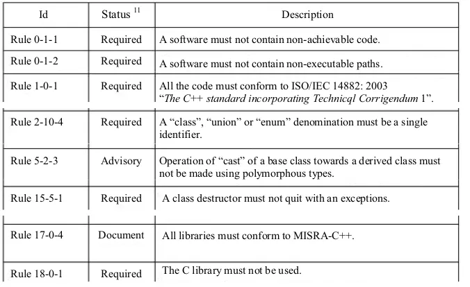
– MISRA, which has developed the MISRA-C++: 2008 [MIS 08] standard; Table 1.5 shows some MISRA-C++: 2008 rule examples;
– OOTIA10 (Object Oriented Technology in Aviation), which has published several guides [OOT 04a, OOT 04b, OOT 04c, OOT 04d].
Rule 0-1-1
A software must not contain non-achievable code. A software must not contain non-executable paths. All the code must conform to ISO/IEC 14882: 2003 “The C++standard incorporating Technicql Corrigendum1”. A “class”, “union” or “enum” denomination must be a single identifier.
Operation of “cast” of a base class towards a derived class must not be made using polymorphous types.
A class destructor must not quit with an exceptions.
All libraries must conform to MISRA-C++.
The C library must not be used. Status11
12Table 1.5.Some MISRA-C++: 2008 [MIS 08] rules12
C++ [ISO 03] is therefore quite an old language. Some approaches identifying the weak points of C++ and proposing some rules appeared quite early on [MEY 98, SUT 05], but the definition of a framework for using C++ for high safety-level applications is quite recent [OOT 04, LM 05, MIS 08], which explains how applications in C++ are to be found even at SSIL2.
As Table 1.5 shows, the MISRA C++: 2008 [MIS 08] standard introduces some rules inspired by those current for the C language, but which do not allow for all the difficulties of C++ to be taken into account.
10 To find out more, visit: www.faa.gov/aircraft/air_cert/design_approvals/air_software/oot. 11 A MISRA rule may be “required”, “advisory”, or “document”. A “required” rule must mandatorily be implemented by the developer, an “advisory” rule cannot be disregarded, even if it is not mandatory to implement it and a “document” rule is mandatory.
Under various pressures (a reduction in the number of Ada and C programmers, for example), the updating of standards such as CENELEC EN 50128 or D0 178 has given rise to initiatives seeking to introduce object-oriented languages.
The classes should only have a single objective.
Inheritance used only if the derived class is a refinement of its base class.
Depth of inheritance limited by coding norms.
Neutralization of operations (methods) under strict control.
Multiple inheritance used only for interface classes. SSSSIILLOO SSSSIILL11 SSSSIILL22 SSSSIILL33 SSSSIILL44
Table 1.6.New CENELEC EN 50128 [CEN 11] – Table A.23
Thus, the new version of the CENELEC EN 50128 [CEN 11] standard has expanded the list of usable object-oriented languages to JAVA and to C#, as Table 1.2 shows. Yet this new version of the standard introduces some restrictions (limitations on inheritance) as Table 1.6 shows.
The C version of the D0 178 standard should use a specific annex aiming to define the constraints of implementing an object-oriented language for production of a safety-critical application.
As for C, the difficult point with C++ remains the demonstration that the compiler for the chosen target and associated libraries complies with the safety objectives, which have been defined by safety studies. As there is currently no certification for C++ compilers, it will be necessary to establish a justification based on experience feedback and/or qualification.
1.2.2.3.Programmable controller
The “continuous processes” CEI/IEC 61511 [IEC 05] industry standard brings precision in restricting the initial field of application of the CEI/IEC 6150813 [IEC 98] standard to the traditional context of continuous processes.
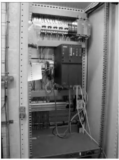
Figure 1.7.Example14of an actual programmable controller
The CEI/IEC 61511 [IEC 05] standard applies in the framework of E/E/PE systems in the context of safety instrumented functions for controlling a process (chemical products, petrol refining, petrol and gas production, non-nuclear electricity production). It does not apply to manufacturers or system providers, who must use the CEI/IEC 61508 standard.
For synthesizing, the CEI/IEC 61511 standard is used when already-certified components (of programmable controllers) are used and when they are programmed with limited variability languages.
of implementation of a programmable safety controller for managing ventilation of the Soumagne tunnel and the Walhorn trench of the high-speed L3 line.
With respect to programming languages, the CEI/IEC 61511 [IEC 05] standard only concerns programming languages usual to the industry, which are specified through the CEI/IEC 61131-3 [IEC 03] standard.
This in no way prevents anyone from programming their E/E/PE system with the Ada or C++ languages, but in these cases, it is necessary to refer to the CEI/IEC 61508 [IEC 98] standard, which defines how these languages can be used.
Part 3 of the CEI/IEC 61131-3 [IEC 03] standard describes the principles for producing an application for a programmable controller and introduces several technical terms: FBDs for functional block diagrams, SFCs for sequential function charts, suites of instructions (written IL), structured text (ST), and contact diagrams (LD forladder diagrams).
The languages introduced by the CEI/IEC 61131-3 [IEC 03] standard are used more and more for making software applications, as these graphic languages are easily assimilated and standardized. There are thus some tools which cover all the formalisms described in the CEI/IEC 61131-3 [IEC 03] standard.
One of the important points regarding these tools is that they are supplied for making programmable controller applications and may thus come with a certificate for a safety level, which might be SSIL2 or SSIL3.
The ControlBuild tool is presented in Chapter 4 of this book. ControlBuild is used by several actors in the rail sector to make SSIL2-level safety-critical software applications.
1.2.2.4.Qualification
The different standards (DO 178, ISO 26262, and CENELEC EN 50128) reveal/or will reveal the notion of the “qualification file”.
Qualification of a tool depends on its impact on the final product: – an impact on the executable (compiler, data generator, etc.); – an impact on the verification and/or validation (test tools, etc.); – no impact.
The qualification file can rely on different activity types:
– experience feedback construction: an inventory of all uses (those that are known and those of the business). It must then be capable of justifying the version used, levels of safety, size, sectors, etc.;
– establishment of a qualification; test runs of the tool can be undertaken so as to show that the former is usable for a given safety level.
The notion of qualification is an important notion, which is linked to implementation of tools in the production process of a software application.
All tools used can be subjected to a qualification phase.
Regarding formal methods, the question of qualification of tools is of fundamental importance, since the complexity of technologies implemented (prover, model-checking, etc.), the confidentiality aspect (licensed algorithm, etc.), the innovation aspect (new technology, few users, etc.), and the maturity aspect (product resulting from research, product made using a “free” license, etc.) do not permit trust to be built easily.
1.2.2.5.Advantages/disadvantages
The programming language used must facilitate anomaly detection and for this, it is necessary to implement strong typing and modular and structured programming.
Adequate programming language Strongly typed programming language Sub-assembly of the language
Certified translator
Translator: confidence has been increased as a result of use
Library of modules software and proven/verified components
Tools: confidence in which has increased as a result of use
– N.3: necessitates definition of a sub-assembly of the language (limiting the difficulties) and using a set of design and coding rules;
– N.4: necessitates using sufficient experience feedback to show that the tools and the compiler especially, are usable for the expected safety level.
1.2.3.Specification and architecture 1.2.3.1.Requirements management
The standards applicable in different industries render identification of the software application requirements mandatory. It should be noted that the literature presents several terms: prescriptions, recommendation, requirement, constraint and property, which seem equivalent. The generalist CEI/IEC 61508 [IEC 98] standard uses the notion of prescription, but the most-used term remains the notion of requirement.
Requirements
Functional requirements
Non-functional requirements
Performances
FMDS
Figure 1.8.Different types of requirements
As Figure 1.8 shows, the requirements are of at least two types: functional and non-functional requirements (safety, reliability, performance, etc.).
In Chapter 2 of [RAM 09] and Chapter 3 of [RAM 11], we have presented some examples of requirements management in the automobile and rail industries.
Table 1.8 is an extract from [STA 94], which shows that over 43% of the causes of failure in production originate from incomplete requirements, something lack in the needs description and unrealistic expectations.
Definition of a minimal set of requirements makes it possible to have a basis that can be managed, the tool then being a communication vector between teams.
13.1%
Didn’t need it any longer
Table 1.8.Distribution of the causes of failure
The difficulty then resides in defining the notion of requirement. There are currently several studies, which attempt to identify what a requirement is and how to take it into account. [HUL 05] features one of the most complete summaries. We will recall the following definition, which has resulted from studies carried out by manufacturers.
DEFINITION 1.5.– REQUIREMENT. A requirement is a formulation that translates a need and/or some constraints (technical, costs, delays, etc.). This formulation is written in a language that may be natural, mathematical, etc15.
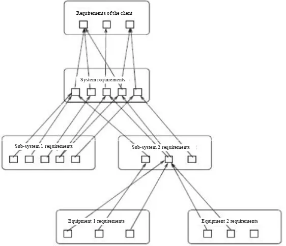
Figure 1.9 shows how the recommendations of the client can be declined on the system and how processing can continue right down to the software and hardware type elements.
In the context of the verification phase of level ni, it is necessary to show that the requirements of this level are in relation to the higher ni−1level. The links between requirements of different levels are made during a phase of traceability.
Implementation of traceability involves defining at least one link between two objects. In the context of the requirements, traceability links must make it possible to show that an ni-level requirement is linked to a need of the preceding ni−1level.
The inverse link makes it possible to show that no requirement has been forgotten during the production process.
As Figure 1.10 shows, there are currently several basis transformations of requirements. Among these, two cases are particularly interesting; the addition and the abandonment of a requirement; in both cases, it is absolutely necessary to attach a justification to the requirement.
Requirements of the client
System requirements
Sub-system 1 requirements Sub-system 2 requirements
Equipment 2 requirements Equipment 1 requirements
Figure 1.9.Partial traceability between the requirements of the client and requirements linked to the equipment
1.2.3.2.Specification
The specification of a software application is thus at the very least, a set of requirements. A first analysis of the specifications provided by the client must make it possible to identify functional needs. Figure 1.11 presents the proposed process.
Safety analysis Specifications
Functional needs Extra-functional needs
Development process of the specification
Specifications
Figure 1.11.Development of the specification
In parallel with this work, it is possible to begin analyses linked to dependability, the objective of which is to define the non-functional requirements: safety requirements but also availability, reliability or other requirements.
It is, however, necessary to know a bit more about the needs of the software application. Within the application, it is thus necessary to introduce:
– interfaces with the environment;
– the notion of state in establishing a partition between safe functioning, decline and dangerous states;
– the notion of correct behavior and of dangerous behavior;
– the notion of requirement linked to safety; this type of requirement must allow for characterization of dangerous behaviors;
– the integrity level of the software (written SSIL/DAL).
Figure 1.12 reveals a software application environment, which is composed of three entries (Ei), two exits (Sj), and three interfaces (Ik) with the hardware resources (for example, access to a specific memory address).
E1
Figure 1.12.Software application environment
Standards recommend that the specification of a software application be composed from a textual description of the need (the requirements) and all the notations necessary for facilitating understanding of the need. So, for the EN 50128 [CEN 01] standard, there is Table A.2 (Table 1.9).
Formal methods comprising for example, CCS, CSP, HOL, LOTOS, OBJ, VDM, Z, B SSIL0SSIL0 SSIL1SSIL1 SSIL2SSIL2 SSIL3SSIL3 SSIL4SSIL4
Table 1.9.CENELEC EN 50128 [CEN 01] – Table A.2
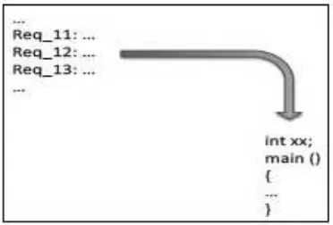
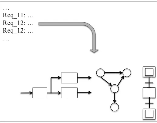
Figure 1.13.From the requirements to the code
Successful development of a maintainable software application consists of going through at least two stages:
–a formalization of the requirements phase(see Figure 1.15). This formalization phase can rely on structured methods (for example, Figure 1.14 in SADT16makes it possible to establish a functional analysis, etc.), on semi-formal or formal methods (controller, Petri net, Grafcet, B-method17, SCADE18, etc.);
–an architecture phase(see section 1.2.3.3).
Train
activation displacementTrain 1
Train 2 displacement
Train deactivation Continued processing Activation Cycle
Figure 1.14.Example of static introducing different types of communication
16 The acronym SADT stands forStructured Analysis and Design Technic. This method was invented by the Softech company in the US. The SADT method is a method of analysis by successive levels of descriptive approach of a set, whatever it may be.
17 In Chapter 2, we present an example of the use of SADT [LIS 90] and of the B-method [ABR 96, BEH 96] in the context of the SAET-METEOR project [BOU 06].
The formalization phase is important because it enables translation of an abstract requirement into modeled elements, like the following P1 property:
P1: “there must not be any risk of collision”
which can be translated into set-theoretic logic of the first order in {t1,t2} [T], hence Dt1∩Dt2=φ,if t1≠t2, withDti,which is the domain of train speed i and [T], which is the whole set of trains.
…
Req_11: … Req_12: … Req_12: … …
Figure 1.15.Formalization of requirements
1.2.3.3.Architecture
Once the software application specification is created, it is then possible to establish an architecture. This architecture aims to break down the software application into components19(or modules, following the vocabulary used).
Figure 1.16 presents an example of architecture. The software application has been broken down into three components (C1, C2, and C3); there are interfaces between the environment (E1, E2, S1, S2) and components and some interfaces between components; for each component, the list of requirements to take into account is given.
Figure 1.16.Example of software application architecture
1.2.3.4.Model
The new version of the EN 50128 [CEN 11] standard (Table A.3) recommends that software application architecture is based a structured method (SADT, etc.).
Yet it is possible to establish a model that is based on the techniques of Table A.17 (see Table 1.10).
Data modeling
SSILO SSIL1 SSIL2 SSIL3 SSIL4
Data organization
Table 1.10.New CENELEC EN 50128 [CEN 01] – Table A.17
The creation of an M model is a means of understanding and/or stopping a problem/situation. In general, the specification phase, which allows for adaptation of the specifications, involves creation of an M model.
A model may be more or less close to the system studied, which would then be termed abstraction. The closer the model is, the closer the results obtained will be to those observed on the final system.
The presence of a semantic enables implementation of reasoning techniques, which guarantee correction of obtained results.
A model (Figure 1.17) is, in general, composed of two complementary parts: – a static model (Figures 1.14 and 1.16) describing the entities constituting the system and the states that can be associated with them;
– a dynamic model describing authorized changes of state.
Figure 1.17 presents an example of a UML model20[OMG 06a, OMG 06b], and [OMG 07] of a rail system implementing different models: use case, sequence diagram, state/transition diagram, and class diagram.
High speed
train Low speedtrain Package Train
Speed Start Accelerate Deccelerate
Wagon
Stop Start
Train Conductor
Conductor
Start Start
Start the train
Physical train
Start Accelerate
Accelerate speed = speed+x
Deccelerate [speed 0] Deccelerate [speed/= 0] System
Figure 1.17.Example of a UML model
Using UML notation is thus not without certain questions [BOU 07, OKA 07]. How can we use a notation without a semantic? How can we evaluate an application based on UM notation? etc. Several studies aim to offer answers to these questions, for example [OOT 04, MOT 05].
At present, UML notation [OMG 06a, OMG 06b, OMG 07] is not recognized as a structured and/or semi-formal method in the standards, although many would like to implement it completely or partially.
In [BOU 07, BOU 09a] and Chapter 19 of [RAM 09], we have shown how UML notation can be used to create some models of safety-critical systems.
In the context of the RT3-TUCS, ANR-SAFECODE, and ANR-RNTL-MEMVATEX projects, we have studied different ways of introducing UML as a means of modeling a safety-critical system; see for example [RAS 08, BOU 08, IDA 07a, IDA 07b, OKA 07, BOU 05].
In recent years, several studies have enabled a formalization of UML notation to be proposed through returning to formal languages, for example [IDA 09, IDA 06, MAR 04, MAR 01, MAM 01, LED 01]. Works such as [MOT 05] must also be noted, which have made it possible to suggest some additional rules for verifying UML models.
1.2.3.5.Advantages/disadvantages
A specification and/or architecture cannot be reduced to a list of requirements; it is necessary to use a supporting model of requirements. This supporting model (see Table 1.10) will make it possible to verify the coherence and completion of requirements. Creation of a software application specification and/or architecture (though the same could be said of the design phase) entails:
– N.5: creating a model associated with the requirements;
– N.6: having a method of verifying the model so as to verify the coherence and/or completion of the requirements;
– N.7: being able to continue processing (Figure 1.18) of the specification phase up to the design phase; not to mention the coding phase.
1.2.4.Verification and validation (V&V) 1.2.4.1.Presentation
…
Req_11: … Req_12: … Req_13: … …
Figure 1.18.From the requirements to the architecture
Achievement of a quality standard requires demonstration that: – no fault has been introduced during the design;
– the product corresponds to the needs that have been identified.
Above all else, it is necessary for us to recall what verification and validation are.
DEFINITION 1.6.– VERIFICATION. Confirmation by tangible proof that the specified requirements have been met at each stage of the production process.
DEFINITION 1.7.– VALIDATION. Confirmation by tangible proof that the anticipated requirements for a specific use or application have been met.
The two preceding definitions are extracts from the ISO 9000:2008 standard (see [ISO 08]). They introduce the notions of requirements and of proof.
– verification ensures that the product conforms to its specification;
– validation ensures that the system implemented corresponds to the expectations of future users.
Through this definition, validation aims to show accordance of the product with the initial need.
Figure 1.19 depicts the main problem in production of a software application. In effect, there is a need to fulfill and there is a fulfillment; verification is to show that the set of needs is accounted (specified functions) for by the fulfillment (coded functions) and that there are no unforeseen elements.
Coded functions
Specified functions
Figure 1.19.Problem in software development
The development team will always have good reason to introduce bits of undesired code (re-usable functions, service addition, etc.) and for not taking into account the whole set of needs (technical difficulties, omissions, etc.).
The definitions allow us to conclude (see Figure 1.20) that verification applies to every stage of the V-cycle and that validation is an activity, which aims to show that the final product abides by the specification; this activity involves functional tests, also referred to as validation tests.
Specification
Architecture
Coding
Verification Validation
Functional tests
Integration tests
Module tests Preliminary and
detailed design
Figure 1.20.V&V on the V-cycle
1.2.4.2.Verification
In the context of the 61508 [IEC 98], for each phase, “verification” is an activity, which consists of demonstrating by an analysis and or by testing that the deliverable fulfill the methodological requirements and the functional and no-functional requirements.
Here is a list of verification activities:
– reviews relative to the phase exit (documents concerning every phase of the safety lifecycle) intended to ensure conformity with the phase objectives and prescriptions and taking into account the specific input at this phase;
– design reviews;
– tests carried out on the products made available to ensure that their functioning conforms to their specification;
Verification is a process that deals with the production phases and which concerns:
– the structure of the system, how it is made, with reference to standards and to the properties to be met (to verify the product);
– the resources implemented; the production processes; with reference to some rules on the working method, how one should proceed (to verify the process).
The objective of verification is to show that the product is well-made. The notion of a “well-made product” signifies that no fault has been introduced during the phases associated with production.
There are two types of verification:
– static verification, which does not require execution of all or part of the system analyzed;
– dynamic verification, which is based on all or part of the system analyzed.
Besides verifying the product, it is necessary toverify the quality of the product, which will be carried out by the quality team through a quality audit (on the product, on the project, or on the application of a process), review of the elements produced (documentation etc.), and control activities (monitoring of anomalies, non-conformities, client feedback, etc.).
1.2.4.3.Validation
In the context of lifecycle of a system, validation groups together activities, which guarantee and build faith in the system, its ability to satisfy anticipated uses, and achieve assigned aims and objectives.
In the CEI/IEC 61508 [IEC 98] standard, validation is the activity, which consists of demonstrating that the system, before or after installation, corresponds entirely to the prescriptions contained in the specification of this system.
So, for example, validation of the software consists of confirmation, by examination and provision of tangible proof, that the software responds to the safety prescriptions of the software specification.
Validation thus consists of showing that we have created a good product. Validation may be seen as an external verification.
1.2.4.4.Advantages/disadvantages
(aeronautical [ARI 92], automobile [ISO 09], rail [CEN 01, CEN 11], nuclear [IEC 06], generic [IEC 98]).
These normative requirements recommend implementation of a “V-cycle” type development process based on the activities of verification and validation, based on the carrying out of tests (MT, IT, FT).
Activity testing implementation suffers from several problems, which are: – the cost and complexity of activity testing;
– late detection of faults;
– the difficulty of carrying out all the tests.
This is why it is necessary to implement other practices, which must enable early detection of faults in the software application.
One of the possible orientations consists of implementing formal methods (for example, the B-method [ABR 96], SCADE21 [DOR 08], VDM [JON 90], Z [SPI 89], etc.) which, on the basis of a model and set of properties, enable demonstration that the software product verifies the stated properties.
It may, however, be interesting, on the basis of classic development languages (like C) to explore the program behaviors and to demonstrate that it verifies some properties.
This analysis of behaviors can be made through implementation of static analysis techniques of code based on abstract interpretation [COU 00] and proof of programs [HOA 69]. The first volume of this series [BOU 11a] is dedicated to abstract interpretation.
It should be noted that one of the difficulties in implementing these techniques lies in the absence of recognition of these techniques within the current standards. In effect, certain standards (see Table 1.16, extract from the standard CENELEC EN 50128 [CEN 01a] for example) advocate the implementation of formal methods but they do not mention the notion of abstract interpretation (or derived methods).
An improvement of V&V (verification and validation) entails:
– N.8: carrying out abstract interpretation type formal verification on the code; – N.9: using models enabling test production (generation of test cases, model exploration, etc.);
– N.10: etc.
1.2.5.Summary
In the preceding sections, we have identified some needs, which are still to be covered:
– N.1: reducing the number of faults introduced into the software application during the bottom-up phase of the V-cycle;
– N.2: identifying faults introduced within the software application as early as possible;
– N.3: defining a sub-assembly of the language (limiting difficulties) and using a set of design and coding rules;
– N.4: using sufficient experience feedback to show that the tools and the compiler especially, are usable at the expected safety level;
– N.5: creating a model associated with the requirements;
– N.6: using a method of verifying the model so as to verify the coherence and/or completion of the requirements;
– N.7: being able to continue processing (Figure 1.17) from the specification phase right up to the design phase, not to mention the coding phase;
– N.8: carrying out abstract interpretation-type formal verifications on the code; – N.9: using a model that facilitates test production (generation of test cases, model exploration, etc.).
1.3. Structured, semi-formal and/or formal methods 1.3.1.E/E/PE system
The CEI/IEC 61508 [IEC 98] standard is a generic standard, which may be applied to all electronically-based and/or programmable electronic complex systems termed E/E/PE (electric/electronic/programmable electronic). This standard is edited by theInternational Electrotechnical Commission22(IEC), which is the international standardization organization responsible for electricity, electronics, and related techniques.
The CEI/IEC 61508 [IEC 98] standard proposes a globalized approach to safety, in the sense of safety/verifiable safety23, comparable to the ISO 9001:2008 [ISO 08]
22 To find out more about the IEC, visit: www.iec.ch.
system for quality. The CEI/IEC 61508 [IEC 98] standard is totally consistent with the convergence observable between different industrial sectors (aeronautical, nuclear, rail, automobile, machinery, etc.), the content of the CEI/IEC 61508 standard is sufficiently complex, not to mention unusual, so that the reader needs “to be guided through”. See [ISA 05] or [SMI 07].
The CEI/IEC 61508 [IEC 98] standard defines the notion of SIL (Safety Integrity Level). The SIL allows the safety level of a system to be quantified. Safety integrity level 1 (SIL1) is the lowest and safety integrity level 4 (SIL4) is the highest.
The CEI/IEC 61508 standard outlines the requirements necessary to create and implement a system and/or software, which achieves its safety objectives (SIL). The higher the safety level to be obtained, the more severe are the requirements to be implemented (financial impact). In effect, to obtain a low probability for a dangerous failure, greater financial investment is necessary.
The SIL (Safety Integrity Level) enables prescriptions concerning safety functions integrity to allocate to E/E/PE systems to be specified.
For several years, the generic CEI/IEC 61508 [IEC 98] standard has devolved through sister-standards that cover different sectors, as Figure 1.21 shows.
Figure 1.21.The CEI/IEC 61508 [IEC 98] standard and these declensions24
The CEI/IEC 61508 [IEC 98] standard is used for the development of “safety-critical” software in the automation and automobile sectors, as well as for the installation of industrial process controls. Part 3 of the CEI/IEC 61508 standard is dedicated to production of software applications.
1.3.2.Rail sector
Today, rail projects are governed by some documents (decrees, orders, etc.) and a normative referential (CENELEC25 EN 50126 [CEN 00], EN 50129 [CEN 03], and EN 50128 [CEN 01a]), which aims to define and achieve certain RAMS (Reliability, Maintainability, Availability, and Safety) objectives.
Three standards (see Figure 1.22) make it possible to cover aspects concerning safety/verifiable safety of the system, right down to the hardware and/or software elements.
Complete rail system
EN 50159-1 and-2
EN 50126
EN 50129 EN 50128
Individual piece of equipment Rail signalling system
Individual sub-system
Figure 1.22.CENELEC referential
For the notion of safety-confidentiality, the CENELEC standard is completed by the EN 50159-1 [CEN 01b] and EN 50159-2 [CEN 01c] standards, which are appropriate if the application uses some open or closed networks.
These standards now have a European statute, applying to all the member states of the community, and have been endorsed by the International Electrotechnical Commission; application of CEI/IEC 61508 [IEC 98] to the rail sector also conferring an international statute on them.
Safety, as an element of safe functioning, is obtained by establishment of designs, methods, tools, all throughout the lifecycle. A safety study necessitates
analysis of the failures of the system. It must set out to identify and quantify the severity of the potential consequences and as far as possible, the predictable frequency of these failures.
Among the risk reduction actions enabling achievement of an acceptable level of risk, the CENELEC EN 50129 [CEN 03] standard describes allocation of safety objectives to the functions of the system and its sub-systems. The safety integrity level (SIL) is defined as one of the discrete levels for specifying safety integrity requirements of safety functions allocated to safety systems. The SIL goes from the value of 1 up to the value of 4.
The notion of SIL in the sense of the standard CENELEC EN 50129 [CEN 03] is not the same as in the standard CEI/IEC 61508 [IEC 98]. The differences concern the identification method and the impact. Usage of SIL is identical in all standards.
The CENELEC EN 50128 [CEN 01a] standard is specifically dedicated to the development aspects of software for the rail sector. Regarding software, the SSIL (Software SIL) makes it possible to define different levels of criticality: from 0 (no danger) to 4 (critical).
The CENELEC EN 50128 [CEN 01a] standard specifies the procedures, the technical prescriptions applicable to the development of programmable electronic systems used in applications for rail command and protection. The CENELEC EN 50128 standard is thus not normally applicable to all software applications of the rail sector. The EN 50155 [AFN 01] standard is normally applicable for all the embedded applications in a train. However, the EN 50155 standard calls directly the CENELEC EN 50128 standard.
1.3.3.Taking into account techniques and formal methods
It is interesting to note that the definitions of the B and C annexes (Part 7 of the CEI/IEC 61508 standard) use some articles and/or books, which are dated between 1970 and 1998, as references. It seems necessary to bring this annex up to date.
1.3.3.1.Definitions
1.3.3.1.1. Semi-formal method
The description can be analyzed or animated so as to verify that the system modeled satisfies the requirements (real and/or specified). It is indicated that state diagrams (finite controllers) and temporal Petri nets are two semi-formal methods.
The CENELEC EN 50128 standard identifies semi-formal methods (see Table 1.11).
In the outline of the new CENELEC EN 50128 [CEN 11] standard, semi-formal methods as techniques have disappeared. This is due to the ambiguity that existed.
In effect, how do we define the limit between formal and semi-formal and between semi-formal and structured? Certain manufacturers consider the existence of a modeling tool as enough to demand establishment of a semi-formal method.
The existence of a tool has only a slight link with the existence of a semantic; see for example, the Labview environment, which, although graphic, does not use a semantic. The question is all the more relevant for environments based on UML notation.
Table 1.11.CENELEC EN 50128 [CEN 01] – Table A.18
1.3.3.1.2. Formal method
Section B.30 of the CEI/IEC 61508 standard indicates that a formal method (HOL, CSP, LOTOS, CCS, linear temporal logic (LTL), VDM26[JON 90] and Z27 [SPI 89]) enables an unambiguous and coherent description of a system at a stage of
development (specification, architecture, and/or design) to be produced. The description takes a mathematical form and can be subjected to a mathematical analysis, which may be tooled.
A formal method generally offers a notation, a technique for processing a description in this notation and a verification process for controlling correction of the requirements.
It is to be noted that the CEI/IEC 61508 standard indicates that it is possible to make transformations right down to “a logic circuit design”28.
Petri nets and state machines (mentioned in the outline of semi-formal methods) can be considered as formal methods, according to their degree of conformity to a rigorous mathematical basis of their uses.
1.3.3.1.3. Structured method
The aim of structured methods (EN 50128, B.60) is to promote quality of software development by looking at the first phase of the lifecycle.
This type of method calls for some precise and intuitive notations (generally computer-aided) so as to produce and document the requirements and characteristics of installation of the product.
Structured methods are tools for analysis. They are based on an order of logical reflection, an analysis of the system taking into account environment, production, and documentation of the system, breakdown of data and of the functions and the elements to be verified; they impose a weak intellectual service (simple, intuitive and pragmatic method). Among the structured methods are SADT [LIS 90], JSD, CORE, Yourdon real-time, and MASCOT.
Structured specification is a technique, which aims to give prominence to the simplest visible relationships between the partial requirements and the functional specification.
Analysis is refined by stages. A hierarchical structure of partial requirements is then obtained, which will allow the total requirements to be specified. The method highlights interfaces between requirements and enables interface failures to be avoided.
1.3.3.2.Computer-aided specification tools
In section B.2.4 of the outline of the CEI/IEC 61508 standard, it is indicated that implementation of computer-aided specification tools allows a specification to be obtained in the form of a database, which can be automatically inspected to evaluate coherence and completion. The tool can enable animation.
The application can be made at any of the different phases: specification, architecture, and/or design. For the design phase, use is recommended once there are tools, but it will be necessary to show correction of the tool (experience feedback and/or independent verification of the results).
1.4. Formal methods 1.4.1.Principles
The aim of formal methods is to eliminate ambiguities, misunderstandings and bad interpretations, which may occur in natural language descriptions.
The termformal methodgroups together: – languages;
- with a formally-defined vocabulary and syntax, - the semantic of which is mathematically defined;
– transformation and verification techniques based on mathematical proof.
The formal specification always gives a description of what the software must do and not how it must do it.
1.4.2.Examples of formal methods 1.4.2.1.Introduction
It should be noted that in the context of safety-critical applications, at least two formal methods have a currently-used and recognized environmental design, which covers one part of the specification production process according to the code, while integrating one or more verification processes; namely the B-method [ABR 96] and the LUSTRE language [HAL 91, ARA 97] and its graphic version, named SCADE [DOR 08].

![Table 1.2. New CENELEC EN 50128 [CEN 11] – Table A.15 (partial)](https://thumb-ap.123doks.com/thumbv2/123dok/4034493.1977913/24.595.146.433.449.650/table-new-cenelec-en-cen-table-partial.webp)