802.11ac: A Survival Guide by Matthew S. Gast
Copyright © 2013 Matthew S. Gast. All rights reserved. Printed in the United States of America.
Published by O’Reilly Media, Inc., 1005 Gravenstein Highway North, Sebastopol, CA 95472.
O’Reilly books may be purchased for educational, business, or sales promotional use. Online editions are also available for most titles (http://my.safaribooksonline.com). For more information, contact our corporate/ institutional sales department: 800-998-9938 or [email protected].
Editors: Mike Loukides and Meghan Blanchette Production Editor: Kristen Borg
Proofreader: Rachel Head
Cover Designer: Karen Montgomery Interior Designer: David Futato
Illustrators: Robert Romano and Rebecca Demarest August 2013: First Edition
Revision History for the First Edition:
2013-07-22: First release
See http://oreilly.com/catalog/errata.csp?isbn=9781449343149 for release details.
Nutshell Handbook, the Nutshell Handbook logo, and the O’Reilly logo are registered trademarks of O’Reilly Media, Inc. 802.11ac: A Survival Guide, the image of a common European eel, and related trade dress are trademarks of O’Reilly Media, Inc.
Many of the designations used by manufacturers and sellers to distinguish their products are claimed as trademarks. Where those designations appear in this book, and O’Reilly Media, Inc., was aware of a trade‐ mark claim, the designations have been printed in caps or initial caps.
While every precaution has been taken in the preparation of this book, the publisher and author assume no responsibility for errors or omissions, or for damages resulting from the use of the information contained herein.
For L.,
who reminds me it’s okay to have my head in the clouds sometimes.
And for the NCSA instruction team who made me into a pilot so I can get there:
Table of Contents
Foreword. . . vii
Preface. . . xi
1. Introduction to 802.11ac. . . 1
History 1
The Core Technology of 802.11ac 4
Beamforming and Multi-User MIMO (MU-MIMO) 6
Operating Frequency Band for 802.11ac 8
802.11ac Product Development Plans 9
2. The PHY. . . 11
Extended MIMO Operations 11
Radio Channels in 802.11ac 12
Radio Channel Layout 12
Available Channel Map 15
Transmission: Modulation, Coding, and Guard Interval 17
Modulation and Coding Set (MCS) 17
Guard Interval 20
Error-Correcting Codes 21
PHY-Level Framing 21
The VHT Signal Fields 23
The Data Field 28
The Transmission and Reception Process 29
802.11ac Data Rates 32
802.11ac Data Rate Matrix 32
Comparison of 802.11ac Data Rates to Other 802.11 PHYs 35
Mandatory PHY Features 36
Framing 37
Frame Size and Aggregation 38
Management Frames 40
Medium Access Procedures 44
Clear-Channel Assessment (CCA) 45
Protection and Coexistence of 802.11ac with Older 802.11 Devices 48
Dynamic Bandwidth Operation (RTS/CTS) 50
Security 54
Mandatory MAC Features 56
4. Beamforming in 802.11ac. . . 59
Beamforming Basics 60
Null Data Packet (NDP) Beamforming in 802.11ac 65
Single-User (SU) Beamforming 69
Channel Calibration for Single-User Beamforming 70
Multi-User (MU) Beamforming 74
Channel Calibration for Multi-User Beamforming 74
Multi-User MIMO Transmission 78
MU-MIMO Implementation 82
5. 802.11ac Planning. . . 87
Getting Ready for 802.11ac 88
Catching the 802.11ac Technology Wave 89
Client Device Mix 91
Application Planning 93
Physical Network Connections 95
Security 98
Additional Planning Considerations 100
802.11ac Radio Planning 101
Available Radio Channels 101
Coverage and Capacity Estimates 101
Equipment Selection 106
Network Architecture for 802.11ac 109
Hardware Considerations 114
Building an 802.11ac Network 118
Channel Selection 118
Network Tuning and Optimization 120
Checklist 123
Foreword
Today, it’s easy to take Wi-Fi and its magical benefits for granted. Wi-Fi is a fundamental part of our Internet ecosystem—it’s hard to imagine a world without it. In fact, the world without Wi-Fi wouldn’t be the world we have; we’d be missing out on vast elements of the Internet’s potential.
But the invention of Wi-Fi wasn’t inevitable. The technological innovation we call Wi-Fi required a major innovation in U.S. government spectrum policy.
Wi-Fi is a use of spectrum on an unlicensed basis, and the Federal Communications
Commission (the U.S. government agency created more than 75 years ago to manage communications, including those using electromagnetic spectrum) didn’t allow that
type of use until 1985. Spectrum frequencies were assigned only on an exclusive li‐
censed basis. These exclusive licenses—granted to launch radio, TV, satellite, and back‐ haul transmissions—helped create tremendous economic and social value, so maybe it wasn’t a surprise that the FCC hadn’t authorized spectrum bands for unlicensed use. But then, along came an idea: there were some bands of spectrum that were lying largely fallow—at 900 MHz, 2.4 GHz, and 5.8 GHz. Nobody could figure out what they could be licensed for. The bands were surrounded by other commercial uses, and transmis‐ sions at high or even moderate power levels or distances would cause interference. These became known as the “garbage” or “junk bands,” and they sat there.
That is, until a brilliant policy innovator named Michael Marcus, an FCC staff engineer,
suggested that this spectrum be made available for use without a license and on a shared
basis, as long as the transmissions were at low power levels and they didn’t interfere with neighboring licensed uses.
So on May 9, 1985, the FCC adopted a little-noticed Order on “spread spectrum tech‐ nology” that opened up the junk bands. And innovators got to work.
Before long, someone had invented garage-door openers using unlicensed spectrum; then wireless microphones, cordless phones, Bluetooth, and eventually Wi-Fi.
Wi-Fi has had staggering success: from a standing start, it’s now been adopted in roughly 200 million households worldwide. There are more than 750,000 Wi-Fi hot spots glob‐ ally, and over 800 million Wi-Fi-enabled devices are sold every year. And all of these metrics are growing.
Devices and services built on unlicensed spectrum are an essential part of the U.S. economy: studies estimate that unlicensed spectrum generates as much as $37 billion annually for the U.S. economy. Wi-Fi hot spots in the United States increase the value of licensed broadband service by an estimated $25 billion a year.
And the benefits have dovetailed into other key sectors: 80% of wireless healthcare innovations, for example, are now on done on unlicensed spectrum, according to one report. Unlicensed spectrum is transforming our homes, with amazing products already in the market offering entirely new and exciting ways to enjoy music and video, and other products to drive energy efficiency. Wi-Fi is a key basis of machine-to-machine communications—or the Internet of Things—a swiftly emerging market with potential to transform any number of sectors; we’ve had a 300% increase in connected M2M devices using unlicensed spectrum in the past five years, and that’s just the beginning. In other words, unlicensed spectrum is a boon for the American economy, and it con‐ tinues today to provide start-ups and innovators access to a test bed for spectrum that is used by millions, helping bring new technologies to consumers in a rapid fashion. Wi-Fi hasn’t been the only major spectrum policy innovation in the last three decades. The FCC pioneered spectrum auctions for the world in the 1990s—an alternative to the less-efficient, case-by-case administration of licenses through lotteries and comparative hearings—and has since conducted over 80 auctions, granting more than 30,000 licen‐ ses. These auctions have generated over $50 billion for the U.S. Treasury and, even more important, over $500 billion in value for the U.S. economy, according to expert economists.
The FCC also, quite consequentially, began to grant spectrum licenses for flexible use,
Together, licensed and unlicensed spectrum have given us the amazing mobile Internet ecosystem we enjoy today—smartphones, tablets, the new “apps economy,” and more. And the mobile revolution is driving economic growth, job creation, and U.S. compet‐ iveness. Nearly $250 billion in private capital has been invested in U.S. wired and wireless broadband networks since 2009; there’s been more private investment in ICT than any other U.S. sector, including by major oil and gas or auto companies. The U.S. is the first country deploying 4G LTE networks at scale, and in late 2012 we had as many LTE subscribers as the rest of the world combined, making us the global test bed for next generation 4G apps and services.
The new mobile apps economy—a made-in-the-U.S.A. phenomenon—has already cre‐ ated more than 500,000 U.S. jobs, and more than 90% of smartphones sold globally in 2012 run operating systems developed by U.S. companies, up from 25% three years ago. Annual investment in U.S. wireless networks grew more than 40% between 2009 and 2012, while investment in European wireless networks was flat, and wireless investment in Asia—including China—was up only 4%.
But we know we face big challenges to our mobile momentum. None is greater than the spectrum crunch.
Spectrum is a limited resource. Yet smartphones and tablets are being adopted faster than any communications or computing device in history; U.S. mobile data traffic grew almost 300% last year, and is projected to grow an additional 16-fold by 2016. Wi-Fi and other unlicensed innovations are key to bridging this supply/demand gap. Wi-Fi already carries more Internet traffic than cellular networks, and commercial mobile carriers are offloading 33% of all traffic to Wi-Fi, with that amount projected to grow to 46% by 2017.
So with the U.S. mobile ecosystem booming and demand for spectrum skyrocketing, policymakers need to free up a large amount of new spectrum for both licensed and unlicensed use.
Fortunately, the FCC has been focused on this task. Early in the Obama administration, the FCC released the country’s first National Broadband Plan, which included a goal of freeing up 300 MHz of spectrum (including both licensed and unlicensed) by 2015 and 500 MHz by 2020, essentially doubling the amount of airwaves available for broadband by decade’s end. We will achieve the 2015 goal, and with continued focus and leadership, we can achieve the 2020 goal as well.
In 2010, the FCC freed up the largest amount of low-band spectrum for unlicensed use in 25 years by making high-quality “white spaces” spectrum available in between TV channels. And in early 2013, the FCC passed a plan to increase unlicensed spectrum for Wi-Fi by about 35%—unleashing 195 MHz in the 5 GHz band.
Incentive auctions are one such major next-generation spectrum policy innovation. Proposed in 2010 as part of the National Broadband Plan, incentive auctions are two-sided and use the power of the market to repurpose beachfront spectrum used by TV broadcasters (in the 600 MHz band) for both licensed and unlicensed wireless broad‐ band. In 2012, Congress passed and President Obama signed landmark legislation au‐ thorizing the auctions; the FCC is on track to hold the world’s first incentive auction in 2014.
In addition to freeing up a large amount of spectrum for licensed use, incentive auctions have the potential to unleash a next-generation of unlicensed spectrum. So, as part of the auction, the FCC proposed setting aside a significant amount of the returned broad‐ cast spectrum for unlicensed use. To my surprise, this has been met with some oppo‐ sition. Some say 100% of the recovered spectrum should be auctioned for exclusive licensed use. This would be a mistake, as it shuts down a potential new opportunity for innovation. And as Matthew Gast and others have demonstrated, if we build new plat‐ forms for innovation, the innovators will come.
Meanwhile, innovators continue to make tremendous strides around existing unli‐ censed spectrum, particularly Wi-Fi. Wi-Fi is making more efficient use of spectrum, with incredible boosts in speed, capacity, and reliability. I’m confident the new 802.11ac standard for Gigabit Wi-Fi—and Matthew Gast’s important guide—will demonstrate anew the powerful value of the unlicensed platform.
For years, Matthew Gast has worked tirelessly to unleash the opportunities of Wi-Fi. This book is another significant contribution to the future of Wi-Fi and the mobile Internet. And it comes at just the right time.
—Julius Genachowski
Preface
People keep moving. Networks still don’t, but they are being forced—sometimes quite painfully!—to accommodate the motion of users.
Wireless LANs are well established as The Way to Connect to the Network. When I first moved to Silicon Valley in the late 1990s, it was common to hear people talk about how they had run Ethernet through their homes so that every room had a network jack. Friends of mine worked with their home builders to install their own wiring, and oc‐ casionally a renovated home’s listing would breathlessly tout network connectivity. (To those who knew the technology, networking was always more than a patch panel in‐ stalled someplace convenient.)
Today, network wiring no longer has a monopoly on that initial connection to the net‐ work edge. From Ethernet, the world has shifted to using wireless LANs, almost exclu‐ sively based on the 802.11 family of standards. In the space of a decade, Ethernet has been transformed from the underlying technology that made jokes like “will code for Internet access” possible into a mere support system for the wireless network that ev‐ erybody attaches to.
1. As always, Dogbert was ahead of the curve. He was frightening people way back in 1994.
The next big milestone for 802.11 is a speed that is, as Dogbert would say, “big and
round”1—a gigabit per second of raw speed. That project is currently in development
as 802.11ac. If you wished 802.11n were faster, buckle up and start reading!
Audience
This book is about 802.11ac, the draft standard “gigabit WiFi” specification. After the massive revision that was 802.11n, the technology changes in 802.11ac are (fortunately) not quite as large. To get the most out of this book, you’ll need to be familiar with the basics of the 802.11 Medium Access Control (MAC) layer, and have some familiarity with how pre-802.11ac networks were designed and built.
Think of this book as the 802.11ac-specific companion to the earlier 802.11 Wireless Networks: The Definitive Guide from 2005, and 802.11n: A Survival Guide, published in 2012.
The intended reader is a network professional who needs to get in-depth information about the technical aspects of 802.11ac network operations, deployment, and monitor‐ ing. Readers in positions such as the following will benefit the most from this book:
• Network architects responsible for the design of the wireless networks at their places of business, whether the 802.11ac network is the first wireless LAN or an upgrade from a previous 802.11 standard
• Network administrators responsible for building or maintaining an 802.11ac net‐ work, especially those who want to make the transition from earlier 802.11a/b/g or 802.11n technologies
If you have picked up this book looking for information on security in 802.11ac, it’s in here. Fortunately, 802.11ac is just as secure as previous generations of 802.11. Security is part of the protocol, so if you are comfortable with 802.11 security in 802.11n or earlier, you know everything you need to know about 802.11ac.
Conventions Used in This Book
The following typographical conventions are used in this book:
Italic
This icon signifies a tip, suggestion, or general note.
This icon indicates a warning or caution.
Safari® Books Online
Safari Books Online (www.safaribooksonline.com) is an
on-demand digital library that delivers expert content in both book and
video form from the world’s leading authors in technology and busi‐ ness.
Technology professionals, software developers, web designers, and business and crea‐ tive professionals use Safari Books Online as their primary resource for research, prob‐ lem solving, learning, and certification training.
Safari Books Online offers a range of product mixes and pricing programs for organi‐
zations, government agencies, and individuals. Subscribers have access to thousands of books, training videos, and prepublication manuscripts in one fully searchable database from publishers like O’Reilly Media, Prentice Hall Professional, Addison-Wesley Pro‐ fessional, Microsoft Press, Sams, Que, Peachpit Press, Focal Press, Cisco Press, John Wiley & Sons, Syngress, Morgan Kaufmann, IBM Redbooks, Packt, Adobe Press, FT Press, Apress, Manning, New Riders, McGraw-Hill, Jones & Bartlett, Course Technol‐
ogy, and dozens more. For more information about Safari Books Online, please visit us
online.
How to Contact Us
Please address comments and questions concerning this book to the publisher: O’Reilly Media, Inc.
1005 Gravenstein Highway North Sebastopol, CA 95472
800-998-9938 (in the United States or Canada) 707-829-0515 (international or local)
707-829-0104 (fax)
We have a web page for this book, where we list errata, examples, and any additional
To comment or ask technical questions about this book, send email to bookques [email protected].
For more information about our books, courses, conferences, and news, see our website at http://www.oreilly.com.
Find us on Facebook: http://facebook.com/oreilly
Follow us on Twitter: http://twitter.com/oreillymedia
Watch us on YouTube: http://www.youtube.com/oreillymedia
Acknowledgments
This is my second book written with Meg Blanchette as editor. Meg kept the book moving along as best she could, which is no small feat given that I successfully pursued a pilot cetificate as I wrote this book. Meg regularly sought out opportunities for me to experiment as an author, most notably by encouraging me to participate in the early release program starting six months before the book’s final release. All the delays in publication are due entirely to my preoccupation with aviation, and would no doubt have been much worse without Meg’s diligent efforts to keep me on track.
I could not have asked for better readers to keep me motivated. As a direct result of all the notes and questions that I received, the book grew substantially during the review cycle. The review team included several 802.11 luminaries who are famous in their own right. My all-star review team consisted of (in alphabetical order, so I do not need to try and rank their many valuable and varied contributions in any sort of order):
Joe Fraher
Joe is a technical writer and colleague of mine at Aerohive, where he consistently produces documentation that is lucid, complete, and easy to use. Unlike me, he has mastered all the tools of his trade and handles the whole project from start to finish. One of Joe’s main contributions to the finished product you now hold is that he does not let me get away with glossing over anything. If you find that the book is consistent and complete, your thanks are properly given to Joe.
Changming Liu
Changming is the CTO at Aerohive, and a fountain of ideas both for Aerohive’s customers, and for me personally. I cannot name a conversation with him that I did not wish were longer.
Chris Lyttle
Chris heads up the wireless LAN practice at a major integrator, where he helps customers figure out how to use the technology that we build as an industry. Along
the way, he chronicles the journey on his blog at Wi-Fi Kiwi, sharing valuable bits
2. Matthew also wrote the nicest thing I’ve ever read about my writing on his own blog at http://www.insearch oftech.com/2013/04/11/the-curse-of-matthews-books/.
3. Adrian is English, so I deviate from the American spelling just to show him that I can be bilingual. Craig Mathias
At the Farpoint Group, Craig has been a prolific writer on 802.11 for many years. I am indebted to him for his many kind words over the years, and the encourage‐ ment he has always given me to continue writing on 802.11. Craig has asked me to be on many panels at industry events over the years, and has never failed to promote my books in his thoughtful introductions. As an analyst on the cutting edge, Craig is able to talk about new developments throughout the development process.
Matthew Norwood
Matthew, a senior technologist at an integrator, is one of the many people in the industry who has to do useful things with the crazy collection of technology parts we create. His networking mad science, which is about many components in ad‐
dition to wireless LANs, unfolds at In Search of Tech.2 Matthew brought the sen‐
sibility of an expert network engineer to the book, and his review of the planning and integration parts of this book was particularly valuable.
Adrian Stephens
Adrian is one of the leaders of the 802.11 working group, where he has consistently used computers to save work instead of creating more of it. Talking to Adrian is like dropping questions into a deep well of technical knowledge. (For the record, I have yet to find the bottom.) I benefited from Adrian’s prodigious knowledge when we worked together on the 802.11-2012 revision, and he continues to serve the 802.11 community in ways too numerous to count. His comments on advanced MAC features and beamforming particularly strengthened the text, and his
humourous3 comments added levity to the long slog of finishing the book, the effect
of which was to help me see the light at the end of the tunnel.
Tim Zimmerman
In addition to the formal review team, I benefited from the assistance of many other readers. Early release readers came from all across the world. Some of the most helpful were:
Jeff Haydel
Jeff is a talented field engineer for Aerohive, and was all that an author could ask for in an early release reader. He religiously read multiple drafts of the book, and was particularly helpful in striking the right balance between remaining faithful to the specification while trying to be concise and comprehensible.
Colleen Szymanik
Colleen Szymanik runs one of the largest and most complex wireless networks in the world, and her comments kept me focused on how to keep the book focused on information that would help working network administrators everywhere.
Ben Wilson
My colleague Ben Wilson has helped deploy more wireless networks than I care to count. His work takes him all across the UK, and I cannot figure out how he found time to review the book, let alone offer numerous useful suggestions.
One of the advantages of publishing the book early was that readers were able to interact with each other, both in person and on blogs. As I was working on incorporating tech‐ nical review comments, I finally met Lee Badman face-to-face at Interop, and our brief discussion was critical to refining my thinking about the connectivity that will support future generations of 802.11ac access points.
If the network drops below a speed of five hundred megabits per second, the users will explode!
—The plot of the movie Speed (starring Keanu Reeves as a network administrator)
CHAPTER 1
Introduction to 802.11ac
One of the many experiences I value from my time participating in the 802.11 working group is the ability to compare the “outside” view of a technology with the “inside” view of people in the engine room sweating to make it work. From the outside, wireless LANs have seen a steady progression in speeds from a megabit in the late 1990s to a gigabit with the first release of 802.11ac in 2013. Getting inside the process of making that happen let me see the false starts and wrong turns, and generally appreciate—and con‐ tribute to!—the behind-the-scenes work that creates that smooth external perception. One important note about this book is that it is being written at the same time as the standard is being developed. It is possible that changes to 802.11ac will occur during the technical review process for the draft standard, though based on historical experi‐ ence, I would expect any changes to be small at this point.
History
Figure 1-1. 802.11 timeline
In 2007, the 802.11n project was well underway, with a draft standard that was techni‐ cally complete enough to enable multi-vendor interoperability. In May of that year, the 802.11 working group started the Very High Throughput (VHT) study group to launch a project to create even faster networking. The VHT study group was chartered to develop speeds in excess of 802.11n’s 600 Mbps, and the genesis of 802.11ac dates to the start of that study effort.
Once started, a study group works to propose to the IEEE as a whole to take on the project in a document known as the Project Authorization Request (PAR). Part of the PAR is to demonstrate that five key criteria are met, and if the criteria are not met, the project does not move forward. They are:
• Broad market potential • Compatibility
• Distinct identity • Technical feasibility • Economic feasibility
1. The final approved 802.11ac PAR is available at https://mentor.ieee.org/802.11/dcn/08/11-08-0807-04-0vht-below-6-ghz-par-nescom-form-plus-5cs.doc.
2. The specification framework document is 11-09/0992, which was at revision 21 as of this book’s writing. The most recent version of the specification framework can be downloaded from https://mentor.ieee.org/802.11/ documents?is_dcn=992&is_group=00ac&is_year=2009.
changes to the way that networks are planned and built, and the range is dramatically shorter with such a high frequency.
Once Task Group AC was authorized in September 2008, it began working on technical
approaches to meet the goals laid out in its PAR.1 The group was chartered in its PAR
to produce a standard operating at 1 Gbps for multiple stations, and 500 Mbps for a single station which hints at some of the technical approaches that will be used to get to much higher speeds. Before starting work on writing the detailed technical specifi‐ cation, the task group approved a specification framework document. Beginning with a specification framework represented a departure from the 802.11 working group’s typical practice of beginning with detailed technical proposals. By starting with a list of attributes for the final standard, Task Group AC was able to shorten the standards
development process and move the technology to market more quickly.2 Even though
the 802.11ac PAR set out the goal of gigabit networking, that relatively modest goal will be met with first-generation products, and the full standard provides additional op‐ portunities for significant additional speed gains.
802.11ac and 802.11ad: What Difference a Frequency Makes
3. In 1948, Shannon, then a Bell Labs researcher, developed the mathematical techniques to prove the maximum data speed that can be transmitted through a channel. The resulting “speed limit” of the channel is often called the Shannon limit or the Shannon capacity, and is related to both the signal-to-noise ratio of the channel and the channel’s bandwidth. This is just one of his many important contributions that led to his title as “The Father of Information Theory.”
The Core Technology of 802.11ac
At first glance, 802.11ac appears to be an exercise intended to make Claude Shannon
nervous by packing more bits into each slice of spectrum and time.3 Conceptually,
802.11ac is an evolution from 802.11n and not a revolutionary departure. Many of the techniques used to increase speed in 802.11ac are familiar after the introduction of MIMO. Unlike 802.11n, which developed major new MAC features to improve effi‐ ciency, 802.11ac uses familiar techniques and takes them to a new level, with one ex‐ ception. Rather than using MIMO only to increase the number of data streams sent to a single client, 802.11ac is pioneering a multi-user form of MIMO that enables an access point (AP) to send to multiple clients at the same time. Table 1-1 lays out the differences.
Table 1-1. Differences between 802.11n and 802.11ac
802.11n 802.11ac
Supports 20 and 40 MHz channels Adds 80 and 160 MHz channels
Supports 2.4 GHz and 5 GHz frequency bands Supports 5 GHz only
Supports BPSK, QPSK, 16-QAM, and 64-QAM Adds 256-QAM
Supports many types of explicit beamforming Supports only null data packet (NDP) explicit beamforming
Supports up to four spatial streams Supports up to eight spatial streams (AP); client devices up to four spatial streams
Supports single-user transmission only Adds multi-user transmission
Includes significant MAC enhancements (A-MSDU, A-MPDU) Supports similar MAC enhancements, with extensions to accommodate high data rates
They include:
Wider channels
802.11ac introduces two new channel sizes: 80 MHz and 160 MHz. Just as with 802.11n, wider channels increase speed. In some areas, 160 MHz of contiguous spectrum will be hard to find, so 802.11ac introduces two forms of 160 MHz chan‐ nels: a single 160 MHz block, and an “80+80 MHz” channel that combines two 80 MHz channels and gives the same capability.
256-QAM
more data bits, it is possible to send eight bits per symbol period, a gain of 30%.
Details of QAM will be presented in Chapter 2. The extent to which 256-QAM can
be used reliably in real-world deployments is an open question for 802.11ac at this time.
Beamforming
802.11ac radically simplifies the beamforming specifications to one preferred tech‐ nical method. Beamforming in 802.11n required two devices to implement mutu‐ ally agreeable beamforming functions from the available menu of options. Very few vendors implemented the same options, and as a result, there was almost no cross-vendor beamforming compatibility. With the key features of 802.11ac depending on beamforming, however, a simplification was required to enable the core technology.
More spatial streams and multi-user MIMO (MU-MIMO)
802.11ac specifies up to eight spatial streams, compared to 802.11n’s four spatial streams, at the AP. The extra spatial streams can be used to transmit to multiple clients at the same time. With the ability to transmit at high speeds to multiple clients simultaneously, 802.11ac will speed up networks even more than might be apparent from simply looking at the data rate.
The Many Faces of Beamforming
Beamforming is a process by which the sender of a transmission can preferentially direct its energy toward a receiver to increase the signal-to-noise ratio, and hence the speed
of the transmission. Broadly speaking, it can be grouped into two main types. Explicit
beamforming is based on the transmitter and receiver exchanging information about the characteristics of the radio channel to wring out maximum performance based on
measurements, while implicit beamforming is based on inferences of channel charac‐
Beamforming and Multi-User MIMO (MU-MIMO)
Multi-user MIMO represents the greatest potential of 802.11ac, though it has yet to be proven in commercially available products in widespread use. Prior to 802.11ac, all
802.11 standards were single-user: every transmission sent was sent to a single destina‐
tion only. Beamforming is occasionally used in such networks as a means of increasing the signal power over a portion of the AP’s territory to increase the data rate at the
receiver. Multi-user transmissions are a new capability within 802.11. Radio waves, like
any waves, add by superposition. If there are two receivers located in sufficiently dif‐ ferent directions, a beamformed transmission may be sent to each of them at the same time.
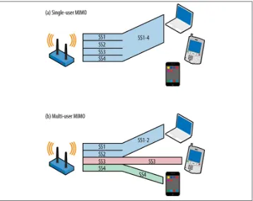
Figure 1-2 compares the single-user MIMO technologies used in 802.11n with the new
multi-user MIMO in 802.11ac. In Figure 1-2(a), all of the spatial streams are directed
to one receiving device. In 2013, multiple spatial streams were a commonplace technical innovation, supported in every 802.11n AP and almost every client device. In contrast,
Figure 1-2(b) shows what it means for a MIMO transmitter to be multi-user. In the figure, the access point is transmitting four simultaneous spatial streams. The magic of MU-MIMO is that the four spatial streams are being transmitted to three separate de‐ vices. Two of the spatial streams are transmitted to a laptop supporting high-speed data transmission. Each of the other two spatial streams is transmitted to a single-stream device, such as a phone or tablet computer. To keep the three transmissions separate, the AP uses beamforming to focus each of the transmissions toward its respective re‐ ceiver. For this type of scenario to work, it is necessary that the receivers are located in different enough directions that focused transmissions avoid interfering with each oth‐ er. Due to the potential of inter-stream interference, multi-user transmissions require
more up-to-date feedback, a challenge that will be discussed more in Chapter 4.
Multi-user MIMO has the potential to change the way Wi-Fi networks are built because
it enables better spatial reuse. One of the keys to building an 802.11 network of any type
is reusing the same channel in multiple places. For example, in Figure 1-3(a), the radio
channel is used for omnidirectional transmissions. When the AP transmits, the radio energy is received by both the laptop and the smartphone, and the channel may be used to communicate with only one of the devices at any point in time. One of the reasons why high-density networks are built on small coverage areas is that the same radio channel can be reused multiple times, and each AP in a dense network can transmit on the channel independently. Multi-user MIMO builds on the small-cell approach by
enabling even more tightly packed networks. In Figure 1-3(b), MU-MIMO is in use. As
Figure 1-2. Single- and multi-user MIMO comparison
4. The issue is actually a little more complicated. Most regulators require restrictions on side band emissions, so even if you have 83 MHz of spectrum, the harmonic lobes above and below the main 80 MHz transmission may be too powerful to meet side band emission requirements. When defining the channel width, 802.11ac has limits on the transmitted power outside the main band at ±120 MHz from the center frequency, and therefore, an 802.11ac channel does not fit in the 2.4 GHz band.
Getting MU-MIMO implementations right, however, is quite complex. The simple
world of Figure 1-3 is an ideal depiction. In practice, there will always be some crosstalk
between transmissions to different clients. As an implementation matter, each of the
multiple transmissions in Figure 1-3(b) will be slower than the single transmission in
Figure 1-3(a), but the total throughput in the multiple-transmission case will be larger.
Operating Frequency Band for 802.11ac
Unlike 802.11n, which operated all across the unlicensed spectrum bands allocated to wireless LANs, 802.11ac is restricted to 5 GHz operation only. 802.11ac’s PAR stated that it would only work at 5 GHz. In effect, this is a recognition that 802.11n is as good as it’s going to get for the 2.4 GHz band, and future technologies are not going to come to the old crowded spectrum there.
802.11ac operates only in the 5 GHz frequency band. It is not avail‐ able in the 2.4 GHz band.
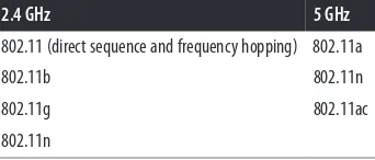
Table 1-2 lists the 802.11 versions that operate in each frequency band.
Table 1-2. 802.11 standards operating in the 2.4 GHz and 5 GHz bands
2.4 GHz 5 GHz
802.11 (direct sequence and frequency hopping) 802.11a
802.11b 802.11n
802.11g 802.11ac
802.11n
The decision to keep the 802.11ac specification from running in the 2.4 GHz band is frequently a source of questions from users who hope that 802.11ac will dramatically improve the performance of older 2.4 GHz devices. Unfortunately, there is sound tech‐ nical justification for why 802.11n is the “end of the line” for the 2.4 GHz spectrum. Making 802.11n the capstone technology for the 2.4 GHz band is based on the relatively small benefit from the major features in 802.11ac. Most notably, one of the major tech‐ niques used to increase speed in 802.11ac is significantly wider channels. Doubling channel width to 40 MHz in 802.11n provided a little more than double the speed. 802.11ac goes even farther, to 80 and 160 MHz channels, but there is not 160 MHz of
5. One reviewer pointed out to me that there have been some microwave ovens that operate around 5 GHz, but thankfully, they were not commercially successful.
If, however, you decide to fully utilize the channel across the whole 80 MHz, by defi‐ nition the entire open frequency band must be free of other transmissions. Using 40 MHz channels in a 2.4 GHz 802.11n network is hard enough because two of the three available transmission channels must be clear in order to transmit. Keeping all three 2.4 GHz channels clear would be even harder. If you can reliably keep all three available channels free, my only advice is to start buying lottery tickets because you clearly have luck with you. Even on a network that is intended only for use with new wide band 802.11ac devices, there will still be other narrowband devices. Too many battery-operated phones and tablets are in use to believe that a network can be restricted only to wide band devices.
The second big protocol feature to boost speed in 802.11ac is the move to the aggressive 256-QAM coding, which requires clean spectrum to have transmissions “land” on the
right constellation point. (Don’t worry, I’ll write more about this in Chapter 2.) Spectrum
at 5 GHz is much cleaner because there isn’t interference from Bluetooth, microwave ovens, 2.4 GHz cordless phones, or any of the many random devices that pollute the 2.4
GHz band.5 Although none of these devices taken alone does much to increase the noise
level, taken together they may collectively raise the noise floor by about 5 dB overall. In some ways, regulation of 5 GHz operation is more protective, and tends to reduce in‐ terference as well. When you are trying to do something so channel quality–sensitive as 256-QAM, even small sources of noise are a major barrier.
802.11ac Product Development Plans
In the early days of 802.11, new physical layer specifications were smaller and came to market in one step. Starting with 802.11n, the technical specifications began to outrun product development capacity, and large specifications now come to the market in dis‐ tinct waves. The first wave of 802.11ac products will be driven by the enthusiasm for higher speeds. APs will typically have three stream capabilities, but with 802.11ac pro‐ viding 80 MHz channels and 256-QAM modulation, the speed will go from 450 Mbps to 1.3 Gbps. The second wave of 802.11ac products will add even wider channels and
possibly even multi-user MIMO support, as outlined in Table 1-3. Later waves will add
Table 1-3. Anticipated 802.11ac technology waves
Attribute First wave Second wave
Maximum number of spatial streams 3 3 or 4
Channel width 80 MHz 160 MHz
Maximum modulation 256-QAM 256-QAM
Typical maximum speed 1.3 Gbps 2.6 Gbps
Beamforming support Varies (depending on vendor) Yes
There’s fifty-seven channels and no free airtime...
—Bruce Springsteen, singing “57 Channels (And Nothin’ On)” as a wireless administrator
CHAPTER 2
The PHY
Large improvements in 802.11 speeds typically have resulted from the introduction of a big new idea. Introducing multi-carrier transmission with OFDM increased speeds in the transition from 802.11b to 802.11a/g. Creating MIMO systems did the same in the move from 802.11a/g to 802.11n. 802.11ac, however, does not introduce a new way of transmitting data over the air. Though they are both extended beyond what was introduced in 802.11n, the techniques used to put bits on the air in 802.11ac will be familiar to anybody familiar with 802.11n: MIMO and wide channels. Raw speed in‐ creases in the PHY come from three sources: a higher number of MIMO streams, wider channels, and a finer modulation that can pack more bits into each unit of airtime.
Extended MIMO Operations
1. As you will see in Chapter 4, this is an (intentionally) simplified description of MIMO transmission. A single data stream does not necessarily follow a single clean, linear path through space, in large part due to the dependence of transmission on frequency.
The number of spatial streams can be no greater than the number of elements in the antenna array. When the count of array elements ex‐ ceeds the number of spatial streams, there is an additional signal pro‐ cessing gain that can be used to improve the signal-to-noise ratio in beamforming.
Beamforming is a capability that was first proposed in 802.11n, though it never achieved widespread implementation. By using the antenna array to send carefully phase-shifted energy patterns, it is possible to “steer” a data stream toward a particular receiver. 802.11ac builds on beamforming by allowing multiple simultaneous transmissions for multi-user MIMO (MU-MIMO). MU-MIMO is one of the key technologies that will take 802.11ac far beyond its published (or “headline”) data rate for frame transmission. Instead of having a single transmitter and receiver in the same area, MU-MIMO enables
spatial reuse, where the same channel can be used in different areas by the same access point. This exciting development will bring the benefits of switching and reduced col‐ lision domains to 802.11 networks. It is a topic that requires its own in-depth exposition because it requires communication between protocol layers; it is discussed fully in
Chapter 4.1
Radio Channels in 802.11ac
To the well-established 20 MHz channel that has been widely used in 802.11 from the first standardization of OFDM in 802.11a and the 40 MHz channel used in 802.11n, the 802.11ac brings two new channel sizes. As expected, wider channels bring higher throughput. Just as in previous OFDM-based transmission, 802.11ac divides the chan‐ nel into OFDM subcarriers, each of which has a bandwidth of 312.5 kHz. Each of the subcarriers is used as an independent transmission, and OFDM distributes the incom‐
ing data bits among the subcarriers. A few subcarriers are reserved and are called pilot
carriers; they do not carry user data and instead are used to measure the channel.
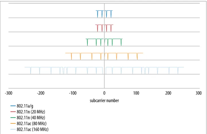
Radio Channel Layout
To increase throughput, 802.11ac introduces two new channel widths. All 802.11ac devices are required to support 80 MHz channels, which doubles the size of the spectral channel over 802.11n. It further adds a 160 MHz channel option for even higher speeds. Due to the limitations of finding contiguous 160 MHz spectrum, the standard allows for a 160 MHz channel to be either a single contiguous block or two noncontiguous 80
and pilot carriers defined in 802.11ac, along with the channel formats from 802.11a/g and 802.11n for comparison. In the figure, each horizontal line represents the layout of OFDM subcarriers in one type of channel, ranging from the 20 MHz channels first used with OFDM up to the widest channel that 802.11ac has to offer. Pilot carriers are rep‐ resented by the dips down in the line to show that they carry no data.
Figure 2-1. Channel layouts in 802.11ac
This section describes the channel layout for a single 802.11ac radio. Most “802.11ac” APs that are sold initially will consist of a single 802.11ac 5 GHz radio plus a second 802.11n radio in the 2.4 GHz band.
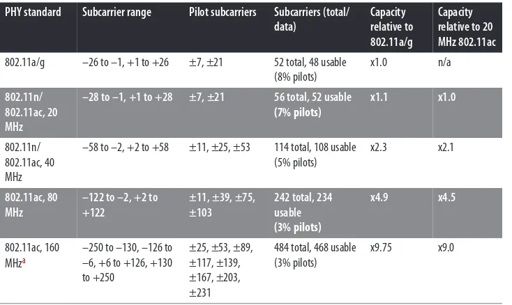
Pilot carriers are a form of overhead used in OFDM, and they represent an overhead for the channel. In MIMO systems, a single pilot carrier can be more effective at assisting with the channel tuning operations. As a result, the pilot overhead in 802.11ac has almost
a “bulk discount” effect with the wider channels. Table 2-1 identifies the OFDM carrier
efficient as the width increases. The final two columns in the table depict the throughput relative to the capacity of two forms of 20 MHz channels in 802.11a/g and 802.11ac.
Table 2-1. Channel description attributes
PHY standard Subcarrier range Pilot subcarriers Subcarriers (total/ data)
a For 80+80 MHz channels, the numbers are identical to the 160 MHz channel numbers.
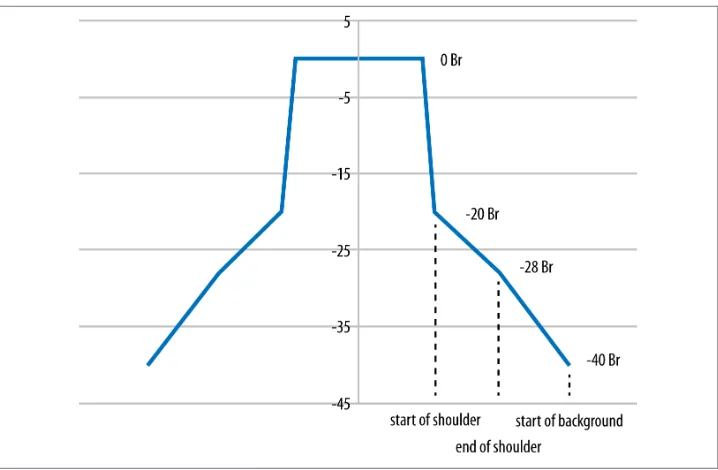
Radio channel spectral mask
802.11ac channels have exactly the same shape as previous OFDM channels, differing
only in the width of the energy transmitted. Figure 2-2 shows the general shape of an
802.11ac channel, which is described as decibels relative (dBr) to the peak level at the channel center frequency. The figure does not label the precise frequencies used because
the spectral mask is the same shape no matter what size channel is used. Table 2-2
describes the key points on the spectral mask: the edge of the high-power peak, the start of the shoulder a few megahertz later, the point at which the shoulder steepens, and, finally, the point at which the background is reached.
Table 2-2. Spectral mask shape
Figure 2-2. Spectral mask
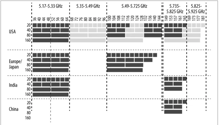
Available Channel Map
Defining the available channels is more of a regulatory question than a technical one. Wireless LAN equipment is built with flexible radio chips that can tune to almost any frequency, and the 802.11 standards have defined a large number of channels. 802.11ac continues to use the same channel numbering defined by its predecessors, as illustrated in Figure 2-3. The top of the diagram identifies the frequency band and the channel numbers within that band. Channel numbers are spaced four digits apart, but within a
wide channel, one of the frequencies is designated as the primary channel; others are
called secondary channels. When used as part of an 80 MHz channel, channel 44 may
be the primary channel, and channels 36, 40, and 48 will all be secondary channels. Generally speaking, when operating, a wireless LAN will send Beacon frames and an‐ nounce its existence on its primary channel, but not on its secondary channels. Primary and secondary channels are important to bandwidth coexistence features, and will be
2. Within the 5.47–5.725 GHz band, wireless LANs are considered “secondary” users, meaning they must avoid interfering with the primary band users. One of the primary band users is Terminal-area Doppler Weather Radar (TDWR) at 5.600–5.650 GHz, a technology that monitors airport approaches for hazardous wind shear conditions. In 1985, Delta Air Lines flight 191 crashed after flying through storms. The crash directly led to onboard wind shear detection and the development of TDWR to assist pilots and air traffic controllers in avoiding these conditions. For more information, see my blog post on why we lost the weather radar channels. Figure 2-3. Available channel map for 802.11ac
As data has moved from existing wired LANs to wireless networks, additional spectrum has been made available. Regulators are generally aware of the need for additional spec‐ trum, especially to make wider channels available for maximum speeds. The 802.11ac specification defines the channel numbering and layout, but the final say on whether a particular chunk of spectrum can be used lies with the national regulator.
Within Figure 2-3, there is a significant fraction of the spectrum depicted that represents
proposed capacity for wireless LANs in the United States. In early 2013, the FCC acted to make a large amount of additional spectrum available. First, it acted to reclaim the
“missing” channels between 120 and 128.2 Second, the FCC moved to allocate two new
3. The Commission action to propose rules for this new spectrum, numbered FCC 13-22, is available at the FCC website.
Proposed Additional Spectrum for 802.11ac in the United States
While this book was being written, the FCC proposed new rules that would dramatically increase the amount of spectrum available in the 5 GHz band. The first draft of the
proposed rules was released on February 20, 2013.3 The proposed rules go a long way
to unifying the FCC rules in the 5 GHz band. Product developers will benefit from simpler rules, especially if the FCC action eventually leads to more consistent rules throughout the world. In the proposed rulemaking, the FCC specifically sought com‐ ment on how to work toward having one set of worldwide rules.
Even though 802.11 started off its life in the 2.4 GHz band that was originally considered to be “junk,” the proposed rules illustrate how far 802.11 has come since it first came to market. Julius Genachowski, the FCC chairman at the time the new rules were proposed, has written and spoken extensively about how unlicensed spectrum fosters innovation, and the proposed rules reflect a broad consensus among the commission that enabling the further development of Wi-Fi is a useful goal.
Transmission: Modulation, Coding, and Guard Interval
Compared to prior 802.11 specifications, 802.11ac makes only evolutionary improve‐ ments to modulation and coding. Compared to its immediate predecessor, 802.11ac simplifies the selection of modulation and coding by discarding the rarely implemented unequal modulation options. Improved modulation technology provides one of the major points where 802.11ac picks up speed. Using the more aggressive 256-QAM modulation lets the link pack in two more bits on each carrier, for a total of eight bits instead of six. Adding two bits increases capacity by a third.
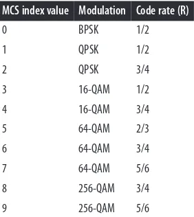
Modulation and Coding Set (MCS)
Selecting a modulation and coding set (MCS) is much simpler in 802.11ac than it was in 802.11n. Rather than the 70-plus options offered by 802.11n, the 802.11ac specifica‐
tion has only 10, shown in Table 2-3. The first seven are mandatory, and most vendors
will support 256-QAM, and therefore all nine MCS options, in all products they bring
to market. Modulation describes how many bits are contained within one transmission
4. There is a bit more to QAM than saying that it uses phase shifts and amplitude levels, but if you want to know the details, you are probably in a hardware engineering class or are a chip designer.
R=1/2 transmits one user data bit (the numerator) for every two bits (the denominator) on the channel. Higher code rates have more data and less redundancy at the cost of not being able to recover from as many errors. In 802.11ac, modulation and coding are coupled together into a single number, the MCS index. Each of the MCS values can lead to a wide range of speeds depending on the channel width, the number of spatial streams, and the guard interval. 802.11ac also does away with unequal modulation, a protocol feature from 802.11n that was not widely implemented.
Table 2-3. MCS values for 802.11ac
MCS index value Modulation Code rate (R)
0 BPSK 1/2
1 QPSK 1/2
2 QPSK 3/4
3 16-QAM 1/2
4 16-QAM 3/4
5 64-QAM 2/3
6 64-QAM 3/4
7 64-QAM 5/6
8 256-QAM 3/4
9 256-QAM 5/6
One of the ways that 802.11ac simplifies the selection of modulation and coding is that the modulation and coding are no longer tied to the channel width, as they were in 802.11n. To determine the link speed, knowledge of the MCS must be combined with the channel width to produce an overall data rate.
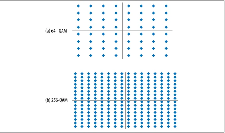
256-QAM modulation
Table 2-3 describes a new modulation for use with 802.11ac. Previous 802.11 standards allowed for up to 64-QAM, which allowed each transmission symbol to take on one of
64 values. At a high level, quadrature amplitude modulation (QAM) works by using the
combination of amplitude level and phase shift to select one of many symbols in the
constellation. To identify each of the 64 values, there are eight levels of inphase (roughly speaking, a phase shift) and eight levels of quadrature (roughly speaking, the amplitude of a wave). Each time a symbol is transmitted, it may take on one of eight phase shifts
and one of eight amplitude levels.4
constellation has 16 phase shifts and 16 amplitude levels. Figure 2-4 compares the 64-QAM constellation to the 256-64-QAM constellation. At first glance, they’re quite similar, though there are many more constellation points in the latter. One analogy that is often helpful is to compare QAM to a game of darts. The transmitter picks a target point and encodes an amplitude and phase shift. This amplitude and phase shift starts off at the ideal constellation point, and the receiver pulls the transmission out of the air and maps it onto what was received. As the constellation points get closer and closer together, the transmitter must be able to throw its darts much more accurately to hit the target point.
Figure 2-4. Comparison of modulations
The large number of extra points in the 256-QAM constellation point has the potential to dramatically improve speed. Instead of transmitting a maximum of six bits on each subcarrier in the channel, a 256-QAM-encoded link transmits eight bits. This single feature alone represents a 33% increase in speed over its nearest equivalent in 802.11n. But nothing comes for free, and the 256-QAM speed boost is no exception. In order to use 256-QAM, the errors in the radio link must be much smaller than before. In a perfect link with ideal transmissions that are received absolutely error-free, the received points line up exactly on the constellation points, and it is easy to understand what should have been transmitted. Real-world radio links are never perfect, though. When a symbol is received, it does not line up exactly on the constellation point. The difference between the ideal constellation point and the point that corresponds to the received symbol exists
in two-dimensional space, and therefore the “miss” is described by an error vector, as
designers are concerned about is the size of the error and not its direction, so it is
common to speak of the length of the error, which is called the error vector magnitude
(EVM).
Figure 2-5. Error vectors
Not surprisingly, transmitting at 256-QAM requires much smaller errors than the less densely packed prior constellations. For example, when the received symbol is in the
middle of several constellation points, such as in Figure 2-5(b), the receiver must choose
one of the points. If it guesses wrong, the entire frame may need to be discarded. Early implementations of 802.11ac have shown that the required receiver performance for 256-QAM is a gain of about 5 dB over the 64-QAM receiver performance. To achieve better performance, there are a variety of techniques that can be applied. Higher-performance error-correcting codes can provide some of the required Higher-performance; 802.11ac includes a low-density parity check (LDPC) code that can provide a gain of 1–2 dB. Selecting better components for the analog frontend on the radio can also help. In addition to any distortions from the ideal point introduced by the radio channel itself, the receiver’s analog section (antenna and amplifier) can also introduce distortion. Minimizing the introduction of errors in the analog section of an 802.11ac interface helps the digital section do its job better. Using LDPC and improving the analog frontend are not mutually exclusive, and some vendors will do both.
Guard Interval
5. For more information on the short guard interval, see Chapter 3 of 802.11n: A Survival Guide. 6. For more information on error-correcting codes, see Chapter 3 of 802.11n: A Survival Guide.
7. For more information about the HT frame formats in 802.11n, see Chapter 3 of 802.11n: A Survival Guide.
the short guard interval is optional, I expect it to be widely supported, just as it was with 802.11n.5
Error-Correcting Codes
802.11ac does not make any changes to the supported error-correcting codes. Convo‐ lutional codes are required by 802.11ac, as they have been required for all OFDM PHYs. LDPC coding is supported as an option, and typically offers a gain of 1–2 dB over convolutional coding. Therefore, it is likely to be supported in combination with the very high data rates supported by 256-QAM and long packets transmitted in aggregate frames. By enabling higher data rates, LDPC will also assist in increasing the data rates. An increase in the data rate may enable a reduction in the transmission time, and hence
an overall power savings.6
PHY-Level Framing
When designing the physical layer framing for 802.11ac, the protocol designers began by laying out requirements that the new frame needed to meet. Most importantly, it needed to be compatible with previous 802.11 PHYs. When an 802.11ac device trans‐ mits, 802.11a and 802.11n devices must be able to see and avoid the transmission for the length of time required on the medium. To meet this requirement, the format of the VHT physical layer frame is similar to the mixed-mode format used in 802.11n, and it begins with the same fields as 802.11a frames. A second subtle difference is required to enable multi-user MIMO transmissions, which is that the preamble must be able to describe the number of spatial streams and enable multiple receivers to set up to receive their frames. To meet this second requirement, a new physical layer header was required because the 802.11n HT-SIG header field was not readily extensible to new channel widths or large numbers of spatial streams.
Compared to 802.11n, the physical layer for 802.11ac is much simpler because there is
only one format. Figure 2-6 shows the original non-HT format of an OFDM frame in
Figure 2-6(a), along with the 802.11n mixed-mode frame format in Figure 2-6(b) and
Figure 2-6. VHT physical layer frame format
The fields in the VHT frame are as follows:
Non-HT Short Training Field (L-STF) and Non-HT Long Training Field (L-LTF)
These fields are identical to the fields used in 802.11a; they consist of a sequence of 12 OFDM symbols that are used to assist the receiver in identifying that an 802.11 frame is about to start, synchronizing timers, and selecting an antenna. Any 802.11 device that is capable of OFDM operation can decode these fields.
Non-HT Signal Field (L-SIG)
The Signal field is used by 802.11a to describe the data rate and length (in bytes) of the frame, which is used by receivers to calculate the time duration of the frame’s transmission. 802.11ac devices set the data rate to 6 Mbps and derive a spoofed length in bytes so that when any receiver calculates its length, it matches the time duration required for the 802.11ac frame.
VHT Signal A (VHT-SIG-A) and Signal B (VHT-SIG-B) Fields
The VHT Signal fields are the analog of the Signal field used in 802.11a or the HT Signal field used in 802.11n; however, they are understood only by 802.11ac devices. VHT signaling is split into two fields, the Signal A field and its companion, the Signal B field. Taken together, the two fields describe the included frame attributes such as the channel width, modulation and coding, and whether the frame is a single- or multi-user frame. Due to their complexity, these fields are described fur‐
VHT Short Training Field (VHT-STF)
The VHT STF serves the same purpose as the non-HT STF. Just as the first training fields help a receiver tune in the signal, the VHT-STF assists the receiver in detecting a repeating pattern and setting receiver gain.
VHT Long Training Field (VHT-LTF)
The VHT long training field consists of a sequence of symbols that set up demod‐ ulation of the rest of the frame, starting with the VHT Signal B field. Depending on the number of transmitted streams, it consists of 1, 2, 4, 6, or 8 symbols; the number of required symbols is rounded up to the next highest value, so a link with five streams would require six symbols. This field’s contents are also used for the channel estimation process that beamforming depends on.
Data field
The Data field holds the higher-layer protocol packet, or possibly an aggregate
frame containing multiple higher-layer packets. This field is described in “The Data
Field” on page 28. If no Data field is present in the physical layer payload, it is called a null data packet (NDP), which is used by the VHT PHY for beamforming setup, measurement, and tuning.
Null data packets are physical layer packets, not MAC layer packets. When a physical layer packet has no embedded payload, there is noth‐ ing for a MAC analyzer to report.
The VHT Signal Fields
All of the multi-carrier 802.11 PHYs use a Signal field to describe the payload of the physical layer frame, and 802.11ac is no exception. The purpose of the Signal field is to help the receiver decode the data payload, which is done by describing the parameters used for transmission. 802.11ac separates the signal into two different parts, called the Signal A and Signal B fields. The former is in the part of the physical layer header that is received identically by all receivers; the latter is in the part of the physical layer header that is different for each multi-user receiver.
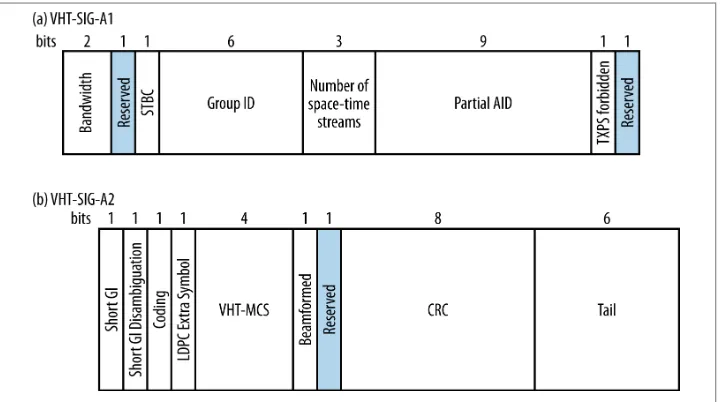
VHT Signal A field
The Signal A field comes first in the frame, and it may take on one of two forms de‐ pending on whether the transmission is single-user or multi-user. The depiction of the
Signal A field in Figure 2-7 is the format for a single user. (The multi-user format will
be discussed in Chapter 4.) Because it holds rate information for decoding the payload
8. STBC may be used when the number of radio chains exceeds the number of spatial streams; it transmits a single data stream across two spatial streams. In effect, it takes MIMO gain and translates it into increased range.
symbol, are referred to as VHT-SIG-A1 and VHT-SIG-A2. The two halves of the field
are shown as Figure 2-7(a) and Figure 2-7(b), respectively. To assist a receiver in rec‐
ognizing that the header belongs to a VHT frame, the constellation rotates between the two symbols.
Figure 2-7. VHT Signal A field (single-user format)
The components of the Signal A field are:
Bandwidth (2 bits)
Two bits are used to indicate the channel bandwidth: 0 for 20 MHz, 1 for 40 MHz, 2 for 80 MHz, and 3 for 160 MHz.
STBC (1 bit)
If the payload is encoded with space-time block coding (STBC)8 for extra robust‐
ness, this field will be 1. Otherwise, it will be 0.
Group ID (6 bits)
Number of space-time streams (3 bits)
This field indicates the number of space-time streams, but the field is zero-based. Therefore, the number of space-time streams will be one greater than the binary value of this field. For example, if the field is the number 3, then there are four space-time streams.
Partial AID (9 bits)
For transmissions to an AP, the partial AID is the last nine bits of the BSSID. For a client, the partial AID is an identifier that combines the association ID and the BSSID of its serving AP.
Transmit power save forbidden (1 bit)
If the access point in a network allows client devices to power off radios when they have the opportunity to transmit frames, this field will be 0. Otherwise, it is 1.
Short GI (1 bit)
This field is set to 1 to indicate that the 400 ns short guard interval is used for the data payload of the physical layer frame. Otherwise, it is 0.
Short GI disambiguation (1 bit)
When the short guard interval is used, an extra symbol might be needed for the payload of the physical layer frame. A single bit is used to indicate whether the extra symbol is required (1) or not (0).
Coding (1 bit)
This field is 0 when convolutional coding is used to protect the Data field, and 1 when LDPC is used.
LDPC extra symbol (1 bit)
LDPC coding can create the need for an extra OFDM symbol to transmit the Data field. If this field is set to 1, it indicates the extra symbol is required.
MCS (4 bits)
This field contains the MCS index value for the payload, as shown in the first column of Table 2-3.
Beamformed (1 bit)
When a beamforming matrix is applied to the transmission, this bit is set to 1; otherwise, it is set to 0.
CRC (8 bits)
Tail (6 bits)
Six zeros are included to terminate the convolutional coder that protects the Signal A field. Convolutional codes require a “ramp down” of trailing zeros to function properly.
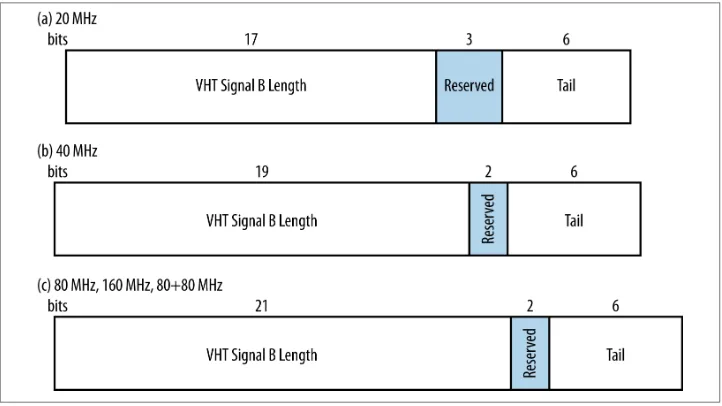
VHT Signal B field
The VHT Signal B field is used to set up the data rate, as well as tune in MIMO reception. Like the VHT Signal A field, it is modulated conservatively to assist receivers in deter‐ mining the data rate of the payload; however, it is modulated using the VHT MCS 0. Although it is modulated with BPSK with a convolutional code of R=1/2, the VHT modulations have slightly more efficiency and hold a few more bits. The VHT Signal B field is designed to be transmitted in a single OFDM symbol, which is why it has slightly
different lengths depending on the channel width. Figure 2-8 shows the single-user
format of the VHT Signal B field and its dependence on channel width. (Other formats for this field will be discussed in Chapter 4.)
Figure 2-8. VHT Signal B field (single-user format)
In its single-user form, the raw VHT Signal B field is either 26, 27, or 29 bits, depending on the channel width, and consists of the following fields:
VHT Signal B Length (17, 19, or 21 bits)
field). The reason why this field measures not the actual number of bytes but the
number of four-byte chunks is for efficiency, as will be explained in “Frame Size
and Aggregation” on page 38.
Reserved bits (2 or 3 bits)
The bits between the length field and the tail are reserved, and must be set to 1.
Tail bits (6 bits)
Six zero bits are included to allow the convolutional coder to complete.
There is no CRC within the VHT Signal B field. To detect errors in the VHT Signal B field, there is a CRC at the start of the Data field, which will be described in the next section.
To transmit the VHT Signal B field, it is expanded to fill the available space within one symbol. Wider channels have the capacity to carry more data, so the Signal B field is
repeated, as shown in Figure 2-9. For a 40 MHz channel, the field is repeated once. For
an 80 MHz channel, the field is repeated three times and a pad bit of 0 is appended. For a 160 MHz (or an 80+80 MHz) channel, the field is repeated four times, a pad bit of 0 is added, and then the resulting structure is repeated once. This process of repeating the signal field ensures that it occupies exactly one symbol.
The Data Field
Immediately following the physical layer header, the Data field begins to transmit the payload of the physical layer frame. The format of the Data field is shown in
Figure 2-10. Because the Data field is transmitted following the header, it is transmitted at the data rate described by the physical layer header. The Data field carries a frame from higher protocol layers.
Figure 2-10. Physical layer data encoding
Before beginning transmission of the data from higher-layer protocols, there are a few housekeeping fields embedded in the physical layer frame:
Service (16 bits)
The Service field is prepended to the higher-level protocol data before transmission. It consists of seven bits to initialize a data scrambler to avoid long runs of identical bits and a CRC of the VHT Signal B field to detect errors.
PHY Service Data Unit (PSDU), or frame from MAC layer
The PSDU field contains a frame from from the 802.11 MAC layer. It is variable length.
PHY pad
To ensure that the number of bits passed to the transmitter will exactly match the number of bits required for a symbol, pad bits are added.
Tail
9. For more information on puncturing, see Chapter 13 of 802.11 Wireless Networks: The Definitive Guide.
The Transmission and Reception Process
A block diagram for an 802.11ac interface is shown in Figure 2-11. This block diagram
can be used to transmit both single-user and multi-user frames, but this chapter focuses on the single-user transmission use case.
Figure 2-11. 802.11ac block diagram (single-user only)
When the MAC presents a frame for transmission, it is passed to the physical layer, and the following procedure is run:
1. Preparation of Service field. To begin, the Service field that is prepended to the data for transmission is constructed. The main component of the Service field is the CRC calculated over the contents of the VHT-SIG-B field.
2. PHY padding. The first step in transmission is to pad the frame so that its length matches the number of bits required to end on a physical-level symbol boundary. 3. Scrambling and forward error correction (FEC) encoding. The scrambler reduces
the probability of long strings of identical bits in its output, and is present because convolutional codes work best on data that does not have long runs of identical bits. The output of the scrambler is fed to a FEC encoder, which may be either a con‐ volutional coder or an LDPC encoder. To achieve many different code rates, a