Performance Analysis of Scheduling Schemes for Femto to
Macro Interference Coordination in LTE-Femtocell
Deployment Scenario
Rafina Destiarti Ainul, Hani’ah Mahmudah, Ari Wijayanti
Telecommunication Engineering Politeknik Elektronika Negeri Surabaya Jalan Raya ITS, Sukolilo 60111, Indonesia
E‐mail: [email protected], {haniah,ariw}@pens.ac.id
Abstract
Deploying femtocells that have low power level in LTE with small coverage area is an alternative solution for mobile operators to improve indoors network coverage area as well as system capacity. However deploying femtocells (HeNB) that were used co‐channel frequency, can be brought about interference problem to the Macro BTS (eNB). Close Subscriber Group (CSG) of HeNB allows only User equipment (UE) to access HeNB. HeNB is the source of interference for UE who cannot access it. Therefore it is necessary for interference coordination methods among the HeNB and eNB. The methods are ICIC (Intercell Interference Coordination) and eICIC (enhanced Intercell Interference Coordination). This paper proposed performance analysis of scheduling schemes for Femto to macro interference coordination that allocated resource in the frequency and time domain using LTE‐Femtocell suburban and urban deployment scenario. Simulation result using ICIC methods can improve SINR performance 15.77 % in urban and 28.66 % in suburban, throughput performance 10.11 % in urban and 21.05 % in suburban. eICIC methods can improve SINR performance 17.44 % in urban and 31.14 % in suburban, throughput performance 19.83% in urban and 44.39 % in suburban.The result prove using eICIC method in time domain resource have better performance than using ICIC method in frequency resource. However using eICIC method in suburban deployment scenariocan increase the performance of SINR and throughput more effective than using eICIC method in urban deployment scenario.
Keywords: HeNB, eNB, UE, ICIC, eICIC.
1. INTRODUCTION
LTE allows for using the heterogeneous network as cells which have a low power level. Using low power level nodes can improve locally the capacity and coverage. Femtocells, known as ‘home evolved node base station (HeNB)’, are low‐power, low‐cost cellular network access points that connect standard mobile devices to a mobile operator’s network using residential DSL, cable broadband connections, optical fibers or wireless last‐mile technologies [1]. LTE has set specifications for femtocells installation and their coexistence with macrocell infrastructure. Using femtocell in LTE with a smaller coverage area 10‐30 m is considered have a more effective performance than envolved node base station (eNB). This is because the capacity for users who can access the femtocell is very limited, so the possibility of traffic congestion in femtocells is smaller than using eNB.
Recently, HeNB deployment can be classified mainly in two scenarios i) urban and ii) suburban deployment model [1]. The dense urban models are useful to model environments with many femtocells. Urban deployment model is using apartment environment, that described urban condition. However, in the suburban environment these models would be exaggerated as a density of femtocellwhich is less. Suburban deployment model for femtocellsis using path loss model in the suburban residential environment for HeNBto the user equipment (UE).
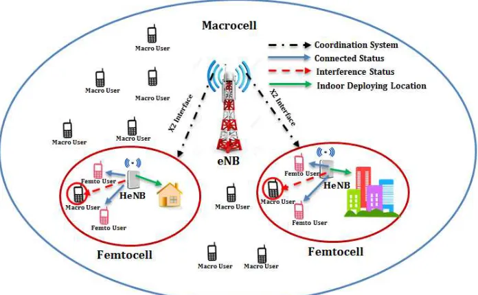
Despite its advantages, femtocells may also lead to significant local service degradation due to interference issues. Sharing the same available bandwidth with the Macrocell network may lead to severe interference phenomenon when there is co‐channel operation, between femto to macro (also known as cross‐tier interference), and between femto to femto.Femtocells have system access that is close subscriber group (CSG). CSG system access allow only UE that can connect to the HeNB. eNB and HeNB that used same frequency spectrum will get co‐channel interference phenomena. The other UE that can’t connect to the HeNB will get interference signal from the HeNB.This condition is called femto to macro interference. Femto or HeNB is the source of interference for UE or macro UE that can’t access it. Therefore, to implement femtocell to the LTE is needed coordination method among the HeNB with the nearest eNB. Inter‐Cell Interference‐Coordination (ICIC) and its evolution eICIC (enhanced ICIC), compose several techniques aiming to reduce interference harmful affects, operating at medium time scale [2‐3].
Figure 1. Femto to Macro Interference
ICIC method works in frequency domain resource allocation that uses dynamic priority which is performed based on user priority. The proposed priority scheme determines the priority of each UE using interference level, Quality of Service and Head of Line. UEs could be scheduled based on their priority on the specified sub‐bands [5]. Consequently, it could improve the system performance in terms of cell throughput and cell edge throughput [3‐ 11].
One Significant concept introduced by eICIC is Almost Blank Subframe (ABS) that using time domain resource allocation [2‐4] [6‐11]. In ABS there is no transmission data among receiver and transmitter [2‐4] [6‐11]. It can be allocated to the user that got interference, so ABS can decrease the interference affect among victim MUEs (macro user equipment) and femtocell. The performance evaluation of the scheme shows that the performance of the macro‐cell is significantly improved but with the expense of degrading the performance of the femtocells triggered to operate in ABS mode [4][7].
Scheduling is simply allocating or reserving resources to users in a communication system to maximize throughput and system efficiency. Scheduling in LTE downlink takes advantage of various factors including channel variations by allocating frequency and time resources to UE with transiently better channel conditions [6].
priority was the main point to get the resource allocation. Based on the user priority was not all UE in this system to get resource allocation directly and needed scheduling system. It was different between previous research [2‐3] [7‐9] [11] in conventional resource allocation that was not used scheduling schemes. In conventional resource allocation was not increased the performance effectively, because there are some UEs that were had low performance was caused by interference effect from the other cell (pico, femto). Using the user priority in scheduling schemes, UE with the low performance get the highest priority to allocate resource [12].
Due to the lack of the previous researchers, in this paper,we further extend the scheduling schemes of resource allocation that we proposed before in [12]. The contribution of this paper is to propose another deployment scenario that was used in LTE‐femtocell. Urban and suburban deployment scenario have difference performance in coordination method. Suburban deployment scenario has better performance than urban deployment scenario. The position of femto or HeNB in suburban deployment scenario is apart from the other so macro UE that was deployed, get less interference affect from HeNB. This condition was different when it deployed in urban scenario. From the performance result, this proposed method was compatible to implement in real condition of LTE (4G cellular technology). Based on 3GPP LTE standardizations, LTE has average user throughput 5 – 12 Mbps in downlink and 2 – 5 Mbps in uplink [13]. It also proves from link LTE link budget system which shows the interference margin and minimum SINR requirement of LTE. In uplink link budget system, the interference margin is 1 dB that is required minimum SINR ‐7 dB, while in downlink system the interference margin is 4 dB and the minimum SINR is ‐9 dB [14]. The result of proposed method have throughput performance range 1.83 – 9.47 Mbps in suburban and 1.42 – 3.47 Mbps in urban deployment scenario for HetNet especially LTE‐Femtocell. Furthermore, the result of proposed method shows based on the SINR cumulative probability function (CDF), in 0.9 CDF the value of SINR larger than 1 dB at urban and suburban deployment scenario. According the result, this proposed system appropriate to apply in the existing LTE cellular system based on the planning system and performance result.
The rest of paper is organized as follows: conventional related work is explained in section II, section III shows the proposed scheme in femto to macro coordination method based on resource allocation, section IV shows simulation algorithm to implement coordination method in LTE‐Femtocell deployment scenario, and section V shows performance analysis of the proposed scheme through simulation. Finally, we conclude the results in section VI.
2. RELATED WORKS
consisting of small cells, such as a low‐cost, low‐power over macrocell, is called heterogeneous network. Picocells are low‐power operator‐installed cell towers, with the same backhaul and access features as macrocells. Interference occurs among network element that belongs to different tiers of the network for the example cross‐tier interference among picocell and macrocell. Resource allocation process is done by Soft Frequency Reuse (SFR) and almost blank subframe to manage interference in frequency and time domain[3]. It needs proposes scheduling and positioning strategies for UE that was got interference. Using proposed schedulingin resource allocation achieves a good balance capacity and fairness [12].
Another intercell interference problem in heterogeneous network was femtocell to macrocell interference. Hence, femtocell will potentially be the source of strong and unpredictable interference. Almost‐blank subframe (ABSF) is a time domain technique to mitigate interference in heterogeneous environment[4]. A join resource block and transmit power allocation scheme in LTE also can decrease inter cell interference. In a join resource block, the users in each cell are scheduled on the specified subbands based on their priority[5].
LTE‐Femtocell needs deployement model in order to evaluate path loss for every HeNB, eNB and calculate HeNB and eNB capacity based on path loss. SINR and throughput performance calculated from the received power which is then used to estimate the overall capacity of femtocell. Suburban deployment model in residential environment proved that the problem of less coverage within a household is solved. The minimum UE capacity that connected to the HeNB is 3 Mbps [1]. Urban was the other deployment scenario that was used to LTE‐Femtocell deployment[16]. Using urban deployment scenario in intercell interference coordination method for femto to macro can be increasing throughput and SINR performance [7]. Using almost blank subframe allocation in urban deployment scenario can be decreasing interference level of UE that can’t access HeNB [3‐4][6‐12]. From urban and suburban deployment model of LTE‐Femtocell, can be used to calculate the performance of UE when using interference coordination method.In this paper, we propose a new approach which is combining scheduling schemes based on UE priority to implement femto to macro interference coordination in time and frequency resource allocation. We extend from our previous network [12] to compare the performance based on deployment scenario and the number of UE in the system.
3. ORIGINALITY
coordination method to mitigate interference. Time resource allocation utilized ABS (almost blank subframe) condition of HeNB. There is no data transmission in ABS condition that can be used to allocate UE that got interference from HeNB.
Resource allocation process needed scheduling schemes to each UE. Scheduling schemes start from the highest priority UE. The highest priority UE will get from the highest performance of SINR and throughput. The value of SINR and throughput performance was obtained from received power level and interference power level. Deployment scenario of LTE‐femtocell will be affected by the received power and interference power. There are two deployment scenarios that were used in this paper, urban deployment based on apartment environment and suburban deployment based on residential environment. Each deployment scenario has different path loss model for eNB, HeNB.
In this paper, we propose a new approach for coordination method for femto to macro mitigation using scheduling system based on user priority which has better performance than conventional resource allocation. The proposed schemes configuremore efficient cellular environment based on LTE, due to the improvement of performance. Also, this improves the overall cell performance in HetNet scenario especially LTE‐Femtocell, for the next generation wireless communication environment.We compare the deployment scenario of urban and suburban, to get the best deployment scenario that was compatible with coordination method. The number of UE in this coordination method can be affected to the performance. Many UEs that were deployed in this system will make the queue in resource allocation process.
4. SYSTEM DESIGN
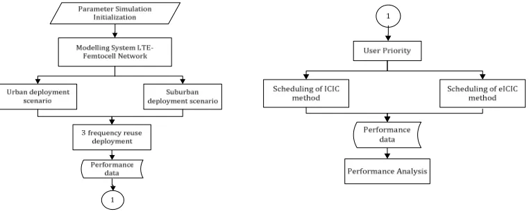
The Proposed system consist of 3 phases : (1) Modeling system using urban and suburban LTE‐Femtocell deployment scenario, (2)Scheduling algorithm to implement ICIC and eICIC method in resource allocation process and (3) Calculate UE performance. The general Diagram System is shown in Figure 2.
4.1 Modeling System of LTE-Femtocell Network
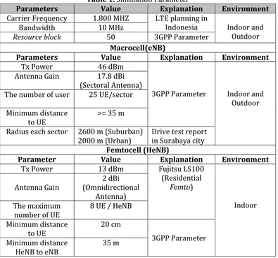
In this simulation will be modeling of system using heterogeneous network as a low power level node HeNB to the macrocell network eNB.eNB network layout design will be described in hexagonal cells that have three sectors. While the layout design of HeNB cell will be described in a circle with the position is inside the room at random. This research will be conducted two modeling system based on existing environmental conditions, namely suburban and urban deployment scenario. There are three kinds of UE in this system. Those are macro UEindoor, macro UE outdoor and femtoUE. Macro UE indoor and femtoUE are dropped uniformly in the same location of femtocell (HeNB). MacroUE outdoor are dropped at the outdoor location. The numbers of macro UE outdoor, macro UE indoor and femtoUE are seven, ten, and eight users each sector. The relevantguidelinesof the simulation are listed in Table 1.which is for macrocell and femtocell respectively.
Table 1. Simulation Parameter
Parameters Value Explanation Environment
Carrier Frequency 1.800 MHZ LTE planning in
Indonesia Indoor and Outdoor
Bandwidth 10 MHz
Resource block 50 3GPP Parameter
Macrocell(eNB)
Parameters Value Explanation Environment
Tx Power 46 dBm
3GPP Parameter Indoor and Outdoor Antenna Gain 17.8 dBi
(Sectoral Antenna) The number of user 25 UE/sector
Minimum distance to UE
>= 35 m
Radius each sector 2600 m (Suburban) 2000 m (Urban)
Drive test report in Surabaya city Femtocell (HeNB)
Parameter Value Explanation Environment
4.1.1 Suburban Deployment Scenario
In the sub‐urban deployment based on author present in [1], was assumes residential neighborhood model that has an area of 30 x 60 m (Fig. 3). The model consists of the dual stripe of houses with roads in between the two stripes. The road is assumed to have a width of 10m and divides the stripes symmetrically. The model further describes two types of residential houses with each house assumed to have one floor. Type‐I houses are of Length 10m and Width 10m (10m×10m) and type‐II houses are of Length 20m and Width 10m (20m×10m) [1].
Figure 3. LTE Femtocell suburban deployment scenario
LTE femtocell propagation models are vital in the calculation of path loss from HeNB to the UE and eNB to the UE. The system developed is based on the HeNB to UE path loss models from 3GPP standardizations. The path loss between femto UE located inside the building and a HeNB in line of sight (LOS) and non‐line of sight (NLOS) condition is calculated as[15]:
(1)
(2)
(q) that was separated between HeNB and femto UE. The simulation result based on suburban deployment model using Matlab was depicted in Figure 4.
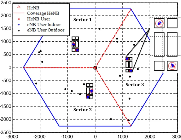
Based on simulation result, the position of eNB is at the center of the cell or at point (0.0) which have three sector coverage. Each sector was generated a residential neighborhood that consists of several houses in it. The house size 10 x10 m was scaled 1:10 into 100 X 100 m while the size of 10 x 20 m house will be enlarged using 1:10 scale and 1:20 into 100 x 200 m.HeNB position will be located in each house that was followed by macro UE indoor and femto UE in random position. Macro UE outdoor was located in the outdoor location in each sector.
Figure 4. Simulation result of suburban deployment scenario
4.1.2 Urban Deployment Scenario
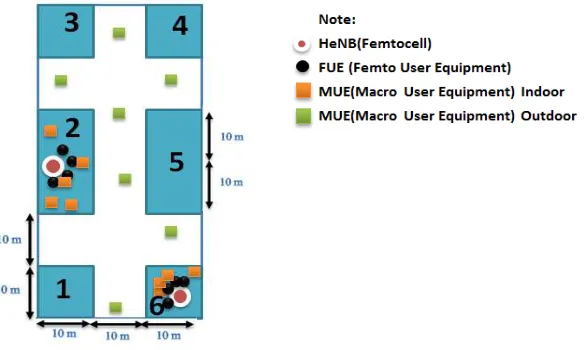
In urban deployment scenario will be modeled an apartment with size 100 x 20 m, which has several rooms with a size 10 x 10 m based on 3GPP standardization in [15]. The depiction of urban environment in Figure 5 only separated by the wall fom one room to another room. Each sector of eNB surrounded an apartment with HeNB inside of the room.
Figure 5. LTE Femtocell urban deployment scenario
-3000 -2000 -1000 0 1000 2000 3000
-2500 -2000 -1500 -1000 -500 0 500 1000 1500 2000 2500
Pemodelan 19 Sel Heksagonal
Satuan jarak dalam meter Sector 1
Sector 2
Path loss model of urban scenario for femto UE to HeNB in LOS condition was calculated in equation (1). However, path loss equation of femto UE to HeNB which in different room (NLOS condition) was calculated as [15] :
(3)
Based on equation (3), the penetration loss of urban environment is 10 dB [16]. The number of walls (q) included to the penetration loss value. In the urban scenario, the value of path loss can be affected by the number of the floor that was deployed (n). In this simulation the apartment has two floors that each floor has the same size of room.
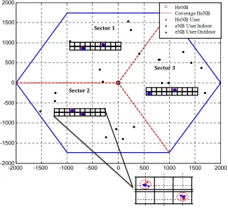
Figure 6. Simulation result of urban deployment scenario
The simulation result of urban deployment scenario was illustrated in Figure 6. The position of eNB located in the center of cell point (0.0), with radius each sector was 2000 m. In each sector, was deployed apartment building that was illustrated urban scenario with 10 rooms in size 10 x 10 m. In simulation process, the rooms were scaled using 1:10 into 100 x 100 m.
From the simulation result in urban and suburban deployment scenario, can be implemented in a real scenario but it depend on 3GPP assumption and standardization in [15]. When this simulation will be used in
-2000 -1500 -1000 -500 0 500 1000 1500 2000
-2000 -1500 -1000 -500 0 500 1000 1500 2000
Sector 2
Sector 1
a general scenario of urban and suburban, it need change the propagation model scenario that was compatible with it.
4.1.3 Frequency Reuse Deployment
The frequency reuse deployment aims to reduce the influence of co‐ channel interference between eNB to eNB. The adjacent eNB used different subcarrier frequency. Co‐channel interference will be separated by reuse distance that can reduced interference power between eNB to eNB. This research will be modeled 19 hexagonal cells with 3 frequency reuse deployment. The equation that was used to calculate the reuse distance is as follows[17]:
(4)
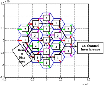
Based on equation (4), D is the reuse distance, R is radius of each environment, and k is coefficient of frequency reuse. Therefore, when applied 3 in coefficient of frequency reuse, the nearest co‐channel spacing in the sub‐ urban environment is 7800 m, while in the urban environment is 6000 m. The modeling system using 3 frequency reuses was illustrated in Figure 7, that was from simulation result 19 hexagonal cells in suburban deployment scenario.
Figure 6. 3 Frequency reuses deployment in 19 hexagonal cells
There are 3 adjacent cells which use the different channel in frequency reuse. It was marked with the number 1, 2 and 3 in Figure 6. The
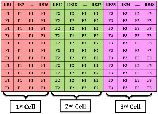
co‐channel interference was characterized by using the same number in each cell. From the result of modeling system 19 hexagonal cells, it has 6 co‐ channel interferences. Using same and different channel was based on the resource block allocation. A resource block is a set of subcarriers that are arranged into a block‐block.The transmission system that was used in LTE was OFDM system. In OFDM system has multi‐carrier concept. The concept of multi‐carrier is related to the principle of resource block itself that was composed of a subcarrier set. The resource block allocation system process in 3 frequency reuseswas illustrated in Figure 7.
Figure 7. Resource block allocation in 3 frequency reuses
Based on resource block allocation in 3 frequency reuses between 1st,
2nd, and3rd Cell used different subcarrier frequency. 1st cell used F1 subcarrier
frequency, 2nd cellused F2, and 3rd cell used F3. The number of subcarrier for
each cell was determined by the bandwidth that was used in the system. This system uses 10 MHz and the number of resource blocks are 50 RB. When 3 frequency reuses deploy in this system, each cell have 3 MHz bandwidth and the number of resourse block are 16 RB. There are 2 resource blocks that weren’t used. The maximum value of subcarrier in each resource block are 12 subcarriers that were used 15 KHz space in each subcarrier, so the maximum bandwidth for each resource block is 180 KHz [14].
Interference factor can also be caused by HeNB deployment. Close subscriber group (CSG) access system of HeNB can be made macro UE that couldn’t access it will be got interference from HeNB. The interference source for each UE will be different. Interference power of each UE based on the interference source was calculated by equation [18]:
(5)
(6)
Based on equation (5) equation (6), is interference power level of femto UE and is interference power level of macro UE. interference level can be calculated from received power level of co‐channel eNB ( and from received power level of the other HeNB in each sector ( .
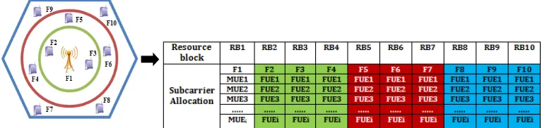
4.2 Frequency Resource Allocation in ICIC Method
Inter cell Interference coordination (ICIC) is a coordination method that using frequency resource allocation to decrease interference problem. The main idea of ICIC method isdivided each cell into two parts, the cell center and cell edge. The center of a macrocell base stations consists of multiple cell edge or cell‐level low power such as femtocells.In the ICIC method, eNB and HeNB will be allocated to different resource block. Resource block allocation sequence begins with the allocation of eNB (RB1) then followed by allocating some of the HeNBs (RB2, RB3, RB4, ...., RBi) as
depicted in Fig. 8. The allocation of HeNB will be rankedover the shortest distance to the eNB, the nearest HeNB to eNB will get the highest priority [5].
Figure 8. Resource block allocation for each cell in ICIC method
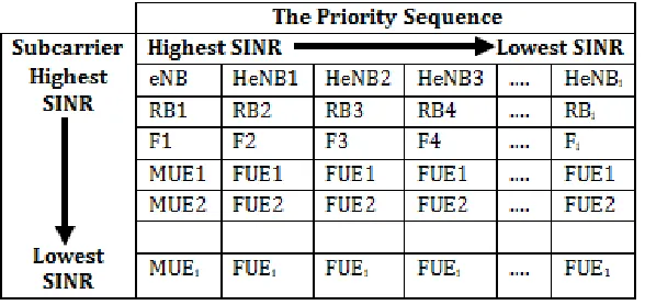
The number of resource block that can be used in ICIC method was 16 RBs. It is based on the concept of 3 frequency reuses that have been deployed before. The number of HeNB that was deployed in each macrocell was allocated in the different resource block. Each UE of HeNB and eNB was allocated in different subcarrier (F1, F2, F3, ....,Fi) which needed scheduling
channel frequency between femto to macro. This process in LTE system was done by X2 interface. X2 interfaces send a message to the interference source of each UE for minimizing the interference level by given minimum access to the interference source.
Figure 9. The priority sequence of UE in scheduling process
After implementing the frequency resource allocation using ICIC method, the SINR performances for each UE can be expressed by equation (7) [7]:
(7)
is received power level from every user that is femto UE or macro UE. While is interference power level of femto UE and macro UE from the other transmitters that used same sub‐band frequency. Then N is the value of thermal noise in this system. Throughput performance in this system can be expressed by equation (8) [7]:
(8)
B is the number of bandwidth on each resource block (180 KHz). The amount of B will be multiplied with the subcarriers number of each resource block [3]. The following execution steps of the proposed algorithm in ICIC method can be described in Algorithm 1:
Algorithm 1 1: Define
RB : Resource Block RB=16; SC : Subcarrier SC = 12; F = (RB, SC);
2:Sort SINR MUE, FUE ascending 3: FOR i=1 to RB
5:Max SINR MUEk = [MUERB][MUESC];
6: IF SINR MUEk< ‐9 dB
7: apply minimum Pr MUEk from HeNB = ‐85 dBm
8: apply Eq.(6)
9:Max SINR FUEk = [FUERB‐i][FUESC‐j];
10: Obtain the number of SC each RB in MUEk& FUEk
11:Apply Eq.(7) 12: Apply Eq.(8) 13. END FOR i,j
4.3 Time Resource Allocation in eICIC Method
In Time resource allocation applied at eICIC (enhanced Inter Cell Interference Coordination) method that is used ABS condition or Almost Blank Subframe that owned by HeNB. The number of ABS are 8 subframes that were based on the maximum number offemto UE. The number of femto UE which was connected to the HeNB, was determined from reselection process. When the received power level of femto UE from the HeNB < ‐85 dBm (threshold), femto UE will be connected to the HeNB [2].The number of ABS was obtained from the number of femto UE that was connected to the HeNB. When there are 6 femto UEs that was connected to the HeNB, it will be 2 ABS of HeNB, as depicted in Fig 10. HeNB uses ABS, which doesn’t transmit signal during some subframe for victim macro UE temporary. Therefore, eNB can avoid interference, by transmitting a signal during the ABS of the femtocell [4].
Figure 10. ABS condition of eICIC method
Figure 11. Information exchange among eNB and HeNB using X2 interface
Scheduling allocation of ABS to the macro UE based on priority level. The priority level is determined based on SINR performance that was the reverse condition from ICIC method. The lowest value of SINR that owned by macro UE will be given a higher priority level to allocate ABS, as illustrated in Fig. 12 [8]. It is because the vital condition improved the lowest performance of macro UE.
Figure 11.Scheduling process of user priority in eICIC method
There are two conditions at eICIC method, ABS condition and non‐ABS condition. During ABS condition all interfering from HeNB remain silent and so the only interference is from the interfering eNB ( ). However, during non‐ABS subframes, there is interference from all interfering HeNBs ( ) and eNBs ( ) both. SINR performance in ABS condition and non‐ABS condition can be modeled by equation (9) (10) [9]:
(9)
(10)
ABS allocation of eICIC method to the macro user that got interference by femtocell is using time domain. Then to calculate SINR performance in function of time, can be expressed by equation (11) [10] :
(11)
ABS Information
HeNB eNB
eNB indentify macro UE that was got interference
eNB using ABS pattern for macro UE that was got interference HeNB
1
2
3
4
5
Request ABS
Where is an indicator function, which is represented as (12) [10]:
While be the indicator, which is represented as (13) [10]:
In order to calculate throughput performance when allocating ABS adaptively using time domain, it can be used vector xt and yt to indicate
whether eNB and HeNB is allowed to transmit data or not in the t-th subframe. State 1 means subframe occupied by the UE and allowed to transmit in the interval of 1 ms, and state 0 means subframe is not occupied by the UE or empty condition. Here is an example of one of the ABS patterns, which is illustrated in Figure 12 [11].
Figure 12. ABS Pattern of eICIC Method
Figure 12 can be modeled the equation of throughput performance in time domain. Here is a simple example of equation (14) at t = 1, which means the total throughput (Mbps) at the first subframe with one macrocell (eNB) [11].
Table 2. Time function of throughput equation[11]
t=1 (14)
X1=0,Y1=1
X2=1,Y1=1
X is eNB subframe structure that is location of macro UE, while Y is HeNB subframe structure that provides ABS. The total throughput will be multiplied with the number of users who got interference (Mt) at a
throughput of ABS (THabs) or throughput non‐ABS (THnon).
The proposed algorithm of time resource allocation in eICIC method is given at algorithm 2.
‐1 located at ABS subframe
1 otherwise
(12)
0 otherwise
Algorithm 2
In this section will discuss the simulation result to determine the effect of ICIC method and eICIC deployment in LTE‐Femtocell urban and suburban scenario. Compare and analyze the SINR and throughput performance of UE when using conventional frequency reuse and coordination method of ICIC and eICIC.
5.1 Performance Analysis of SINR
The SINR performance data of UE was presented using cumulative distribution function (CDF) graph that was got from 100 iterations of randomly UE data. The average of performance was presented using pareto chart which can be compared the average SINR to the percentage level of SINR performance. The number of UE that was deployed will be analyzed using histogram chart.
better than urban deployment, was penetration loss effect. The effect of penetration loss in urban deployment is 15 dB and 10 dB in suburban deployment. This condition can make the received power level of UE to the eNB in urban deployment, was getting lower as the same as SINR performance too.
In ICIC method, the value is greater than ‐9 dB. The range of SINR data in urban deployment using ICIC method was ‐3 dB until 18 dB. While in suburban deployment using ICIC method was 12 dB until 23.5 dB which was better than urban deployment. This condition was caused by interference power level of suburban deployment that was lower than interference power level of urban deployment. Minimum access power level ‐85 dBm allocation to the macro UE indoor will be highly decrease in suburban deployment than urban deployment.
While in eICIC method, the condition of the existing ABS depends on the structure of subframe that was given by the HeNB. When there is not available ABS, macro indoor UE still get interference from HeNB. The result of using eICIC methods, there is CDF 0.057 in suburban and CDF 0.28 in urban data result that its SINR values are less than ICIC method. However, using of eICIC method also accompanied by significant increase in SINR where the result of SINR value ranges up to 26.2 dB in suburban deployment.
-40 -30 -20 -10 0 10 20 30
Figure 14. Pareto chart comparison of the SINR value
Figure 15. SINR value histogram chartbased on the number of macro UE indoor
5.2 Performance Analysis of Throughput
Figure 16.Throughput Performance Result Graphic
Figure 17. Pareto chart comparison of the throughput value
Therefore, when presented in the form of pareto chart (Fig.17), it can be seen the comparison of throughput value based on the percentage value. Which if compared, the using of ICIC method can increase the percentage up to 21.05% in suburban and 10.11% in urban, while the eICIC method can increase the percentage up to 44.39% in suburban and 19.83% in urbanhigher than ICIC methods. Using 3 frequency reuses percentage increase throughput value only 1.89% in urban and 2.71% in suburban, which is lower than the ICIC methods and eICIC methods.
Figure 18.Throughput value histogram chartbased on the number of macro UE indoor
directly proportional to the increase in throughput value. The higher number of macro UE indoor which were deployed in the system with limitation of ABS number will be decreased the throughput value. It proved from the data which was presented in Figure 18. When the numbers of macro UE indoor were 5 the average throughput will be 4.13 Mbps, than when the number of macro UE indoor became 10 and 15 the throughput performance will be decreased up to 1.51 Mbps. In ICIC method, the number of UE also affect to the throughput performance but it was not significant effect. When the numbers of macro UE indoor were 5 the throughput became 1.4 Mbps but when the number of macro UE indoor increase up to 10 and 15, the throughput get small decrease to the 1.32 Mbps.
In the previous related research[3][8] frequency and time domain resource allocation were deployed in interference management between LTE and Picocell that can improve overall cell performance.While our proposed method deploy in interference management or coordination between LTE and Femtocell also proved from the simulation result, that the performance was increased significantly. In intercell interference coordination method also can add scheduling schemes [6][10], we develop the scheduling schemes that was based on user priority like the previous research in [5] that was only used in resource block allocation (frequency resource). In our proposed method also implement for time resource allocation. However from all related interference management or coordination method in [2‐6][8‐11][18], didn’t show the specific deployment scenario that was used. This research also shows the specific deployment scenario (urban and sub‐urban). So from our proposed method we can analyze overall system performance based on the influence of deployment scenario, the number of UE and the resource allocation domain in LTE‐Femtocell. The simulation result of our proposed method can be implemented in HetNet especially LTE‐Femto that has similar performance and planning system of LTE link budget based on 3GPP‐LTE general scenario downlink range throughput 5‐12 Mbps [13] and downlink SINR minimum requirement ‐9 dB [14]. Integrating this proposed method in existing LTE cellular system will be supported via standardized signalling between eNB to the HeNB over the X2 interface[2][4][7][14]. When the interference level detected too high, X2 interface of eNB will send the frequency and time domain scheduling announcements to their neighbors (eNB and HeNB). Therefore this proposed method is the action of cell to take over the interference problem inter cell especially for femto to macro interference.
6. CONCLUSION
allocation is applied in ICIC method that allocatesUE in the different subcarrier. While time resource allocation is applied in enhanced ICIC method that using almost blank subframe.The proposed algorithm provides better performance and capacity of the UE that got interference from HeNB which is combined from some previous researcher.
The performance of femto to macro interference coordination methodrepresented as SINR and throughput CDF graphic. The performance result from scheduling schemes of time resource allocation in eICIC method based on user priority is better than frequency resource allocation in ICIC method. The Performance of SINR in ICIC method increases up to 23.5 dBand throughput increase up to 1.83 Mbps in suburban deployment. However the performance of eICIC method has increase in SINR up to 26.2 dB and throughput up to 9.25 Mbps was also in suburban deployment. The compared result based the deployment scenario shows suburban deployment scenario have better performance than urban deployment scenario. Suburban deployment scenario was the most effective scenario to deploy femto to macro interference coordination method.The number of macro UE indoor can be affected to the performance of coordination method. In ICIC method the numbers of macro UE indoor decrease SINR performance from 19.05 dB to the 17.77 dB and throughput performance from 1.4 Mbps to the 1.51 Mbps which was deployed 5 and 15 UE. While in eICIC method the number of macro UE indoor given highly influence to the SINR performance from 27.45 dB to the 22.69 dB and throughput performance from 4.13 Mbps to the 1.51 Mbps.
REFERENCES
[1] M. Arif, I. M. Yameen, and M. A. Matin, Femtocell Suburban Deployment in LTE Networks, International Journal of Information and Electronics Engineering, Vol. 3, No. 2, March 2013
[2] Sonia Giménez et al. Realistic Implementation Of X2-based Interference Management of LTE Femtocells, Waves, year 5, ISSN 1889‐829, 2013
[3] Sangmi Moon, Bora Kim, Saransh Malik, Frequency and Time Resource Allocation forEnhanced Interference Management in aHeterogeneous Network based on the LTEAdvanced, ICWMC, 2013 [4] Mahmoud I. KameldanKhaled M. F. Elsayed, Enhanced ABSF Offsetting
with Virtual Arbitrary Blanking Rate for Time Domain eICIC in LTE-Advanced, 4G++ project, CairoUniversity.
[5] A. Daeinabi, K. Sandrasegaran, danX.Zhu, An Intercell Interference Coordination Scheme in LTE Downlink Networks based on User
Priority and Fuzzy Logic System, IJWMN, vol. 5, no. 4, August 2013 [6] S. Gospel Ruben, B. JesvinVeancy, P.Yogesh, Scheduling
forInterference Mitigation using Enhanced Intercell Interference Coordination, IJRET, vol. 3, Issue: 02, February 2104
Desain dan Analisa Kinerja Femtocell LTE Advanced Menggunakan Metode Inter Cell Interference Coordination, Teknik POMITS, vol. 2, no. 2, 2013
[8] AshwiniMadhavSadekar, LTE-A enhanced Inter-Cell Interference Coordination (eICIC) with Pico Cell Adaptive Antenna, International Conference on the Network of the Future (NOF), 2015
[9] Supratim Deb, etc, Algorithms for Enhanced InterCell Interference Coordination (eICIC) in LTE HetNets, IEEE/ACM Transactions on Networking, vol.22, Issue: 01, February 2014
[10] Kyoungbaek Min and Jaewoo So, Scheduling and Positioning for the Expanded Region of an Indoor Cell in Heteregeneous Network, International Conference on Indoor Positioningand Indoor Navigation, 27th‐30th October 2014
[11] Wen Pin-Lai, Time Domain Intercell Coordination for LTE Hierarchical Cellular Systems, Master Degree of Science Thesis, National Chiao Tung University (Taiwan), August 2012
[12] Rafina D.A.,Hani’ah M., Ari W., Scheduling Schemes of Time and Frequency Resource Alllocation for Interference Coordination Method based on User Priority in LTE-Femtocell, International Electronic Symposium (IES), September 2015
[13] Amit K., Jyotsna S., Yun‐fei L.,3GPP LTE: The Future of Mobile Broadband, Article Wireless Personal Communications, vol. 62, Issue 3, pp: 671‐686, February 2012.
[14] Harri Holma and Antti Toskala, LTE for UMTS-OFDMA and SC-FDMA Based Radio Access, John Wiley & Sons, Ltd, 2009
[15] 3GPP TSG RAN WG4, Simulation assumptions and parameters for FDD HeNBR Frequirements, San Francisco, report number:R4092042,4‐8 May 2009
[16] Jianhan et al., Discussion on Penetration Loss, IEEE 802.11‐
13/1376r2,November 2013
[17] Lee, William C. Y., Mobile Cellular Telecommunications Systems,McGraw‐ Hill Book Company, 2ed., 1995.