Approval Date: 2013-12-06
Submission Date: 2013-07-30
Reference number of this Document: OGC 11‐014r3
External Reference URL for this document: http://www.opengis.net/doc/IS/openmi/2.0
Version: 2.0
Category: OGC® Interface Standard
Editors: Stanislav Vanecek, Roger Moore
OGC® Open Modelling Interface
Interface Standard
Copyright © 2014 Open Geospatial Consortium
To obtain additional rights of use, visit http://www.opengeospatial.org/legal/.
Warning
This document is an OGC Member approved international standard. This document is available on a royalty free, non-discriminatory basis. Recipients of this document are invited to submit, with their comments, notification of any relevant patent rights of which they are aware and to provide supporting documentation.
Document type: OGC Standard
Document subtype: Interface
Document stage: Approved
Document language: English
Copyright 2014 OpenMI Association
License
Permission is hereby granted by Open Geospatial Consortium ("Licensor"), free of charge and subject to the terms set forth below, to any person obtaining a copy of this Intellectual Property and any associated documentation (referred to in this License as “you” or “a user”), to use the Intellectual Property for the purpose of adopting and using the standard detailed in the Intellectual Property.
THIS LICENSE IS A COPYRIGHT LICENSE ONLY, AND DOES NOT CONVEY ANY RIGHTS UNDER ANY PATENTS THAT MAY BE IN FORCE ANYWHERE IN THE WORLD. THE INTELLECTUAL PROPERTY IS PROVIDED "AS IS", WITHOUT WARRANTY OF ANY KIND, EXPRESS OR IMPLIED, INCLUDING BUT NOT LIMITED TO THE WARRANTIES OF MERCHANTABILITY, FITNESS FOR A PARTICULAR PURPOSE, AND NONINFRINGEMENT OF THIRD PARTY RIGHTS. THE LICENSOR AND ANY COPYRIGHT HOLDER OR HOLDERS OR CONTRIBUTORS WHOSE COPYRIGHT INTEREST IS NOTED ON THE INTELLECTUAL PROPERTY DO NOT WARRANT THAT THE FUNCTIONS CONTAINED IN THE INTELLECTUAL PROPERTY WILL MEET YOUR REQUIREMENTS OR THAT THE OPERATION OF THE INTELLECTUAL PROPERTY WILL BE UNINTERRUPTED OR ERROR FREE. ANY USE OF THE INTELLECTUAL PROPERTY SHALL BE MADE ENTIRELY AT THE USER’S OWN RISK. IN NO EVENT SHALL THE COPYRIGHT HOLDER OR ANY CONTRIBUTOR OF INTELLECTUAL PROPERTY RIGHTS TO THE INTELLECTUAL PROPERTY BE LIABLE FOR ANY CLAIM, LOSS LIABILITY COST EXPENSE, OR ANY DIRECT, SPECIAL, INDIRECT OR CONSEQUENTIAL DAMAGES WHETHER IN CONTRACT TORT OR HOWSOEVER ARISING, INCLUDING WITHOUT LIMITATION ANY CLAIM LIABILITY COST EXPENSE OR DAMAGES RESULTING FROM ANY INFRINGEMENT OR ALLEGED INFRINGEMENT OF THE INTELLECTUAL PROPERTY RIGHTS OF A THIRD PARTY , ARISING OUT OF OR IN CONNECTION WITH THE IMPLEMENTATION, USE, COMMERCIALIZATION OR PERFORMANCE OF THIS INTELLECTUAL PROPERTY. These exclusions and limitations of liability do not apply to liability which cannot be limited by law.
This license is effective until terminated by you. You may terminate it at any time by destroying the Intellectual Property together with all copies in any form held by you. The license will also terminate automatically if you fail to comply with any term or condition of this License. Should the Intellectual Property, or the operation of the Intellectual Property, infringe, or in LICENSOR’s sole opinion be likely to infringe, any patent, copyright, trademark or other right of a third party, you agree that LICENSOR, in its sole discretion, may terminate this license by notice on the OGC website without any compensation or liability to you or any other party. You agree upon termination of any kind to destroy or cause to be destroyed the Intellectual Property together with all copies in any form, whether held by you or by any third party on your behalf.
Except as contained in this notice, the name of LICENSOR or of any other holder or contributor of a copyright in all or part of the Intellectual Property shall not be used in advertising or otherwise to promote the sale, use or other dealings in this Intellectual Property without prior written authorization of LICENSOR or such copyright holder or contributor. LICENSOR is and shall at all times be the sole entity that may authorize you or any third party to use certification marks, trademarks or other special designations to indicate compliance with any LICENSOR standards or specifications.
This Agreement is governed by the laws of the Commonwealth of Massachusetts. The application to this Agreement of the United Nations Convention on Contracts for the International Sale of Goods is hereby expressly excluded. In the event any provision of this Agreement shall be deemed unenforceable, void or invalid, such provision shall be modified so as to make it valid and enforceable, and as so modified the entire Agreement shall remain in full force and effect. No decision, action or inaction by LICENSOR shall be construed to be a waiver of any rights or remedies available to it.
Contents
(i)
Abstract ... ix
(ii)
Keywords ... ix
(iii)
Preface ... ix
(iv)
Submitting organizations ... ix
(v)
Submitters ... x
1
Scope ... 1
1.1
Background ... 1
1.2
What is it for? ... 1
1.3
What is it? ... 1
1.4
What does it do? ... 1
1.5
How is the OpenMI implemented? ... 2
1.6
Future development ... 3
1.6.1
Background ... 3
1.6.2
The OpenMI‐OGC Memorandum of Understanding ... 4
1.6.3
Outline plan ... 4
1.7
Further reading ... 5
1.8
Document structure ... 5
2
Conformance ... 6
3
Normative References ... 7
4
Terms and Definitions ... 8
5
Conventions ... 11
5.1
Identification ... 11
5.1.1
The external identifier of this OGC® document ... 11
5.1.3
The base URI for requirement and conformance classes ... 11
5.1.4
The OpenMI XML namespaces ... 11
5.2
Symbols (and abbreviated terms) ... 11
5.3
Unified modelling language (UML) ... 12
5.4
Extensible Markup Language (XML) ... 13
6
OpenMI Requirements Classes ... 14
6.1
Component instantiation ... 16
6.1.1
Requirements for Component Instantiation ... 17
6.2
The Describable and Identifiable interfaces ... 17
6.2.1
Attributes and methods for Describable and Identifiable interfaces ... 18
6.2.2
Requirements for Describable and Identifiable interfaces ... 19
6.3
The Value Definition interfaces ... 19
6.3.1
Attributes and methods for Value Definition interfaces ... 23
6.3.2
Requirements for Value Definition interfaces ... 25
6.4
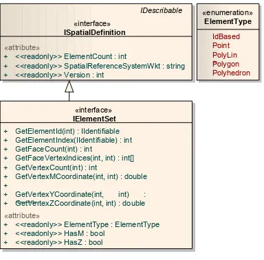
The Spatial Definition interfaces ... 26
6.4.1
Dependencies, attributes and methods for Spatial Definition interfaces ... 29
6.4.2
Requirements for Spatial Definition interfaces ... 32
6.5
The Temporal Definition interfaces ... 32
6.5.1
Attributes and methods for Temporal Definition interfaces ... 34
6.5.2
Requirements for Temporal Definition interfaces ... 35
6.6
The Value Set interfaces ... 36
6.6.1
Attributes and methods for Value Set interfaces ... 41
6.6.2
Requirements for Value Set interfaces ... 43
6.7
The Argument interface ... 43
6.7.2
Requirements for the Argument interface ... 45
6.8
Linkable Component Status ... 45
6.8.1
Attributes and methods for the Linkable Component Status Change Event Args class . 49
6.8.2
Requirements for Linkable Component Status ... 49
6.9
Input and output interfaces ... 50
6.9.1
Attributes and methods for Exchange Item interfaces ... 53
6.9.2
Requirements for Exchange Item interfaces ... 58
6.10
The Adapted Output interfaces ... 59
6.10.1
Attributes and methods for Adapted Output interfaces ... 61
6.10.2
Requirements for Adapted Output interfaces ... 63
6.11
The Manage State interfaces ... 64
6.11.1
Attributes and methods of the Manage State interfaces ... 64
6.11.2
Requirements for Manage State interfaces ... 66
6.12
Linkable Component ... 66
6.12.1
Attributes and methods for IBaseLinkableComponent interfaces ... 68
6.12.2
Requirements for Linkable Component interfaces ... 74
Annex A
Conformance Class Abstract Test Suite ... 75
Annex B
XSD Schema for OMI File ... 92
Annex C
XSD Schema for the Compliancy Information File ... 96
Annex D
OpenMi Association Intellectual Property Rights Policy, Trademark and Licences ... 110
Bibliography ... 111
Revision History ... 112
List of Figures
Figure 1
Linkages between components and the use of adaptors ... 2
Figure 2
A graphical view of the OMI file structure ... 16
Figure 3
UML Diagram for IDescribable and IIdentifible ... 18
Figure 4
UML Diagram for Value Definition ... 21
Figure 5
UML Diagram for Spatial Definition ... 28
Figure 6
UML Diagram for Temporal Definition ... 33
Figure 7
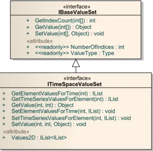
UML Diagram for Value Set ... 39
Figure 8
Illustration of directions to interpret positive values of fluxes, levels and
depths ... 40
Figure 9
UML Diagram for Argument ... 44
Figure 10 Component status change diagram ... 46
Figure 11 UML Diagram for Linkable Component Status ... 47
Figure 12 OpenMI Interfaces and the passage of data between two components ... 50
Figure 13 UML Diagram for Exchange Item ... 52
Figure 14 UML Diagram for Adapted Output ... 60
Figure 15 UML Diagram for Adapted Output Factory ... 61
Figure 16 UML Diagram for Manage State ... 64
Figure 17 UML Diagram for Linkable Component ... 68
List of Tables
Table 1
Members of the IDescribable interface ... 18
Table 2
Members of the IIdentifiable interface ... 18
Table 3
Base units in the OpenMI (derived from SI with an extension for currency) ... 22
Table 4
Members of the IValueDefinition interface ... 23
Table 5
Members of the IUnit interface ... 23
Table 6
Members of the IQuantity interface ... 23
Table 7
Members of the IQuality interface ... 23
Table 8
Members of the ICategory interface ... 24
Table 9
Members of the IDimension interface ... 24
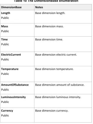
Table 10
The DimensionBase enumeration ... 25
Table 11
Dependencies for ISpatialDefinition ... 29
Table 12
Members of the ISpatialDefinition interface ... 29
Table 13
Members of the IElementSet interface ... 30
Table 14
The ElementType enumeration ... 32
Table 16
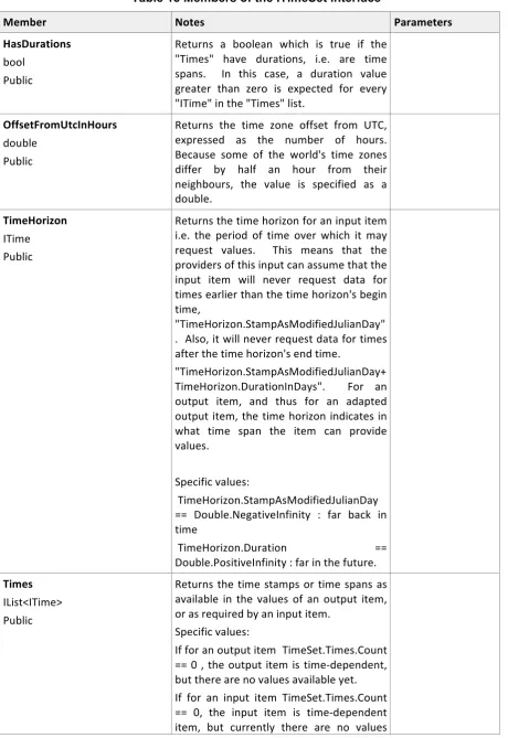
Members of the ITime interface ... 35
Table 17
Members of the IBaseValueSet interface ... 41
Table 18
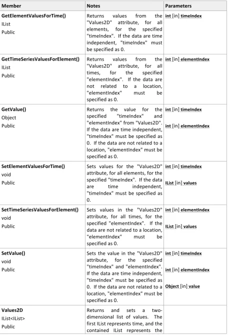
Members of the ITimeSpaceValueSet interface ... 42
Table 19
Members of the IArgument interface ... 45
Table 20
The LinkableComponentStatus enumeration ... 48
Table 21
Members of the LinkableComponentStatusChangeEventArgs class ... 49
Table 22
Members of the IBaseExchangeItem interface ... 53
Table 23
Members of the ExchangeItemChangeEventArgs class ... 54
Table 24
Members of the ITimeSpaceExchangeItem interface ... 54
Table 25
Members of the IBaseInput interface ... 54
Table 26
Members of the ITimeSpaceInput interface ... 55
Table 27
Members of the IBaseOutput interface ... 56
Table 28
Members of the ITimeSpaceOutput interface ... 58
Table 29
Members of the IBaseAdaptedOutput interface ... 62
Table 30
Members of the IAdaptedOutputFactory interface ... 62
Table 31
Members of the IManageState interface ... 65
Table 32
Members of the IByteStateConverter Interface ... 65
Table 33
Members of the IBaseLinkableComponent interface ... 69
Table 34
Members of the ITimeExtension interface ... 73
(i)
Abstract
The purpose of the Open Modelling Interface (OpenMI) is to enable the runtime exchange of data between process simulation models and also between models and other modelling tools such as databases and analytical and visualization applications. Its creation has been driven by the need to understand how processes interact and to predict the likely outcomes of those interactions under given conditions. A key design aim has been to bring about interoperability between independently developed modelling components, where those components may originate from any discipline or supplier. The ultimate aim is to transform integrated modelling into an operational tool accessible to all and so open up the potential opportunities created by integrated modelling for innovation and wealth creation.
This document defines the requirements that a component must meet to achieve OpenMI compliance. These comprise: 1) a very thin core set of requirements covering the information and functions needed to establish a link and make an exchange between two components and 2) a set of optional extensions for handling more complex situations.
The document does not describe how to implement the standard. This information together with a range of software tools for creating and running OpenMI‐compliant components are provided by the OpenMI Association and third‐party software vendors – visit www.openmi.org for further documentation.
(ii)
Keywords
OpenMI; Open Modelling Interface; standard; integrated modelling; model integration; model component; interface; model linking; model coupling; data exchange; API.
(iii) Preface
Attention is drawn to the possibility that some of the elements of this document may be the subject of patent rights. The Open Geospatial Consortium shall not be held responsible for identifying any or all such patent rights.
Recipients of this document are requested to submit, with their comments, notification of any relevant patent claims or other intellectual property rights of which they may be aware that might be infringed by any implementation of the standard set forth in this document, and to provide supporting documentation.
(iv) Submitting organizations
(v)
Submitters
All questions regarding this submission should be directed to the editor (see cover page, top right hand corner) or the submitters, who are listed below:
Name Representing OGC
member Email
Standa Vanecek OA and DHI No [email protected] Stef Hummel OA and Deltares Yes [email protected] Adrian Harper OA and Innovyze No [email protected]
om
Gennadii Donchyts OA and Deltares Yes gennadii.donchyts@deltar es.nl
Peter Gijsbers OA and Deltares Yes [email protected] Jesper Grooss OA and DHI No [email protected] Johan Hartnack OA and DHI No [email protected] Rob Knapen OA and Alterra,
Wageningen UR No [email protected] Onno Roosenschoon OA and Alterra,
Wageningen UR No [email protected] Peter Schade OA and BAW No [email protected] Jon Goodall OA and University of
South Carolina No [email protected] Andrea Antonello OA and Università di
Trento/ HydroloGIS No [email protected] Jan Gregersen OA and HydroInform No [email protected]
om
Simon Cox OA and CSIRO Yes [email protected]
Paul Cleverley OA and HR Wallingford Yes [email protected] Robert Szczepanek OA and Cracow University
of Technology / NT [email protected]
Roger Moore OA No [email protected]
David Fortune OA and XPSolutions No David.fortune@xpsolution s.com
Quillon Harpham OA and HR Wallingford Yes q.harpham@hrwallingford .co.uk
Robert Millington OA and Innovyze No robert.millington@innovyz e.com
David Lemon OA and CSIRO Yes [email protected] Andrew Hughes OA and NERC/BGS Yes [email protected] Bert Jagers OA and Deltares Yes [email protected] Michiel Blind OA and Deltares Yes [email protected]
1 Scope
1.1 Background
The Open Modelling Interface standard (more usually referred to as the OpenMI) makes possible runtime data exchange between independently developed modelling components. It is an enabling technology that facilitates the simulation of process interactions, where the interactions may either lie within or across the traditional boundaries of scientific disciplines. When the components are models, they may be simple or complex, be based on the same or different concepts and come from the same or different suppliers, whether commercial or open source.
The OpenMI's development has been co‐funded by the European Union through two projects (HarmonIT (EC contract: EVK1‐CT‐2001‐00090) and Open‐Life (Grant agreement number LIFE06 ENV/UK/000409)) and by the commercial and academic partners of those projects. They were managed by the Natural Environment Research Council (UK) with technical leadership coming from DHI (DK), Deltares (NL) and HR Wallingford (UK), the last with the assistance of its former subsidiary Wallingford Software (now Innovyze (USA)). Future development and the OpenMI's publication as an Open Geospatial Consortium international standard are now the responsibility of the OpenMI Association, which is a legal entity established under Dutch law to take ownership of the Intellectual Property Rights (IPR) relating to the OpenMI – see Annex D for details of the OpenMI Association's IPR policy in relation to the OpenMI standard.
1.2 What is it for?
The standard exists to enable the exchange of data between modelling components at runtime; components being anything from a single constant, e.g. Pi, via measurement devices, functions, models, databases, visualization tools and analytical tools, to complex 3D time‐variant modelling applications. In more practical terms, components can be anything necessary to build simulation models or decision support systems (DSS). These enable scientists to improve our understanding of the Earth as a system, help policy‐makers to find effective and sustainable responses to societal challenges, help entrepreneurs, consultants and developers to explore, develop and deliver new ideas, products and services and provide facilities for teaching and demonstrating our growing knowledge of a joined‐up world.
1.3 What is it?
The OpenMI is an interface standard and consists of a core group of requirements and optional extensions. The core is very thin and defines the requirements for describing components and the data they can exchange, linking and exchanging data; extensions deal with the more sophisticated data exchange requirements, such as those involving interactions over time and space. At the time of writing, there is one extension, the TimeSpace Extension, that forms part of the OpenMI 2.0 Standard. Clause 6 will explain which requirements are core and which are extensions.
The purpose of the core and extension concept is to allow for the future incremental development of the OpenMI. It is also intended to provide a path for its harmonization and integration with other known standards for example, those of the OGC®.
Users can develop their own extensions and are welcome to put these forward to the OpenMI Association for adoption as part of the formal standard. Such proposals should be made to the OpenMI Association Technical Committee ([email protected]) or be submitted via the OGC®.
1.4 What does it do?
These calls enable components to obtain ('get')1 the values of a variable from one component or
change ('set') them in another (at particular locations and/or times should the component compute values over time and/or space). Bi‐directional links are also possible (i.e. exchanges between two components can be made in both directions).
Adaptors are used to handle unit transformations and to handle differences in model temporal and spatial resolutions and representations (e.g. vector/raster/non‐spatial) – see Figure 1. Adaptors can also be designed to exchange data with model components using alternative interfaces.
Further details are available in What's New in OpenMI 2.0.
Figure 1 Linkages between components and the use of adaptors
1.5 How is the OpenMI implemented?
The process begins by analysing the component's description and code and identifying the variables2
whose values are to be 'accepted' from or 'provided' to other modelling components via the OpenMI interface. Some modelling components can accept or provide data for a variable at multiple locations, e.g. points in a grid or nodes in a network. In these cases, decisions are needed as to which of the locations are to be able exchange data with other components. It might be decided to expose only one or two points, e.g. the inlet and/or outlet of a process, or any number of points. Next, if the model component already exists as a callable entity, then the structure of its code needs to be examined. If the code is not in the form 'initialize, run, finalize', then the code must be rearranged into this pattern. This structure facilitates the handing over of partial control to the outside world. For example, it makes possible the design of interfaces that allow another component to request data and, if necessary, cause the component to run until it is able to provide the requested data. If the component does not exist, then it should be designed to have 'initialize, run, finalize' structure.
1 ‘Get’ in the context of the OpenMI covers the activities of ‘requesting’, ‘providing’ and ‘accepting’ the values
of exchange items.
Finally, the code is 'wrapped', i.e. given an OpenMI interface. There are two main options for doing this. One is to download the OpenMI software development kit (SDK) from the OpenMI Association website and/or use the available third‐party tools which simplify this task. These are available from the web at no charge under an open source licence. The other is to write your own code following the specification and the guidance in the user documentation available on the OpenMI Association website at www.openmi.org. The use of the tools is entirely optional and they do not form part of the standard.
Third‐party open source tools are also available for building and running compositions, i.e. a set of linked modelling components. The OA intends, subject to resources, to make a set of aids available should there be no third‐party software. The use of the tools is entirely optional and they do not form part of the standard.
1.6 Future development
1.6.1 Background
In 2008, the OpenMI Association (OA) was approached by the OGC® and asked if it would be prepared to publish the OpenMI Standard as one of the OGC® family of standards. Two reasons were given for the inquiry. The first was the increasing importance of the time dimension in the OGC's work and the consequent need to grow the OGC's knowledge and experience in this area; while the second was to address the growing need, common to all disciplines, to link sensors, datasets, models and related modelling components in order to understand and explore process interactions better. Such understanding could then be applied in improved simulation and decision support systems. It was the early perception of this latter need that led David Schell to found the OGC®.
The OpenMI Association welcomed the invitation because accreditation by an internationally‐ recognized standards organization would remove an important barrier to use of the OpenMI by public bodies and industry. It would also facilitate the uptake and development of integrated modelling, which is the OA's ultimate goal.
As the Association had just agreed a major upgrade of the OpenMI and was well on with the process of implementing that upgrade, the OGC® and the OA agreed that the starting point for their joint work would be the OpenMI Version 2.0. This was formally released at the International Summit on Integrated Environmental Modelling in Washington in December 2010. The period leading up to and just after the release was used to grow the relationship between the OA and the OGC® and, in particular, to work out how they would collaborate.
1.6.2 The OpenMI-OGC Memorandum of Understanding
The outcome of this period was a memorandum of understanding (MoU) on the way forward, the public and private sectors and ultimately the public. To do this a number of challenges must be overcome; these are:
Raising and maintaining awareness and building confidence in integrated modelling Establishing a minimum set of standards and ensuring their interoperability
Achieving a critical mass of linkable modelling components
Ensuring availability, accessibility and usability of integrated modelling techniques, tools and standards
1. OpenMI and OGC will develop procedures to co=operatively share relevant standards documentation necessary for the accomplishment of objectives under this agreement. Document sharing will be limited to designated representatives of OGC and OpenMI, and will be consistent with the policies and procedures of each organization.
2. OpenMI and OGC will work to jointly advance international consensus standards of mutual interest. A first priority will be the facilitation of OpenMI 2.0 as an open international consensus standard under the OGC process framework.
3. OpenMI and OGC will pursue the development of use cases of critical scientific and technical interest to their respective memberships.
4. OpenMI and OGC shall work jointly to develop architectural frameworks, extensions, ontologies, and service and model standards relevant to simulations and computational models, and their interoperability with each other and with OGC services and data models.
5. OpenMI and OGC shall collaborate on the development and conduct of outreach activities to raise awareness within and beyond their respective communities.
6. OpenMI and OGC shall investigate requirements and opportunities, including joint applications for funding, for advancement of model interoperability through joint testbeds, experiments, and pilot activities.
encompassing, will be imperfect and may well not be compatible with other standards. However, it will enable independent model developers to create linkable components. This is the purpose in making the OpenMI V2.0 an OGC® standard. It is expected that the initial rate of development will be slow but accelerating as competency and confidence grow. Once a critical mass of linkable components is in place rapid development can be expected. OpenMI‐compliant components with components using other interface standards. An immediate task will be to bring together the authors of other relevant interface standards, including those for modelling and sensors, in order to establish if operational versions of such adaptors can be designed and developed. This will further increase the pool of sensors and modelling components that can be linked. A number of the key players are already OGC® members.
Attention can then be turned to developing a detailed plan for addressing the longer‐term challenges. Quite detailed outline plans are known to exist among environmental and health modellers and almost certainly exist in other disciplines. These and the MoU above will form the starting point for the OA‐OGC plan.
While it would be wrong to anticipate the detail of that plan, it is almost certain that it will contain a review of all the current interface standards and take a forward look at where additional standards would help advance integrated modelling. If, as is almost certain to be the case, modifications or new standards are required, then these will be progressed through the OGC® Standards Working Group system. Where existing standards are used, the model established for incorporating and publishing NetCDF and the OpenMI as OGC® standards will be followed.
1.7 Further reading
The following OpenMI Association documents from The OpenMI Document Series provide further background reading and detailed information on its implementation:
What's New in OpenMI 2.0 (OpenMI Association, 2010)
The OpenMI 'in a Nutshell' for the OpenMI (Version 2.0) (OpenMI Association, 2010) Scope
for the OpenMI (Version 2.0) (Moore, et al., 2010)
Migrating Models for the OpenMI (Version 2.0) (OpenMI Association, 2010)
OpenMI Standard 2 Specification for the OpenMI (Version 2.0) (OpenMI Association, 2010) OpenMI Standard 2 Reference for the OpenMI (Version 2.0) (OpenMI Association, 2010) For further details, please see the Bibliography at the end of this document. The cited documents are available through the OpenMI Association website at www.openmi.org.
1.8 Document structure
The document that follows defines the Open Modelling Interface. Clause 2 sets out the rules for conformance. Clauses 3, 4 and 5 cover normative references3, terms and definitions, and
conventions. Clause 6 specifies in detail the classes for creating an Open Modelling Interface. Testing is described in the Annexes.
2 Conformance
To conform to this specification and hence be termed 'OpenMI‐compliant', a model component shall implement a set of interfaces that can connect to and interact with the OpenMI component interface "IBaseLinkableComponent" (or its specializations, e.g. the "ITimeSpaceComponent" for time and space dependent components). These interfaces are described in Clause 6 'OpenMI Requirements classes'.
The requirements for compliance are as follows:
1. An OpenMI‐compliant component shall implement the mandatory 'Core' requirements according to specifications provided in this document – see Clause 6.
2. The OpenMI Association provides two additional core interfaces that OpenMI‐compliant components may or may not implement: the "IManageState" interface and the "IByteStateConverter" interface. However, if these interfaces are implemented, each method and attribute shall be implemented according to the instructions given in this document.
3. An OpenMI‐compliant component may also implement one or more of the optional OpenMI extensions. If implemented, the implementation shall conform to the specifications provided in this document.
4. An OpenMI‐compliant component including its extensions shall, when compiled, reference the OpenMI.Standard2*.DLLs (.Net Framework 2.0 or higher) or OpenMI‐standard2*.jars (java 1.5 or higher). These DLLs/jars contain only interfaces. They are compiled and released by the OpenMI Association. The OpenMI Association's downloadable standard zip file provides the only recognized version of OpenMI Version 2 Standard interfaces.
If an OpenMI‐compliant component is to run in one or more of the existing GUIs for linking OpenMI‐ components, it shall be associated with an XML file, referred to as the 'OMI file', which conforms to and can be validated with the LinkableComponent.xsd schema – see Annex B.The interfaces are specified in language independent UML and are available in C# and Java. Both C# and Java compilers will ensure that the client code correctly calls the methods and will ensure type safety for the
objects obtained from the method call.
3 Normative References
The following normative documents contain provisions that, through reference in this text, constitute provisions of this document. For dated references, subsequent amendments to or revisions of any of these publications do not apply. For undated references, the latest edition of the normative document referred to applies.
1) OGC 08‐015r2, The OpenGIS Abstract Specification, Topic 2: Spatial Referencing by Co‐ ordinates, 2010‐04‐27.
http://portal.opengeospatial.org/files/?artifact_id=39049
2) Documents associated with Unified Modeling Language™ (UML®), August 2011. http://www.omg.org/spec/UML/2.4.1/
4 Terms and Definitions
In the context of the OpenMI and for the purposes of this document, the following terms and definitions apply:
Adaptee
An output exchange item whose values are to be adapted. In an OpenMI context 'adapt' means: to convert units of measurement
to aggregate or disaggregate output values over time or space to interpolate between output values over time or space
any other operation to convert the output of a providing model component to match the input requirements of the accepting model component.
Adaptor
In the OpenMI context, adaptors are used to convert the output values of the providing component to the form required by the requesting component. Adaptors can be used to handle any or all of unit conversions, spatial transformations and temporal transformations. Users can either use adaptors provided by third parties or write their own.
Compliancy information file
An XML file containing information about a component whose compliance you would like to be registered with and published by the OpenMI Association – see Annex C.
Component
See Model component.
Composition
A set of linked components set up to simulate a particular scenario.
Element
Data exchange between components in the OpenMI is nearly always related to one or more of a set of elements in a space that may or may not be geo‐referenced. For example, these elements might represent towns, pathways in the human body, segments of transmission lines or a cellular representation of the atmosphere or a water body for which values are requested or set – see also element set and version.
Element set
An element set can comprise any number of elements and the geometry of each element can be represented in any way from a one‐dimensional array of points, line segments, poly lines or polygons, through to an array of three‐dimensional volumes. As a special case, a cloud of Id‐based elements (i.e. they do not have co‐ordinates or their co‐ordinates are not being used) is also supported. This allows data exchange in contexts where spatial position is unimportant or irrelevant as might arise in an economic model – see also element and version.
Engine
A synonym for model component often used in OpenMI documentation.
Exchange item
values are qualitative: for example, 'hot' and 'cold' for temperature or 'sand', 'clay' and 'peat' for soil type.
Link
When used as a verb, it means to connect an output exchange item of one model component to an input exchange item of another.
Linkable component
A model component which implements the OpenMI "IBaseLinkableComponent" interface according to specifications provided in this document.
Model
A model component that has read in the data that describes the situation to be simulated, analysed, visualized or otherwise processed: e.g. a generic model component for simulating the flow of water down an open channel that has been set up to model the specific behaviour of all or part of the River Rhine under given conditions.
Model application
An entire modelling software system that can be installed on a computer.
Model component
A distinct part of a model application where computation takes place – in this context the 'computation' might be simulating a process, analysing or visualizing results or some other process. The computation may be very simple (for example, a linear equation) or extremely complex (for example, a dynamic model of airflow through the nose and mouth to the lungs).
Model linking
The process by which one or more data transfer links are established between the output exchange items of one model component and the input exchange items of another model component.
Modified Julian day
Modified Julian day is the Julian Day minus 2400000.5. A Modified Julian Day represents the number of days since midnight 17 November 1858 Universal Time on the Julian calendar. The Modified Julian Day has been selected as a reference, since few models operate in a time horizon before 1858. Any date before 17 November 1858 will be represented as a negative value.
(See RECOMMENDATION ITU-R TF.457-2. USE OF THE MODIFIED JULIAN DATE BY THE
STANDARD-FREQUENCY AND TIME-SIGNAL SERVICES – which may be found at:
http://www.itu.int/dms_pubrec/itu‐r/rec/tf/R‐REC‐TF.457‐2‐199710‐I!!PDF‐E.pdf)
OMI file
The OMI file is an XML file containing metadata about a component – see Annex B. Third‐party GUIs can use the information the file contains to simplify the linking of components.
Quality
In the context of the OpenMI, a quality usually refers to an exchange item whose values are qualitative (for example, 'hot' and 'cold' for temperature) or categorical (for example, 'sand', 'clay' and 'peat' for soil type).
Quantity
In the context of the OpenMI, a quantity usually refers to an exchange item whose values are numeric.
UTC
Version
5 Conventions
5.1 Identification
This document and the standard it defines follow the guidelines of the OGC® Naming Authority for all identifiers. The key identifiers are given below.
5.1.1 The external identifier of this OGC® document
This may be found at the top right hand corner of the front page of this document. 5.1.2 The identifier of this OGC® standard
This standard is identified as:
http://www.opengis.net/spec/openmi/2.0
5.1.3 The base URI for requirement and conformance classes
The base URI for all relative URIs that denote requirements and conformance classes is: http://www.opengis.net/spec/openmi/2.0
5.1.4 The OpenMI XML namespaces The namespace for OpenMI 2.0 is:
http://www.openmi.org/v2_0
The XML schema definitions (XSD) are located in: http://www.openmi.org/schemas/v2_0
5.2 Symbols (and abbreviated terms)
1D One dimensional
2D Two dimensional
3D Three dimensional
API Application programming interface
DSS Decision support system
DWG Domain Working Group of the OGC®
Id Identifier
GUI Graphical user interface
MoU Memorandum of understanding OA OpenMI Association
OATC OpenMI Association's Technical Committee
OCT OATC Conformance Tool
OGC Open Geospatial Consortium
OMG Object Modelling Group
OMI Open Modelling Interface OpenMI Open Modelling Interface
SDK Software development kit
SWG Standards Working Group of the OGC®
UML Unified Modelling Language
URI Uniform Resource Identifier
URL Uniform Resource Locator
UTC Co‐ordinated Universal Time (for most purposes this is the same as Greenwich Mean Time (GMT))
XML Extensible Markup Language
XSD XML Schema Definition
5.3 Unified modelling language (UML)
This document follows the Object Modelling Group's (OMG) recommendations and specifications for UML which may be found at http://www.omg.org/spec/UML/2.4.1/.
Specific UML terms used in this document or used to define other UML terms are:
Attribute A named property of a type. The UML diagrams explicitly identify those attributes that are 'read‐only'.
Class A description of a set of objects.
Enumeration A list of named values used as the range of a particular attribute type. For example, Colour = {Red, Green, Blue}.
Event A significant occurrence. An event has a location in time and space and may have parameters. In the context of state diagrams, an event is an occurrence that can trigger a state transition.
Instance An individual member described by a type or a class. Usage note: According to a strict interpretation of the metamodel, an individual member of a type is an instance and a member of a class is an object. In less formal usage it is acceptable to refer to a member of a class as an object or an instance.
Interface The use of a type to describe the externally visible behaviour of a class, object, or other entity. In the case of a class or object, the interface includes the signatures of the methods.
Member A part of a type or class denoting either an attribute or a method.
Method The implementation of an operation or service that can be requested from an object to effect behaviour. A method has a signature, which may restrict the actual parameters that are possible
Namespace A part of the model in which the names may be defined and used. Within a namespace, each name has a unique meaning.
Object An entity with a well‐defined boundary and identity that encapsulates state and behaviour. State is represented by attributes and relationships, behaviour is represented by methods. An object is an instance of a class.
Parameter The specification of a variable that can be changed, passed or returned. A parameter may include a name, type and direction. Parameters are used for methods, messages and events.
State A condition or situation during the life of an object during which it satisfies some condition, performs some activity or waits for some event.
Type A description of a set of instances that share the same methods, abstract attributes and relationships and semantics. A type may define a method specification (such as a signature) but not a method implementation. Usage note: Type is sometimes used synonymously with interface, but it is not an equivalent term.
http://www.iai.uni‐bonn.de/III/lehre/vorlesungen/SWT/SS96/Material/UML1.0/glossary.html#
5.4 Extensible Markup Language (XML)
This document follows the W3C recommendation of 26 November 2008 Extensible Markup Language (XML) 1.0 (Fifth Edition) which may be found at http://www.w3.org/TR/xml/.
6 OpenMI Requirements Classes
The OpenMI Standard comprises:
a set of 'Core' requirements classes
an extension set of requirements classes referred to as the 'TimeSpace' extension.
Listed below are the required classes and their component requirements for the Core and the TimeSpace extension. All the Core requirements must be implemented except those marked as optional. Implementation of the TimeSpace extension is optional but, if implemented, all its requirements must be met.
The requirements for each are as follows:
Name Core/
Extension
Mandatory/ Optional
Clause
Requirements Class 1: Component Instantiation #Clause 6.1
Requirement 1.1: Component Instantiation/Valid XML Core Mandatory #Clause 6.1
Requirements Class 2: Describable Identifiable #Clause 6.2
Requirement 2.1: Describable Identifiable/Describable Core Mandatory #Clause 6.2 Requirement 2.2: Describable Identifiable/Identifiable Core Mandatory #Clause 6.2
Requirements Class 3: Value Definition #Clause 6.3
Requirement 3.1: Value Definition/Value Definition Core Mandatory #Clause 6.3
Requirement 3.2: Value Definition/Unit Core Mandatory #Clause 6.3
Requirement 3.3: Value Definition/Quantity Core Mandatory #Clause 6.3
Requirement 3.4: Value Definition/Quality Core Mandatory #Clause 6.3
Requirement 3.5: Value Definition/Category Core Mandatory #Clause 6.3
Requirement 3.6: Value Definition/Dimension Core Mandatory #Clause 6.3 Requirement 3.7: Value Definition/Dimension Base Core Mandatory #Clause 6.3
Requirements Class 4: Spatial Definition #Clause 6.4
Requirement 4.1: Spatial Definition/Spatial Definition TimeSpace Mandatory #Clause 6.4 Requirement 4.2: Spatial Definition/Element Set TimeSpace Mandatory #Clause 6.4 Requirement 4.3: Spatial Definition/Element Type TimeSpace Mandatory #Clause 6.4
Requirements Class 5: Temporal Definition #Clause 6.5
Requirement 5.1: Temporal Definition/Time TimeSpace Mandatory #Clause 6.5 Requirement 5.2: Temporal Definition/Time Set TimeSpace Mandatory #Clause 6.5
Requirements Class 6: Value Set #Clause 6.6
Requirement 6.1: Value Set/Base Value Set Core Mandatory #Clause 6.6
Requirement 6.2: Value Set/Time Space Value Set TimeSpace Mandatory #Clause 6.6
Requirements Class 7: Argument #Clause 6.7
Name Core/ Extension
Mandatory/ Optional
Clause
Requirements Class 8: Linkable Component Status #Clause 6.8
Requirement 8.1: Linkable Component Status/Linkable Component Status Core Mandatory #Clause 6.8 Requirement 8.2: Linkable Component Status/Linkable Component Behaviour Core Mandatory #Clause 6.8 Requirement 8.3: Linkable Component Status/Event Status Changed Core Mandatory #Clause 6.8
Requirements Class 9: Exchange Item #Clause 6.9
Requirement 9.1: Exchange Item/Base Exchange Item Core Mandatory #Clause 6.9
Requirement 9.2: Exchange Item/Base Input Core Mandatory #Clause 6.9
Requirement 9.3: Exchange Item/Base Output Core Mandatory #Clause 6.9 Requirement 9.4: Exchange Item/Time Space Exchange Item TimeSpace Mandatory #Clause 6.9 Requirement 9.5: Exchange Item/Time Space Output TimeSpace Mandatory #Clause 6.9 Requirement 9.6: Exchange Item/Time Space Input TimeSpace Mandatory #Clause 6.9 Requirement 9.7: Exchange Item/Event Exchange Item Changed Core Mandatory #Clause 6.9
Requirements Class 10: Adapted Output #Clause 6.10
Requirement 10.1: Adapted Output/Base Adapted Output Core Mandatory #Clause 6.10 Requirement 10.2: Adapted Output/Times Space Adapted Output TimeSpace Mandatory #Clause 6.10 Requirement 10.3: Adapted Output/Adapted Output Factory Core Mandatory #Clause 6.10
Requirements Class 11: Manage State #Clause 6.11
Requirement 11.1: Manage State/Manage State Core Optional #Clause 6.11
Requirement 11.2: Manage State/Byte State Converter Core
Optional but requires the implement-ation of the Manage State Interface
#Clause 6.11
Requirements Class 12: Linkable Component #Clause 6.12
Requirement 12.1: Linkable Component/Base Linkable Component Core Mandatory #Clause 6.12 Requirement 12.2: Linkable Component/Time Space Component TimeSpace Mandatory #Clause 6.12 Requirement 12.3: Linkable Component/Time Extension TimeSpace Mandatory #Clause 6.12
In the following clauses the requirement class descriptions are grouped according to the aspect of the OpenMI to which they relate. Each description begins with a general introduction, which includes a table of the URIs for the requirement class and the specific requirements relating to it. This is followed by a UML diagram presenting the dependencies between the classes. Where appropriate, the UML diagram is supported by one or more tables describing the members (methods, attributes and events) of any interfaces. The description concludes with a table listing the specific requirements that must be met for compliance to be achieved.
that the description uses the concept of an 'attribute'. Some languages use the term 'property' and as the terms attribute and property are equivalent in this context, there is no problem. Other languages have no attribute concept. However, in these cases, the same functionality can be achieved through the use of methods or functions. Thus, an attribute "Caption" can be represented by two methods, "GetCaption()", which returns the caption value as a string and "SetCaption (string)" which assigns the value in the string to the caption. If the attribute is 'read‐only' then no 'Set' method is required.
Developers may find it helpful to view the supported implementations of the standard available in C# and Java and accessible via the OpenMI Association's website at www.openmi.org.
6.1 Component instantiation
An OpenMI Linkable Component is instantiated, for example, by loading a .NET assembly and creating an instance of a class that is incorporated into that assembly. The information on the assembly to be loaded and the class to be instantiated is specified in a registration file called the OMI file, which can be located anywhere on disk.
This file also holds the arguments that should be provided to the component when it is initialized. In addition to its interfaces, the OpenMI Standard therefore also defines an XML Schema Definition (xsd) for the OMI file. Figure 2 provides a graphical view of the file structure according to the XML Schema Definition. The full Schema Definition for the OMI file can be found in Annex B.
Figure 2 A graphical view of the OMI file structure
Requirements Class 1: Component Instantiation
/req/component‐instantiation
Target type OpenMI Component
Dependency
Requirement 1.1 /req/component‐instantiation/ValidXML
6.1.1 Requirements for Component Instantiation
Requirement 1.1: Component Instantiation/Valid XML
/req/component‐instantiation/ValidXML
An OpenMI component shall be described by a valid XML document that describes the arguments to be provided when the component is instantiated and initialized.
'Valid' means that the XML document should adhere to the XML schema definition as defined in http://www.openmi.org/schemas/v2_0/LinkableComponent.xsd, a copy of which can be found in Annex B.
6.2 The Describable and Identifiable interfaces
Many of the OpenMI interfaces describe entities to which users will need to refer through the user interface. Therefore, these entities need a caption and a more detailed description where a caption cannot provide all the information needed.
In addition, some interfaces describe an entity whose specific instances need to be referenced and these therefore also require descriptors and identifiers. An example of their use might be in establishing and storing a link between two components by pairing the identifier of a specific output exchange item of the providing component with a specific input exchange item of the accepting component.
To ensure consistency in the identification and description of all kinds of entity instances, two interfaces are provided: "IDescribable" and, derived from that, "IIdentifiable" – see Figure 3. The majority of the OpenMI Standard Version 2.0 interfaces are derived from one of these interfaces.
Requirements Class 2: Describable Identifiable
/req/describable‐identifiable
Target type OpenMI component
Dependency
Figure 3 UML Diagram for IDescribable and IIdentifiable
6.2.1 Attributes and methods for Describable and Identifiable interfaces
Table 1 Members of the IDescribable interface
Member Notes Parameters
Caption string Public
Sets and returns the value of the "Caption" attribute as a string (not to be used as an identifier).
Description string
Public
Sets and returns additional descriptive
information about the entity.
Table 2 Members of the IIdentifiable interface
Member Notes Parameters
Id string Public
Returns the value of the "Id" attribute as a string. The Id must be unique within its context but does not need to be globally unique: e.g. the Id of an input exchange item must be unique in the list of inputs of an "IBaseLinkableComponent", but an identical Id might be used by an exchange
Description : string
«interface»
IIdentifiable
«attribute»
Member Notes Parameters
item of another "IBaseLinkableComponent".
6.2.2 Requirements for Describable and Identifiable interfaces
Requirement 2.1: Describable Identifiable/Describable
/req/describable‐identifiable/IDescribable
An OpenMI class that represents a described entity shall implement the IDescribable interface based on the definition in Figure 3 and Table 1.
Requirement 2.2: Describable Identifiable/Identifiable
/req/describable‐identifiable/IIdentifiable
An OpenMI class that represents an identifiable entity shall implement the IIdentifiable interface based on the definition in Figure 3 and Table 2.
6.3 The Value Definition interfaces
The OpenMI leaves the modeller free to decide the names used to label exchange items. It does, however, require some minimal information to be provided about each exchange item, partly to reduce the chance of erroneous links being made and partly to check that unit conversions are provided where the output units of the providing component are different to those of the accepting component.
Requirements Class 3: Value Definition
/req/value‐definition
Target type OpenMI component
Dependency /req/describable‐identifiable/IDescribable
Requirement 3.1 /req/value‐definition/IValueDefinition
Requirement 3.2 /req/value‐definition/IUnit
Requirement 3.3 /req/value‐definition/IQuantity
Requirement 3.4 /req/value‐definition/IQuality
Requirement 3.5 /req/value‐definition/ICategory
Requirement 3.6 /req/value‐definition/IDimension
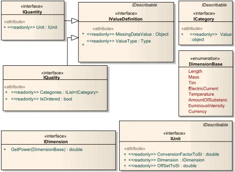
Figure 4 UML Diagram for Value Definition
The "IValueDefinition" interface establishes the data type of a specific exchange item's values and how those values will be represented when missing, e.g. by '‐9999'. A value definition is an IDescribable and therefore has a caption, for example 'Flow', and a description (more extensive information for correct interpretation of the caption and other information such as units, etc.) The "ValueType" attribute indicates the type of object returned when retrieving one of the values of the set, i.e. the value for a certain element and time. Typical values of the "ValueType" attribute will be "double", "bool", "string" or a dedicated class type. Further details will follow below in the descriptions of the "IQuantity" and "IQuality" interfaces.
One of the inheritors of the"IValueDefinition" interface is the "IQuantity" interface. This interface applies to exchange items whose values are numerical and have a "ValueType" of, for example, "double", "int", "boolean" or a class type. It also establishes the units of measurement in which values of the exchange item will be accepted or returned.
The "IUnit" interface provides additional information for checking that linked quantities have the same dimensions and unit conversion. For a given value v of a specific exchange item variable, the
<<readonly>> Categories : IList<ICategory> <<readonly>> IsOrdered : bool
«interface»
<<readonly>> MissingDataValue : Object
<<readonly>> ValueType : Type
«enumeration»
ElectricCurrent Temperature AmountOfSubstanc
e
LuminousIntensity Currency
«interface»
IDimension
+ GetPower(DimensionBase) : double
IDescribable
«interface»
IUnit
«attribute»
+ <<readonly>> ConversionFactorToSI : double + <<readonly>> Dimension : IDimension + <<readonly>> OffSetToSI : double
IDescribable
«interface»
ICategory
«attribute»
+ <<readonly>> Value : object
IQuantity
+
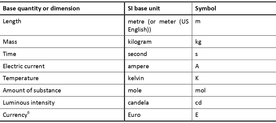
The "IDimension" interface has been defined to enable physical dimension4 checks between
quantities. A dimension is expressed as a combination of the basic dimensions, derived from the SI system5. A minor extension has been made for currencies. Table 3 illustrates the base
quantities/dimensions and the associated SI units. The "IUnit" interface provides a method to obtain the power for each base dimension of a specific exchange item. For example, a discharge expressed in units of m3/s has dimension Length3Time‐1 for which the method would return 3 and ‐1.
A further method checks if the dimensions of two exchange items are equal.
Table 3 Base units in the OpenMI (derived from SI with an extension for currency)
Base quantity or dimension SI base unit Symbol
Length metre (or meter (US
English)) m
Mass kilogram kg
Time second s
Electric current ampere
A
Temperature kelvin K
Amount of substance mole
mol
Luminous intensity
candela cd
Currency6 Euro E
Note that some units are dimensionless, represent logarithmic scales or present other problems when expressed in SI. In such cases, extra attention should be paid to the descriptive part of the unit, to ensure that a user defining a link has a proper understanding of the meaning of the values for the given exchange item.
The other inheritor of the "IValueDefinition" interface is the "IQuality" interface and it applies to exchange items whose values are qualitative. The "IQuality" interface specifies the list of categories used to record the state of the variable: for example, 'hot' and 'cold' for temperature or 'sand', 'clay' and 'peat' for soil type. The "ValueType" for these values will be "string".
The "IsOrdered" attribute indicates whether or not an ordering can be recognized in the categories. If "IsOrdered" is True, one category represents a 'higher' value than another category. The sequence 'very light', 'light', 'heavy', 'very heavy' is an example of an ordered categorization.
4 A dimension describes the type of thing being measured, without specifying the magnitude. Thus the
centimetre, kilometre, inch and foot all have dimensions of length.
5 More information on the SI system can be found at the National Institute of Standards and Technology
(http://physics.nist.gov/cuu/Units/).
6 Currency has no base quantity in the SI system. Note that currency has conversion units that may vary over
6.3.1 Attributes and methods for Value Definition interfaces
Table 4 Members of the IValueDefinition interface
Member Notes Parameters
MissingDataValue Object
Public
Returns the value of the "MissingDataValue" attribute representing "GetValues()" method of the "IBaseExchangeItem".
Table 5 Members of the IUnit interface
Member Notes Parameters
ConversionFactorToSI double
Public
Returns the conversion factor to SI units 'A' in the expression:
SI‐value = A * quantity‐value + B
Returns the offset to SI units 'B' in the expression:
SI‐value = A * quantity‐value + B
Table 6 Members of the IQuantity interface
Member Notes Parameters
Unit
Table 7 Members of the IQuality interface
Member Notes Parameters
Categories IList<ICategory> Public
Returns a list of the possible category values allowed for this quality. If the categories are not ordered, the list contains the category values in an unspecified order. When it is ordered the list contains the category values in sequence.
Member Notes Parameters IsOrdered
bool
Public
Returns a boolean indicating whether or not the quality is defined by an ordered set of category values.
Table 8 Members of the ICategory interface
Member Notes Parameters
Value Object Public
Returns the value for this category.
For example "blue" from the allowed set of values "red", "green" and "blue".
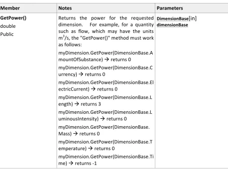
Table 9 Members of the IDimension interface
Member Notes Parameters
GetPower() double Public
Returns the power for the requested dimension. For example, for a quantity such as flow, which may have the units m3/s, the "GetPower()" method must work