M. Hess *, S. Robson
Department of Civil, Environmental and Geomatic Engineering, University College London, Gower Street, London,
WC1E 6BT UK – [email protected] , [email protected]
Commission V, WG V/2
KEY WORDS: 3D imaging, museum documentation, close range, laser scanning, cultural heritage, comparison, inspection
ABSTRACT:
3D colour image data generated for the recording of small museum objects and archaeological finds are highly variable in quality and fitness for purpose. Whilst current technology is capable of extremely high quality outputs, there are currently no common standards or applicable guidelines in either the museum or engineering domain suited to scientific evaluation, understanding and tendering for 3D colour digital data.
This paper firstly explains the rationale towards and requirements for 3D digital documentation in museums. Secondly it describes the design process, development and use of a new portable test object suited to sensor evaluation and the provision of user acceptance metrics. The test object is specifically designed for museums and heritage institutions and includes known surface and geometric properties which support quantitative and comparative imaging on different systems. The development for a supporting protocol will allow object reference data to be included in the data processing workflow with specific reference to conservation and curation.
1. INTRODUCTION
1.1 3D image libraries for museum objects?
After two decades of well funded and orchestrated 2D digitization of libraries and archives, museums now start to explore 3D object digitization for significant numbers of objects and the creation of 3D library content for detailed documentation, scientific and comparative analysis; public engagement both on site and remotely via the Web.
3D object libraries of selected artefacts are increasingly being integrated into publicly accessible websites, for example Musee Branley (Musée du quai Branly 2012) and the Museum of Sheffield (Museums Sheffield 2012). More broadly, projects such as Europeana are researching semantic 3D shape search to make 3D data available over the internet (Europeana 2012). As a further output 3D prints from 3D data of the originals and reconstructions can enhance the understanding of objects and be part of display and exhibition (Hess & Robson 2011).
The obvious innovative possibilities for teaching, learning and research have been discussed in (Robson et al. 2012). As an example, new apps, augmented reality and gesture tracking to view 3D objects are currently developed and tested in-house at the UCL Petrie Museum of Egyptian Archaeology (Nelson & MacDonald 2012).
We are just at the beginning of this new movement towards 3D image libraries. The technology of 3D non-contact optical surface recording is well suited to conservation documentation and complements other analytical imaging techniques. But the creation of 3D objects has not yet been integrated into the museum and conservation laboratory workflow. For many managers and curators 3D imaging resides under the label of ‘expensive and time intensive methods’ with uncertain outcome and low efficacy versus well-proven conventional documentation and assessment methods.
1.2 Motivation for a new heritage test object
The concerns of museum professionals are reasonable: whilst low cost systems are emerging, 3D imaging sensors are still expensive, workflows require craft orientated techniques and data quality are highly variable in outcome and fitness-for purpose. Best practice recommendations or specifications for tendering 3D imaging have been developed for built heritage and sites (Bryan et al. 2009) (Beraldin et al. 2011), but guidelines and best practice specifications for the 3D imaging of museum objects do not yet exist.
For sustainable planning and costing the outcomes of a 3D imaging campaign must be predictable. Movement, handling and digitization might be a ‘once in a lifetime’ event for a unique and precious museum object and need to be compliant with museum ethics (Hess & Robson 2010, sec.3.1)
A first step toward better integration of 3D imaging into the museum workflow is to equip the stakeholders with a tool to conduct a comparison of the sensors on offer. An informed decision can be taken for a technology that best suits their specific requirements for data capture, before an expensive investment or a task tendered to a consultant. Sensor technologies and software are subject to continuous technological improvement. Sustainable 3D colour imaging of a collection requires a standardised object and validation protocol against which long term outputs can be judged.
This paper describes the development and use of a portable test object suited to both sensor evaluation and the provision of user acceptance metrics. Evaluation criteria include resolution, form, colour fidelity and sensor mobility and make use of existing standards and good practice guides from engineering metrology, photography and psychophysical experiments.
2. DEVELOPMENT OF A PORTABLE TEST OBJECT
2.1 Requirements from curators and conservators feeding into the test object design
Museum objects can be characterised as individually hand-crafted artefacts with finest detail. The ultimate requirement for 3D digital documentation in the museum has the aim of creating a 3D digital surrogate of the real object. Ideally this should be created by non-contact and non-invasive methods, but must certainly be to correct scale with scientific geometry and colour recording at a spatial resolution that can accommodate the finest detail on the object. Often only a combination of 3D imaging sensors will lead to satisfying information about colour, material properties and geometry.
The range of practical models encompasses the digital surrogate through to low quality models matched to the imaging capabilities of the current generation of mobile computing devices. One of the most discerning audiences are curators and conservators who are usually visually highly trained professionals able to discern the smallest details and visual errors. The minimum requirement for a ‘valuable 3D asset’ must meet visual inspection as with the real object, be supported by comprehensible documentation, and must show quantifiable evidence of geometric and colorimetric fidelity.
This paper is presented in the context of preliminary user testing whereby 3D records have been presented to a variety of museum professionals (Hess et al. 2011). In this audience, common themes, which highlight conservation requirements for 3D recording and later visualization have been found to be as follows:
1. Dimensionally correct reproduction of the original object. To support for example: Quantitative and qualitative comparison between objects of similar type and purpose. Also likely to be required are cross sections of the object at any location and orientation and the computation of volume.
2. Traceable object colour with the option to track colour changes over time
3. Detailed metric visualization of object material and damage.
4. Evidence and subsequent monitoring of dimensional change/ depth/ width of cracks. Capability to accurately determine the height of a physical step or smallest distinguishable step of a paint layer.
Such a model may provide the spatial framework for early diagnosis of artefact deterioration and treatment based on a range of scientific recording technologies, as described in (Robson et al. 2004), (Drewello et al. 2006) and (Robson et al. 2008).
2.2 Existing guidelines and parameters for the design of the artefact
Engineering metrology is founded on quantification rather than qualitative assessment and can provide a framework within which different sensors can be examined and compared. How-ever even in this relatively mature science an accepted termi-nology and methodology remains very much in- progress (Ber-aldin et al. 2007). Engineering guidelines for optical non-contact measurement are slowly maturing and are characterised by geometric surfaces and recording device independent (VDI/VDE 2617/ part 6.2, VDI/VCI 2643, ISO 10360-8, ASTM E 57 is in development). Guidelines for gloss measure-ment are available from NPL UK (Hanson 2006); whilst ISO-16067-1 provides guidelines for the assessment of resolving power.
The test object design was inspired by existing work: (Robson et al. 2011) is reporting about artefacts for optical surface measurement for manufacturing industry and engineering; The test object described in this paper has been developed for the verification and comparison of geometry, colour and spatial resolution produced by 3D optical measurement systems and draws upon many of the surface form characteristics exploited during an earlier project to develop a set of highly specific validation artefacts for nuclear tile inspection (Brownhill et al 2009). More recently (Beraldin et al. 2009); (MacKinnon et al. 2011) have reported developments towards a portable target case for metrology at NRCC.
2.3 Overview of test object design
A new test object for museum use should take above conservation and curation criteria and requirements into account. The overriding challenge is that the optical characteristics of each reference surface should be close to lambertian so that each feature can be imaged without the need for paint layers or white spray.
The use of the object is driven by a series of procedure tests that can accommodate different close range 3D imaging systems and should represent a general transferable case for the testing of dimensional properties, surface geometry, colour and resolving power. The object design also needs to provide thermal and dimensional stability whilst remaining portable. In use, a significant advantage is provided by an object that can be precisely manipulated to present surface features at consistent angles to the sensing system under test.
2.4 First ideas for heritage test object design
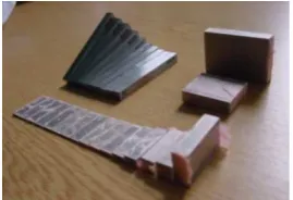
Initial design aimed to meet this broad range of requirements by bringing together a collection of bespoke and off-the-shelf objects and test patterns into a common physical system. In our
Figure 1. Mock-up of test object: set of Steel Slip Gauge Set M32, Calibration Grade 1 and Angle Block Set, length gauges to test step height and as length bar (www.mscjlindustrial.co.uk).
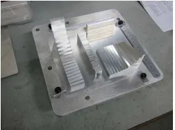
Figure 2. Inset plates with the calibrated tooling balls during the manufacturing process.
case this consists of a sphere and circular target image equipped reference frame for consistent registration. The frame then provides the physical reference onto which a series of secondary plates supporting step, gap, resolution and colour evaluation can be reproducibly attached.
A variety of off-the-shelf components for industrial inspection were procured and tested for their suitability for geometric test features. Objects included calibrated class 1 slip gauges, a set of angle gauges (Figure 1) and surface roughness standards. Their surface being hardened stainless steel surface treatment for 3D laser scanning would require vapour blasting. While this option should be considered for museums, at UCL the well equipped workshop was able to manufacture bespoke components by digitally programmed milling of aluminium alloy instead.
2.5 Heritage test artefact design. Description and materials.
The heritage test artefact was designed in CAD (Figure 4) and is composed of a 235mm x 235mm planar base plate into which three secondary plates can be inserted, each equipped with structures and patterns suited to both testing and object support. Situated around the base plate are an irregular array of six 20mm diameter individually calibrated tooling balls made of aluminium oxide mounted onto conical aluminium bases. The white matt surface of these ceramic balls provide a good surface for optical measurement whilst the conical base allows a high degree of sensor access to obtain maximum sphere surface cov-erage.
Below the base plate a threaded plate has been used to allow the object to be mounted onto a variety of goniometric, rotary and linear motion stages at UCL and other metrological tables in order to support accurate change in angle to sensing systems under test. With the exception of the spheres (Alumina Oxide Al203 matt), all components are made of Alcoa aluminium alloy T6061.
Once assembled the object dimensions need to be calibrated. In the UK a reference measurement service based on touch probe coordinate measurement machine is provided by the National Physical Laboratory.
The three secondary target plates (Figures 2 and 3): A ma-chined offset in the middle of the base plate allows three varia-tions of 4mm anodized aluminium target plate to be fitted. Each secondary plate is equipped with an irregular array of photo-grammetric targets so that it can be spatially referenced inde-pendent of the base plate if required.
1) 2D photographic target plate to test for resolution, colour and gloss (see Figure 5).
2) 3D geometric target plate, to test sensor geometry and dimensional capabilities (see Figure 6).
3) Artefact plate, comprising a magnetic plate inset under plastazode, an inert museum conservation material. This combination allows museum objects to be placed on top and held in place with plastazode coated magnets.
2D / photographic target plate: Spatial resolution is of importance for both conventional photography and 3D object recording. As such it is possible to use conventional photographic test procedures. The 2D photographic target includes established photographic test materials designed to assess resolution (ISO-16067-1), colour (x-rite Mini-Macbeth) and gloss (Figure 5).
Museum object have different shininess depending on their ma-terial and surface treatment. A selection of photographic paper of different Gloss Values was selected. The gloss value was measured with the Gloss meter by Sheen instruments (20/60/85 degrees). As gloss reference the new NCS gloss scale (a fan with of white, light grey, mid grey and black, each seven gloss levels) should replace the temporary gloss test fields.
The 3D geometric target plate (Figures 6 and 11) supports evaluation of the following parameters, parameters after (Carrier et al. 2011): dimensional characteristics, form characteristics, orientation characteristics, localization characteristics, profile characteristics, parameters for procedure. The geometric surface features comprise
Angle Artefact: a series of planar surfaces in two aluminium blocks. The planar surfaces provide varying angles to the base from 0o through to 30o.
Step artefact: adjacent blocks with nominal step height difference between 0.01 and 20.0 toprovide information about the capabilities of the measurement systems to measure steps/flush.
Length Control: two scale bars 75.0 long x 30mm high, and 150 mm long x 10mm high to provide dimensional control in conjunction with a surface temperature probe.
Gap artefact: eight individual blocks of the same height in combination with a series of seven blocks which present seven slots with nominal depth of 20mm and widths of: 0.1, 0.2, 0.3, 0.5, 1.0, 2.0, 3.0 mm.
2.6 Test object surface treatment: alkaline etching
There are several affordable options for preparing a metal surface to be compliant with optical surface 3D imaging of which the following are the most common: Coating with opaque spray, e.g. Spotcheck SKD-S2 developer; Vapour blasting; Surface treatment by etching.
Given our prior experience with surface etching (Brownhill et al 2009) a series of aluminium T6061 test cubes were manufactured using the same mechanical surface finishing
Figure 4. Technical drawing (CAD) of the geometric base plate
Figure 5. The completed 2D photographic target plate: Left ISO-16067-1 chart to test resolving power, top right: x-rite colour chart, bottom right: gloss scale.
Figure 10. Mock-up for test scan before surface treatment: Angle artefact in two blocks, step artefact in two blocks. Length bars, gap artefact. Bottom left: gauge and does not belong to array.
Figure 11. 3D colour laser scanning with an Arius3D Foundation system mounted on a Newport Goniometric Stage. The capabilities of the scanner are given in (Hess et al. 2011)(http://www.arius3d.com/a3d_specs.html)
Figure 12. Nikon handheld MMD and Krypton K610 Camera for 3D scanning of test object. Specification are given in (Hess & Robson 2010) (www.nikonmetrology.com)
Figure 7. Surface treatment by alkaline etching in the lab: suspending the test cubes in the sodium hydroxide solution.
Figure 8. Test cubes after trial run for alkaline etching lined up for test 3D scan additionally to mechanical clocking.
Figure 9. Artefact lined up for etching.
After the etching process the single element were mounted into a fixed position (see Figure 6).
process as for the since and since this can be repeated in a well equipped lab.
For the etching process and for the removal of 6-10 microns of surface materials the aluminium cubes were submerged in a solution of sodium hydroxide, the reaction was neutralized in a solution of nitric acid (Figure 7). The test cubes were used to produce an etching time series. This confirmed that with increasing exposure to the etching process a controlled surface roughness change could be introduced (Figure 8). Mechanical clocking was used before and after the process to determine the amount of material removed.
The cubes were scanned with an Arius3D Foundation System scanner to confirm which surface treatment would yield the best results for further treatment. (NRCC-CNRC 3D imaging metrology & Beraldin 2012) is currently preparing a report in collaboration with UCL about these samples about abrasive surface treatment applied to metallic artefacts.
After surface treatment all artefacts were then mounted onto the 3D Geometric base plate (Figure 12).
3. QUANTITATIVE AND COMPARATIVE IMAGING – PRELIMINARY TESTS
The preliminary test compares two 3D data sets of the heritage test object with geometric base plate created with state of the art sensors at UCL:
a) Arius3D Foundation model 150 laser scanner (mounted on a CMM) designed for recording small objects with volumes of the order of 0.5m3 and
b) Nikon handheld laser scanner MMD 100 with Krypton K-CMM 610 camera. This system has a very high quality triangulation scan head which is tracked by an optical system allowing the portable scanner to record much larger objects than the Arius3D system, but at lower accuracy (Figures 11 and 12).
3.1 Sphere fitting/ sphere diameter errors
Inspection and analysis to the 3D measurements of the six spheres around the base plate was carried out using the freely available PTB certified GOM Inspect V7 SR2 software (http://www.gom.com/3d-software/gom-inspect.html) and allows a verification of how well the individual components on the artefact can be located for subsequent testing with each system.
Unconstrained sphere fitting by Gaussian best-fit was applied to the six test artefact spheres of the captured with each system to provide a centroid location for each sphere. Nominal spheres were subsequently constructed with constrained Gaussian best-fit using the sphere reference diameters supplied by the sphere manufacturer.
Whilst the portion of the sphere captured (coverage) is similar with both systems, the different scanning system configurations result in the Nikon system delivering about 9% of the number of points provided by the Arius3D unit. The challenging geometry of the test object and their placement on the 3D geometry plate contributed to better scan results for spheres A and C in both systems throughout all tests.
Sphere fit residuals and standard deviations (Sigma) are more variable for the Nikon MMD with a Sigma of max. 0.26mm (sphere A) and a min of 0.08mm (sphere B), average of 0.14mm. These are attributable to the more irregular handheld scan head motion and the uncertainty budget of the optical tracking system given the range from camera to object of 5m. Arius3D sigma values remain consistently under 0.020mm (Figure 13). Both 3D scanners are therefore performing within their specifications.
For sphere diameter error analysis following comparisons were conducted (Figures 14 and 15):
Figure 13 Sigma values for sphere fitting in [mm]
Figure 14 Sphere diameter values, absolute values in [mm]
Figure 15 Sphere diameter difference in [mm]
Figure 16 Sphere spacing error, Arius3D vs Nik.MMD in [mm]
Figure 17 Plan of spheres A-F (green) and distance measurements (blue) seen in plan (Z+ axis)
Figure 18 Comparison Arius3D scan vs Nikon MMD. Scale covers a +/- 0.5mm range and demonstrates systematic discrepancies between the two sets of measurement data. (Cloudcompare, http://www.danielgm.net/cc/ ) nominal value against Arius3D dataset,
Results: Arius3D: showed an average deviation for sphere diameter of 0.024mm with a max at 0.045mm (sphere F) and a min of 0.017mm (sphere B) discrepancy to the CRV. (Figure 13, red squares).
b)CRF vs Nikon MMD dataset,
Results: Nikon MMD had an average diameter deviation of 0.156mm with a max of 0.218mm (sphere C) and a min of 0.087mm (sphere A). (Figure 13, blue square)
c) Arius3D against Nikon MMD dataset.
Resultsfollow comparison a) with the smallest value for sphere A, and the largest deviation for sphere F (Figure 13, green square).
Overall the spheres A and E showed the least, and sphere F show the largest deviation. As expected from the system designs, the CMM based Arius3D system performed the most consistently at this scale. Whilst the Nikon results demonstrate the trade-off made to achieve large volume portability.
3.2 Sphere spacing error
For the sphere spacing error 3D distances between centroids were computed and inter compared. These data, extracted in a similar manner to that described by VDI/VCI 2643 Part 2, allow an inter comparison of the scale error in the systems.
The distance deviation between both measurements was +/- 150 microns, the longest distance, a diagonal measurement lies well in the average deviation of 0.015 mm (Figures 16 and 17).
3.3 Observations on 3D laser scanning of test object
The test artefact was constructed to cater for object readily held in the hand or sections of larger objects that required imaging at a high level of detail. Sensors for this type of work are characterised by triangulation and fringe projection technologies with small depth of field. During the scanning process it could be confirmed that the construction of the test object posed considerable problems for sensors with a small depth of field. Where the hand-held Nikon was easily able to capture the complete surface of the test object in a relatively short time, the recording with Arius3D was more difficult to achieve due to the need for many separate scan records. As can be seen in Figure 18, there is a scale discrepancy between the sphere locations and this can only be resolved through an independent probe based measurement which will be carried out at the UK’s National Physical Laboratory in the near future. Also to note in the figure are bright boundary locations where there is no Arius3D data.
4. CONCLUSIONS
The discussed heritage test object is specifically designed for use by museums and heritage institutions and includes known surface and geometric properties which support quantitative and comparative imaging on different systems.
Work is on-going to develop the validation protocol in order to provide a practical guideline for evaluating several fundamental imaging principles including: high-resolution 3D colour laser scanning, close range digital photogrammetry, handheld laser scanning and fringe projection. The supporting protocol will allow object reference data to be included in the data processing workflow and is supported by user testing by museum professionals with specific reference to conservation and curation.
digitizing process for the creation of digital surrogates and digital assets which are fit for purpose and augment understanding about the value of their artefacts. This capability will ensure that high end 3D content generation is fit for the intended purpose and that data captured today is sustainable for a wide range of scientific uses into the future.
REFERENCES
Beraldin, J.A., Picard, M., Bandiera, A., Valzano, V., Negro, F., 2011. Best practices for the 3D documentation of the Grotta dei Cervi of Porto Badisco, Italy. In: Three-Dimensional Imaging, Interaction, and Measurement. San Francisco Airport, California, USA, p. 78640J–78640J–15. http://spie.org/x648.html?product_id=871211 (4 August 2011). Beraldin, J.-A., Cournoyer, L., Picard, M., Blais, F., 2009. Proposed procedure for a distance protocol in support of ASTM-E57 standards activities on 3D imaging. In: Three Dimensional Imaging Metrology Conference. San Jose, CA, USA: SPIE-International Society for Optical Engineering, p. 72390S–72390S–12.
Beraldin, J.-A., Blais, F., El-Hakim, S.F., Cournoyer, L., Picard, M., 2007. Traceable 3D Imaging Metrology: Evaluation of 3D Digitizing Techniques in a Dedicated Metrology Laboratory. In: Proceedings of the 8th Conference on Optical 3-D Measurement Techniques. Zurich, Switzerland.
Brownhill, A., Brade. R., Robson, S., 2009. Performance study of non-contact surface measurement technology for use in an experimental fusion device. In: Proceedings of SPIE - The International Society for Optical Engineering, 7447.
Bryan, P., Blake, B., Bedford, J., Mills, J., 2009. Metric Survey Specifications for Cultural Heritage (English Heritage), 2nd ed., Swindon, UK: English Heritage. http://www.english-heritage.org.uk/publications/metric-survey-specification/ (2 December 2009).
Carrier, B., McKinnon, D., Cournoyer, L. Beraldin, J.-A., 2011. Proposed NRC portable target case for short-range triangulation-based 3D imaging systems characterization. In: Three-Dimensional Imaging, Interaction, and Measurement. San Francisco Airport, California, USA, p. 78640L–78640L– 13.
Drewello R., Fundel S., Hess M., 2006. Interdisciplinary research project. Fragmentary Mural Paintings; Digital Documentation, Possibilities of Aesthetic Presentation and Exemplary Communication. In: 7th European Commission Conference; Saveur. Prague, Czech Republic: ITAM, European Communities, pp. 427 – 437.
Europeana, 2012. Europeana Professional - New ways of searching and browsing: Europeana 4D and Assets 3D search. http://pro.europeana.eu/web/guest/thoughtlab/new-ways-of-searching-and-browsing (29 April 2012).
Hanson, A.R., 2006. Good practice guide for the measurement of gloss., National Physical Laboratory, NPL.
Hess, M., Simon Millar, F., Robson, S., MacDonald,S., Were G., Brown, I., 2011. Well Connected to Your Digital Object? E-Curator: A Web-based e-Science Platform for Museum Artefacts. Special Issue about cyberinfrastructure for the arts
and humanities and the digital object. Literary and Linguistic Computing, 26(2), pp.193 –215.
Hess, M., Robson, S., 2010. 3D colour imaging for cultural heritage artefacts. In: International Archives of Photogrammetry, Remote Sensing and Spatial Information Sciences, Vol. XXXVIII, Part 5, pp.288 – 292.
Hess, M., Robson, S., 2012. Re-engineering Watt: A case study and best practice recommendations for 3D colour laser scans and 3D printing in museum artefact documentation. In: D. Saunders et al., eds. Proceedings of Lacona IX - Lasers in conservation of artworks. London, UK: Archetype. Available at: http://www.lacona9.org/publication.php. (1 April 2012). MacKinnon, D., Beraldin, J.-A., Cournoyer, L., Carrier, B., 2011. Hierarchical characterization procedures for dimensional metrology. In: Three-Dimensional Imaging, Interaction, and
Measurement. San Francisco Airport, California, USA, p.
786402–786402–15.
http://spie.org/x648.html?product_id=872124 (August 4, 2011). Musée du quai Branly, 2012. Musée du quai Branly - collection 3D. http://modules.quaibranly.fr/collections-3d/index_en.html (29 April 2012).
Museums Sheffield, 2012. Objects in 3D : Museums Sheffield. http://www.museums-sheffield.org.uk/collections/objects-in-3d/ (1 April 2012).
Nelson T., MacDonald S. (2012). A space for innovation and experimentation: University Museums as test beds for new digital technologies. In: S. S. Jandl & M. S. Gold, eds. Academic Museums Takes Shape. MuseumsEtc. http://www.museumsetc.com/blogs/news/5296302-academic-museums-takes-shape. (1 April 2012).
NRCC-CNRC 3D imaging metrology, Beraldin J.A. (2012). Report: Characterization of surface abrasion methods using 3D imaging. 3D acquisition and analysis of surface samples characteristics for the purpose of understanding abrasive methods applied to metallic artefacts.
Robson, S., Bucklow, S., Woodhouse, NG., Papadaki, H., 2004. Periodic photogrammetric monitoring and surface reconstruction of a historical wood panel painting for restoration purposes. In: International Archives of Photogrammetry and Remote Sensing. Istanbul. 35: 395-401.
Robson S., Rova M., Morgan L., Heuman J., Heathcote M., Lees D., Caner H., Gotthardt-Mills C. (2008). Measurement of transparent plastic sculptures using photogrammetry, laser scanning and touch probing for conservation purposes. In: The International Archives of the Photogrammetry, Remote Sensing and Spatial Information Sciences. Vol. XXXVII. Part B5. p207-213, ISPRS Congress 2008, Beijing.
Robson, S., Beraldin, J.-A., Brownhill, A., MacDonald, L., 2011. Artefacts for Optical Surface Measurement. Videometrics, Range Imaging and Applications. In: SPIE Optical Metrology, Munich, Paper 8085 0C, 23 May 2011 - 26 May 2011.
Robson, S., Macdonald, S., Were, G., Hess, M. (2012). 3D Recording and Museums. In: C. Warwick, M. Terras, & J. Nyhan, eds. Digital Humanities in Practice. London, UK: Facet.