ONE STEP MOBILE MAPPING LASER AND CAMERA DATA ORIENTATION AND
CALIBRATION
Eduard Angelats, Ismael Colomina
Centre Tecnol`ogic de Telecomunicacions de Catalunya (CTTC) Av. Carl Friedrich Gauss 7, Castelldefels, Spain
{eduard.angelats, ismael colomina}@cttc.cat
KEY WORDS:Mobile mapping, Photogrammetry, LIDAR, Calibration, Orientation, Adjustment, Modeling, Registration
ABSTRACT:
Modern mobile mapping systems include one or several laser scanners and cameras. The main outputs of these systems are oriented camera images and 3D point clouds. These point clouds can be derived from pairs of overlapping images or using the laser raw data together with platform trajectory. A mobile mapping campaign may include several overlapping areas, generally, the derived point clouds of the same area are not properly registered, due to partial or total GNSS occlusions, multipath and inertial drift and noise. Nowadays, the standard procedure for co-registration between laser and laser and between camera and laser, includes several steps. The first ones are the system calibration where the lever arm and boresight between laser and IMU, and between camera and IMU must be determined. After the calibration steps, a camera and LiDAR point cloud can be derived. Then, a co-registration between LIDAR points clouds and between camera point cloud and LiDAR point cloud are computed.
In contrast to the standard approach, in this paper we propose to solve the orientation and calibration of laser and camera data in a single, combined adjustment. Solving the orientation and calibration allows us to implicitly deal with the co-registration problem. The proposed method is based on the identification of common tie features between images and point clouds and their use in a combined adjustment. This common tie features are straight line segments. The preliminary results indicate the feasibility and the potential of the approach.
1 INTRODUCTION
Nowadays, 3D georeferenced data are widely used or the primary data, for many applications such as 3D city modelling, cadastrial mapping, cultural heritage, facility management, traffic accident investigation, to mention a few examples. Dense 3D point clouds are the directly output of a mobile mapping system (MMS). A MMS is a particular case of terrestrial laser scanner, where the sensor is mounted on a moving platform. The point clouds are generated kinematically, with a variable scanner position and ori-entation during the scanning time (Kutterer, 2010).
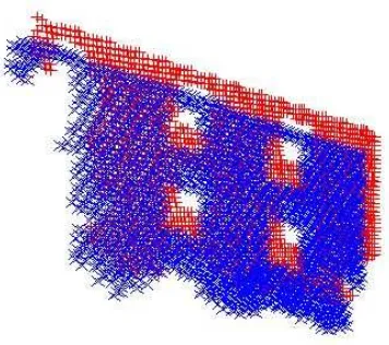
High-end mobile mapping systems integrate several laser scan-ners and several individual cameras or 360◦cameras. A mobile mapping campaign may include several overlapping areas, lead-ing to overlapplead-ing point clouds. Partial or total GNSS occlu-sions, or multipath, may occur, specially in urban areas. This causes an error to the platform or vehicle trajectory determina-tion. Other sources of error can be Inertial Measurement Unit (IMU) modelling errors and eventually system calibration errors. All these errors produce that overlapping point clouds are not properly registered (Figure 1). To solve this, a laser-laser regis-tration must be performed. Also, some applications might require having coloured point clouds. Then, the coloured point cloud is usually derived from another registration process between camera and laser scanner.
The standard procedure for laser-to-laser and camera-to-laser co-registration includes several steps. The first ones are the system calibration where the lever arm and boresight between laser and IMU, and between camera and IMU must be determined. With current INS, GNSS and image matching technologies, the best results are obtained with the well known Integrated Sensor Orien-tation (ISO) method. In ISO, tie points measurements are used in combination with ground and platform control observation. The ISO method has been proven to be feasible and efficient for IMU-camera boresight calibration of mobile mapping systems
(Kerst-ing et al., 2012). For aerial laser and mobile mapp(Kerst-ing data, ISO has also been proven to be effective for the IMU-laser boresight calibration with single and multiple laser scanners (Skaloud and Lichti, 2006), (Chan et al., 2013).
After the calibration steps, a camera and LiDAR point cloud can be derived. Then, a co-registration between LIDAR points clouds and between camera point cloud and LiDAR point cloud are com-puted. Alternatively the LiDAR point cloud can be projected onto 2D image space, and then several image-to-image registration al-gorithms can be applied. The Iterative Closest Point algorithm (ICP ) (Chen and Medioni, 1992), is widely used for registration of point clouds, enabling many improved variants (Nov´ak and Schindler, 2013).
The ICP has been used for registration of pairs of point clouds generated from laser, from pairs of overlapping images, or a com-bination of them. The ICP has been proven to be effective with point clouds that were initially aligned (Nov´ak and Schindler, 2013). (Gressin et al., 2012) propose a method where uses ICP as initial step for trajectory improvement. The overall registration is performed improving the original platform trajectory. (Elseberg et al., 2013) deals also with laser-to-laser registration by improv-ing the platform trajectory. The trajectory is improved usimprov-ing a semi-rigid Simultaneous Localization and Mapping.
In contrast to the standard approach, in this paper we propose to solve the orientation and calibration of laser and camera data in a single, combined adjustment. Solving the orientation and calibra-tion allows us to implicitly deal with the co-registracalibra-tion problem, because in our approach, we do not model the error symptoms but the error sources. The proposed method is based on the identifi-cation of common tie features between images and point clouds and their use in a combined adjustment. This common tie features are straight line segments.
Figure 1: Point cloud of 2 different strips from overlapping area
features, allows us to avoid point cloud based camera to LiDAR registration. In addition, the redundancy of the adjustment is in-creased and the geometry improved by means of including pho-togrammetric data into a LiDAR adjustment. The overall accu-racy can also be improved adding photogrammetric and LiDAR ground control information.
The paper is organized as follows. Firstly, the main ideas behind the simultaneous network adjustment are introduced. Then, the proposed models as well as some mathematical concepts behind the use of tie lines are explained in detail. The concept validation section presents the preliminary results of an adjustment obtained with real data. The last section summarizes the conclusions of the proposed approach and discusses future improvements.
2 PROPOSED APPROACH
We propose a method where camera, laser and camera-laser ISO are performed in a single, combined adjustment. In it, the imag-ing observations are image coordinates measured on camera data (the digital camera images) and selected measurements of the laser images (ranges and scan-angles). The other observations are surveyed ground control points and platform time-Position-Attitude (tPA). In state-of-the-art mobile mapping systems, the tPA is previously estimated using INS, GNSS and odometer ob-servations using a Kalman Filter approach. Ground control points can be used to derive indirect control observations like ground control lines and planes. The tie features are points (camera ISO), planar surfaces (laser ISO) and straight line segments (camera-laser ISO). Points, planes and lines are defined by 3, 3 and 4 independent parameters, respectively.
The classical camera ISO approach is well known. From the ob-servations mentioned above, estimates for the tie points (TP), for the exterior orientation parameters of the camera images (EO), for the self-calibration parameters of the camera, for the tPA shifts and possibly for other system calibration parameters are com-puted. In laser ISO, the unknown parameters of the tie planar bounded surfaces —tie planes (TPL)— are estimated together with tPA shifts, laser self-calibration parameters and possibly o-ther system calibration parameters.
In the proposed camera-laser ISO method, as mentioned, straight line segments —Tie Lines (TL)— are used as tie features be-tween camera and laser images. TLs tie camera and laser images as follows. Assume thatsis a TL that can be recognized in the
camera imagecand in the point cloud of a laser imagea, and also assume thatsis the intersection of two planar surfacesp1,p2
de-termined by points of the laser imagea. Givens,c,a,p1andp2
we will then use three types of observation equations. The first type of observation equation (a coplanarity equation) relates im-age measurements of thesTL on theccamera image withsTL parameters, with the EO and self-calibration parameters ofc. At least two of these observation equations are needed. The second type of observation equation (a line-in-plane relationship) com-pelssto lie on planes. In general, there will be two observation equations of this type, forp1andp2, although it is also possible to
use just one TPL. The third type of observation equation relates TPLs —in this casep1andp2— to the measured laser points, i.e.,
relate the laser range and scan-angle measurements, to the laser self-calibration parameters, the derived tPA, the tPA shift param-eters and possibly other system calibration ones. There will be, for eachp1 andp2, as many of these observation equations as
laser points that define the plane. Details of the models are given in the next section.
In our combined camera-laser ISO concept, laser raw data instead of processed point clouds are used. 3D coordinates of point-cloud points are not explicitly computed: the laser points that define the TPLs are parameterized with raw range and scan-angle mea-surements. This is a key aspect of the concept as it allows for self-calibration of laser measurements and system calibration re-finement. Our approach include also a platform trajectory shift to model trajectory errors due to GNSS occlusions, multipath or in-ertial noise and drift. Self-calibration of camera and laser image observations, system calibration refinement and trajectory error improvement, are the key to correct and consistent results. A dif-ferential characteristic of the combined camera-laser ISO concept is that can be used with camera and laser data acquired in different period of time and even with independent acquisition platforms.
It is out of the scope of this paper to discuss the measuring (TLs, TPs and TPLs extraction) and matching techniques that precede the ISO network adjustment stage. We summarize them for the sake of completeness. TLs are extracted from camera images by combining edge detectors and the Hough transform (Vossel-man et al., 2004). Once they are extracted, a matching proce-dure is performed to identify homologous TLs in different im-ages. TPs are extracted and matched from camera images us-ing a BRISK operator (Leutenegger et al., 2011). The outliers are filtered then, using relative orientation between photographs, derived from platform trajectory. In the laser ISO case, in this research, only planar surfaces, belonging to building walls and street pavement, are extracted. For the purpose, a region growing algorithm has been used.
3 MATHEMATICAL MODELS
The mathematical models needed to perform a single, combined camera-laser ISO were introduced for the first time in (Angelats et al., 2012). In this paper, airborne laser scanner and photogram-metric camera data were simultaneously adjusted using straight lines as tie segments. In order to expand this concept to mo-bile mapping systems, the presented models are still valid without modifications except for the MMS plane observations equations. In this section, we present in detail this model and the remaining models are briefly introduced. The interested reader may refer to (Angelats et al., 2012) for extended details of the mathematical modelling.
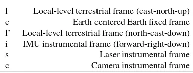
l Local-level terrestrial frame (east-north-up) e Earth centered Earth fixed frame l’ Local-level terrestrial frame (north-east-down) i IMU instrumental frame (forward-right-down)
s Laser instrumental frame
c Camera instrumental frame
Table 1: Reference frames and coordinate systems.
3.1 Some naming and notation conventions
The Coordinate Reference Frames (CRFs) involved in the math-ematical functional models of the paper are detailed in Table 1. The CRFlof a variableX is denoted by a superscript symbol likeXl. For a rotation matrixRbl, the subscript indicates the ori-gin CRF while the superscript indicates the final CRF so it can be writtenXl=Rl
bXb. For the sake of simplicity,X~e= (x, y, z)e is used instead of the formally correctX~e= [(x, y, z)e]T
.
3.2 Camera point collinearity observation equations
In camera ISO, the known collinearity observation equations are used to relate the camera image coordinate observations with the EO, tie point and self-calibration parameters.
3.3 MMS plane observation equation
The model extends the one proposed by (Angelats et al., 2012) to be used in mobile mapping systems. The observations are the two MMS laser measurements (range and scan-angle) and the tPA (position and attitude) ones. The MMS plane observation equa-tion is
The model includes an additional scale factor self-calibration pa-rameter for the scan-angle observation because our experience reveals its significance. The Hessian form of a plane is used to parametrize the planar surface. The plane is then characterized by a unit normal vector~nl = (n
x, ny, nz)l(equation 5) andd, the orthogonal distance between the plane and the CRF origin.λ0
andφ0are auxiliary vectors that brings an orthogonal vector~nl0
close to the nominal normal vector. Then, the parameters of the plane are the orthogonal distancedand two rotation anglesδl,δp. These rotation angles use to be quite small by construction.
The model have additional parameters to model tPA errors. These parameters are tPA position and orientation linear shifts. Table 2 summarizes the mathematical symbols of equations 1 to 5.
3.4 3D straight line parameterization
Straight lines are elementary mathematical objects with many possible parameterizations. We propose yet another one which is convenient for numerical computations and whose four universal parameters(p, q, α, β)can be used regardless of the line location and direction.
∆θ MMS scan-angle shift
Sθ MMS scan-angle scale factor
δl, δp, d tie plane
l′toeCRFs, respectively
R(λ0, φ0) auxiliary rotation matrix
~
nl0 = (0,0,1)
l
unit normal vector of tie plane
~ Pl
0= (P0x, P0y, P0z)l local origin coordinates for tie plane.
Table 2: Symbols in the MMS plane observation equation.
3.5 FC line coplanarity observation equation
This model relates the parameters(p, q, α, β)of a 3D line, the EO parameters of an image, and the image observations(x, y)
of a point of the line. It has been derived from the collinearity condition and the 3D straight line parameterization.
3.6 Line-in-plane observation equations
This model relates lines and planes in a 3D space. From a geo-metrical point of view, a line belongs to plane if two conditions are satisfied. The first condition is related to the orthogonality, that is, plane’s normal vector and line’s director vector must be orthogonal. The second condition is related to the distance be-tween line and plane. This distance must be 0 and it is equivalent that the line’s point belongs also to the plane.
4 CONCEPT VALIDATION
The proposed concept was tested and validated using real data from a high-end mobile mapping system. The data originate from a mobile mapping campaign over a controlled area of Dortmund (Germany). The mobile mapping system was an Optech Lynx system, from TopScan GmbH, that includes two laser scanner and two cameras. As for the software, an experimental “model tool-box” with the models discussed before was developed at CTTC that runs on the generic network adjustment platform GENA (Colomina et al., 2012).
computed, using a tightly coupled approach, combining differen-tial GNSS, IMU and odometer measurements. The points clouds, for both laser scanners within the same strip, and also between strips, where not co-registered. Photographs for each of the cam-eras, were also acquired. The platform trajectory was also used to provide an initial orientation of the photographs. The camera was previously calibrated and the lens distortion was removed from the photographs.
Since the aim of this paper is not an exhaustive study, a small subset of the original data has been used to validate the feasibil-ity of the one step orientation and calibration of laser and camera data from mobile mapping systems. For that reason, only data from one laser scanner and one camera have been used. The main characteristics of the camera and laser scanner systems as well as the test configurations are detailed in Table 3. The precision of the observations can be found in Table 4. Notice that from the camera derived data, 4 tie lines have been extracted. These tie lines correspond to some straight elements located on building walls such as cables, window edges, i.e. On the other hand, from the MMS-derived data, 12 planes have been used. 11 of them are present in 3 strips while the remaining plane only in 1. 4 planes of the first strip are used as a ground control planes while the remaining planes are used as a tie planes. Tie planes are verti-cal planes, corresponding to building walls, or horizontal planes, corresponding to street pavement. In this paper, the straight lines used as a common feature, belong to the tie planes, but are not breaklines, that is, the ones resulting from intersection of two tie planes.
With the given data, the configurations described in Table 5 have been processed. Block configuration cam TP performs a classi-cal camera ISO using all available tie points and a ground control point (GCPs) and EOs. Test cam TL adds 4 straight lines as tie lines. This configuration allows to validate the coplanarity equa-tion model with tie lines. As for the MMS tests, an MMS orienta-tion and calibraorienta-tion adjustment without camera data is performed using planes as tie features with four ground control planes (GC-PLs). The ALL configuration combines camera data with MMS data using tie points, ground control point for the camera ISO, tie planes and ground control planes for the MMS ISO and tie lines for the camera-ALS ISO. This test allows to test simultaneously all developed models.
The EO parameters are estimated for all proposed test. The pro-posed approach includes additional parameters, such as a tPA shift, corrections in the boresight matrix between the IMU and the camera (Table 6) and self-calibration parameters. However, in this preliminary study, they are not estimated due to the small number of photographs and a weak camera geometry, with only photographs from one strip and parallel to the vehicle movement direction.
For the MMS subblock, a tPA shift for each strip, can be esti-mated. Vertical tie planes allow to estimate the e,n component while using horizontal planes allow to estimate the h component. Self-calibration parameters of the MMS, that is∆r,∆θandS, cannot be estimated, neither the boresight matrix between IMU and laser scanner. These parameters cannot be estimated because they are strongly correlated between them and the geometry of the sub-block does not allow to decorrelate them.
The test results are shown in Table 7 and Table 8. As it was ex-pected, due to the small data set and GCP configuration, cam TP and cam TL results show a similar performance in terms of pre-cision (Table 7) for the EO parameters and tie points.
Camera sub-block
Equipment Optech Lynx camera
Applanix POS LV420
Image size 5.684 x 4.326 mm
Pixel size 3.5µm
Camera constant (f) 3.866 mm
No. of strips 1
No. of images 4
No. of ground control points (GCPs) 1
No. of tie points (TPs) 37
No. of tie lines (TLs) 4
Horizontal Overlap≈ 60%
MMS sub-block
Equipment Optech Lynx laser
Applanix POS LV420 Density (points/m2
) (≈) NA
No. of strips 3
No. of control planes (GCPLs) 4
No. of tie planes (TPLs) 12
Average no. of points per plane 1700
No. of tie lines (TLs) 2
Table 3: Dortmund block geometric configuration.
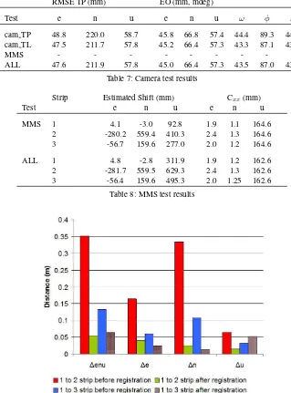
The result of tests case ALL shows that the simultaneous block adjustment works, although this resultin terms of precision is in-conclusive given the small differences and the small size of the experiment. The results indicate that it is possible to estimate a tPA shift for each strip (Table 8), for MMS and ALL tests. From the results, it can be observed that the h component has a higher
Cxxthan e,n component. This result was expected because more vertical planes than horizontal ones were used as tie planes.
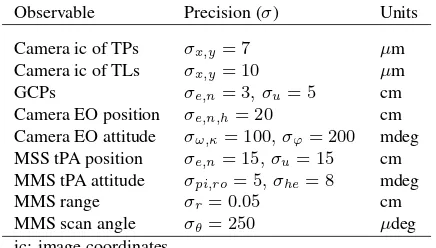
Observable Precision (σ) Units
Camera ic of TPs σx,y= 7 µm
Camera ic of TLs σx,y= 10 µm
GCPs σe,n= 3, σu= 5 cm
Camera EO position σe,n,h= 20 cm Camera EO attitude σω,κ= 100, σϕ= 200 mdeg MSS tPA position σe,n= 15, σu= 15 cm MMS tPA attitude σpi,ro= 5, σhe= 8 mdeg
MMS range σr= 0.05 cm
MMS scan angle σθ= 250 µdeg
ic: image coordinates
Table 4: Precision of the observations.
this SW, only to show the potential of the approach and give a coarse point cloud difference. Further research must be done to compute accurately the distance between point clouds, eventually leading to better results.
5 CONCLUSIONS AND FURTHER RESEARCH
A method where camera and MMS ISO were performed in one step by using straight as tie features, has been presented. It consist on a combined adjustment where points (camera), planes (MMS) and lines (camera-MMS) are used as a tie features. The mathe-matical models: 3D straight line parameterization, a coplanarity observation equation and a line-belongs-to-plane, presented in (Angelats et al., 2012) has been proved to be effective, with real data from a high-end mobile mapping system. A new MMS model has been successfully developed and tested. In the MMS model, laser raw measurements are used to allow for system and sensor calibration. In addition, includes also a tPA shift to model platform tPA errors due to GNSS occlusions, multipath.
The results of this paper are only preliminary because of the small size of the data sets. Photogrammetry results show that with this combined camera, MMS, and camera-MMS, concept, the perfor-mance in terms of precision, is at least maintained. The results suggest also that the platform trajectory can be improved with a linear shift. With this trajectory improvement, the co-registration between overlapping point clouds, is improved. The MMS self-calibration has not been performed due to a weak geometry and a small data-set. Further research must be done to explore how the combination with photogrammetric data can benefit the MMS the system calibration, and so, the co-registration.
With this approach, a single or several camera and laser data from different systems or from the same system with different acqui-sition, can be integrated and so, co-registered. The next step is to validate the presented concept and models with larger data sets and to understand the behavior of camera and MMS self-calibration parameters in combined adjustments. For larger data sets, alternative models than a linear shift to tPA correction, must be explored. Additionally, not only the precision, but also the accuracy of the one step approach must be measured. Further re-search must be done to explore the number of required ground control points and planes, since the previous experience suggest that the combined adjustment could reduce the required ground control information.
ACKNOWLEDGEMENTS
The research reported in this paper was funded by the INNPACTO subprogramme (Ministry of Economy and Competitiveness, Spain) within the ATENEA+ project, led by Deimos Space S.L.U (Spain). The authors thank TopScan GmbH (Germany) for pro-viding the Dortmund dataset, Optech Inc. (Canada) for propro-viding laser raw measurements and GeoNumerics S.L (Spain) for mak-ing its generic network adjustment platform GENA available. A special mention to Dr. Marta Bl´azquez for her support and tech-nical discussions.
REFERENCES
Angelats, E., Bl´azquez, M. and Colomina, I., 2012. Simultaneous orientation and calibration of images and laser point clouds with straight segments. In: International Archives of Photogrammetry, Remote Sensing and Spatial Information Sciences, Vol. 39(B1), Melbourne, Australia, pp. 91–96.
Chan, T. O., Lichti, D. and Glennie, C. L., 2013. Multi-feature based boresight self-calibration of a terrestrial mobile mapping system. ISPRS Journal of Photogrammetry & Remote Sensing 82, pp. 112–124.
Chen, Y. and Medioni, G., 1992. Object modelling by registration of multiple range images. Image and Vision Computing 10(3), pp. 145–155.
Colomina, I., Bl´azquez, M., Navarro, J. A. and Sastre, J., 2012. The need and keys for a new generation network adjustment soft-ware. In: International Archives of Photogrammetry, Remote Sensing and Spatial Information Sciences, Melbourne, Australia.
Elseberg, J., Borrmann, D. and N¨uchter, A., 2013. Algorithmic solutions for computing precise maximum likelihood 3d point clouds from mobile laser scanning platforms. Journal of Remote Sensing 5(11), pp. 5871–5906.
Giradeau-Montaut, D., Bougacha, S., Bey, A. and Marc, R., 2014. Cloudcompare SW, version 2.5.2, EDF R&D, Telecom ParisTech.
Gressin, A., Cannelle, B., Mallet, C. and Papelard, J., 2012. Trajectory-based registration of 3d lidar point clouds acquired with a mobile mapping system. In: International Archives of Photogrammetry, Remote Sensing and Spatial Information Sci-ences, Vol. 1-3, Melbourne, Australia, pp. 117–122.
Kersting, A., Habib, A. and Rau, J., 2012. New method for the calibration of multi-camera mobile mapping systems. In: Interna-tional Archives of Photogrammetry, Remote Sensing and Spatial Information Sciences, Melbourne, Australia.
Kutterer, H., 2010. Mobile mapping. In: Vosselman, G. and Maas, (Eds.), Airborne and Terrestrial Laser Scanning, first ed. Whittles Publishing, Dunbeath, Scotland, UK, pp. 293–311.
Leutenegger, S., M. Chili, M. and Siegwart, R., 2011. Brisk: Binary robust invariant scalable keypoints. In: Proceedings of the IEEE International Conference on Computer Vision (ICCV), Barcelona, Spain, 6-13 November, pp. 2548 – 2555.
Nov´ak, D. and Schindler, K., 2013. Approximate registration of point clouds with large scale differences. In: International Archives of Photogrammetry, Remote Sensing and Spatial Infor-mation Sciences, Vol. II-5/W2, Antalya, Turkey, pp. 211–216.
Skaloud, J. and Lichti, D., 2006. Rigorous approach to bore-sight self-calibration in airborne laser scanning. ISPRS Journal of Photogrammetry & Remote Sensing 61(1), pp. 47–59.
Test camera ic GCPs TPs camera TLs MMS rs TPLs GCPLs MMS TLs
cam TP YES 1 YES NO NO NO NO NO
cam TL YES 1 YES YES NO NO NO NO
MMS NO 0 NO NO YES YES YES NO
ALL YES 1 YES YES YES YES YES YES
ic: camera image coordinates. rs: MMS range and scan angle.
Table 5: Observations of block configurations.
camera MMS
Test EOs TPs BC Shift TLs (∆r,∆θ, Sθ) TPLs
cam TP YES YES NO NO NO NO NO
cam TL YES YES NO NO YES NO NO
MMS NO NO NO YES NO NO YES
ALL YES YES NO YES YES NO YES
BC: IMU-to-camera boresight matrix calibration. Shift: tPA linear shift.
Table 6: Estimated parameters of block configurations.
RMSE TP (mm) EO (mm, mdeg)
Test e n u e n u ω φ κ
cam TP 48.8 220.0 58.7 45.8 66.8 57.4 44.4 89.3 44.2
cam TL 47.5 211.7 57.8 45.2 66.4 57.3 43.3 87.1 43.4
MMS - - -
-ALL 47.6 211.9 57.8 45.0 66.4 57.3 43.5 87.0 43.2
Table 7: Camera test results
Strip Estimated Shift (mm) Cxx(mm)
Test e n u e n u
MMS 1 4.1 -3.0 92.8 1.9 1.1 164.6
2 -280.2 559.4 410.3 2.4 1.3 164.6
3 -56.7 159.6 277.0 2.0 1.2 164.6
ALL 1 4.8 -2.8 311.9 1.9 1.2 162.6
2 -281.7 559.5 629.3 2.4 1.3 162.6
3 -56.4 159.6 495.3 2.0 1.25 162.6
Table 8: MMS test results