Shear Response of Fibrous High Strength Concrete Beams without
Web Reinforcement
Sudheer Reddy, L.1, Ramana Rao, N.V.2, and Gunneswara Rao, T.D.3
Abstract: The use of steel fibers to improve the mechanical properties of concrete has been the ongoing interest in the research work. This paper deals with one such improvement in the mechanical property of concrete, which is the shear strength. In this paper an attempt has been made to study the improvement of shear strength of high strength concrete beams (70 MPa) with different shear span to depth ratios (a/d = 1, 2, 3, and 4) and various dosages of fibers (0.4%, 0.8%, and 1.2% by volume of concrete), without shear reinforcement. The experimental work revealed that steel fiber volume has different influence at different shear span to depth ratios (a/d). The test results indicated an increase in the cracking shear resistance noticeably and ultimate shear strength moderately.
Keywords: High-strength concrete, shear, steel fiber reinforced concrete, shear span to depth ratio (a/d).
Introduction
Cementitious material such as concrete has low tensile strength and fails in a brittle manner. The idea of using discrete, ductile fibers to reinforce concrete is not new with many studies having been undertaken over the past four decades. Early studies by Romualdi and Batson in 1963 [1] indicated that the tensile strength of concrete can be improved by providing suitably arranged and closely spaced wire reinforcement. The low tensile strength of concrete matrix is primarily due to the propagation of internal cracks and flaws. Romualdi and Batson hypothesized, that, if these flaws can be locally restrained from extending into the adjacent matrix, the initiation of tension cracking can be retarded and a higher tensile strength of the material can be achieved. Voo and Fostery [2] have put forth that the objectives of adding fibers to concrete mix is to bridge discrete cracks, to provide some control to the fracture process, and to increase the fracture energy.
Steel fiber reinforced concrete (SFRC) is a composite material with significantly better tensile strength
1
Faculty of Civil Engineering, Kakatiya Institute of Technology, Warangal – 506 015, Andhra Pradesh, INDIA.
Email: [email protected]
2 Faculty of Civil Engineering, Jawaharlal Nehru Technological
University,Hyderabad – 500 085, Andhra Pradesh. INDIA.
3 Faculty of Civil Engineering, National Institute of Technology,
Warangal – 506 001, Andhra Pradesh, INDIA.
Note: Discussion is expected before June, 1st 2011, and will be
published in the “Civil Engineering Dimension” volume 13, number 2, September 2011.
Received 18 May 2010; revised 20 August 2010; accepted 22 December 2010
and higher resistant to crack formation and propagation. This ability avoids the brittle failure mode. Research studies by Gunneswara Rao et al [3] revealed that SFRC is being used for improving cracking characteristics of reinforced concrete. Shear behavior and ultimate shear strength of reinforced concrete beams had been studied for last few decades. Former suggestions were based on the cube strength of concrete, which is still the main parameter in shear design principles of many countries. Research on the high strength concrete showed that the cube compressive strength has less significance than the fracture energy for the description of the material behavior of structural elements.
Remmel[4] was one of the first who tried to give an
Experimental Programme
To assess the response of high strength concrete (HSC) beams under shear loading, the following studies were carried out.
• Response of non fibrous concrete beams without
shear reinforcement, with shear span to depth ratio (a/d) from one to four.
• Behavior of steel fibrous concrete beams without
shear reinforcement, with a/d ratio from one to four and with volume fractions of fiber as 0.4%, 0.8%, and 1.2% of volume of concrete.
The experimental programme consisted of testing beams under shear loading in two series. The first series involved testing of four non fibrous HSC beams, without shear reinforcement, varying a/d ratio as one, two, three, and four. The second series involved testing of twelve fibrous HSC beams without shear reinforcement with a/d equal to one, two, three, and four and fiber content of 0.4%, 0.8%, and 1.2% of volume of concrete. For both series, the parameters viz., designed concrete proportions, aspect ratio of fibers and percentage of longitudinal reinforcement were kept constant. The details are listed in Table 1.
Materials Used
The physical and mechanical properties of constituent materials of HSFRC viz, cement, fine aggregate, coarse aggregate, steel fibers and longitudinal reinforcement are listed in Table 2.
Naphthalene based super plasticizer Conplast337 was utilized for improving the workability of the fibrous concrete. Pozzolonas such as, fly ash (Class F) acquired from Kothagudam Thermal Power Station and Ground Granulated Blast Furnace Slag (GGBS) with physical requirements confirming to IS 12089 1987 [10] procured from Vizag were utilized.
Table 1. Reinforced HSC and HSFRC beams without
shear reinforcement Sl. fraction of
fibers
Reinforcement and Steel Fibers 0.41: ‘0.4’ indicate 0.4% Fibers. ‘1’ indicate a/d Ratio.
Mix Design:
The high strength concrete mix design has been prepared using Erntroy and Shacklock method [11], concrete mix design optimized approach proposed by Ilinoiu [12] and expert system for design of high performance concrete by Fauzi et al [13]. The details of the ingredients of high strength concrete are presented in Table.3.
Specimen Details:
Tests were carried out on sixteen beams which were simply supported under two point loading. All beams had constant cross section of 100 mm x 150 mm. For each variation of fiber content (0%, 0.4%, 0.8%, and 1.2%) shear span to depth ratio was varied as one, two, three, and four. The length of beams were worked out to be 0.7 m, 1.0 m, 1.2 m, and 1.6 m for corresponding a/d ratios of one, two, three, and four respectively. The ‘R’ series of beams (four numbers of reinforced HSC) and ‘FR’ series of beams (twelve numbers of HSFRC with fiber content 0.4%, 0.8%, and 1.2%) were provided with three 20 mm diameter high yield strength deformed bars as longitudinal reinforcement as illustrated in Figure 1.
Table 2. Properties of materials used:
Material Properties Cement Specific Gravity
Fineness
28- day Compressive Strength
3.10 5% 55 MPa Fine Aggregate Specific gravity
Fineness modulus
2.63 2.33 Coarse Aggregate Specific gravity
Maximum size in mm 2.64 20 Steel Fibers(rounded
Straight)
Aspect ratio Yield Strength
75 550 MPa Main bars 20 mm
Diameter
Yield Strength 475 MPa
Table 3. Mix Proportion of Concrete Cement
Test Procedure
The beams were tested on loading frame of 100 ton capacity. Ends of the beam were simply supported and load was transferred through a rigid spread beam on to the test specimen. Based on the a/d ratio, supports of the spread beam were adjusted so as to vary the shear span to depth ratio (as depth of the beam was constant for all beams tested) from one to four. Two LVDT’s were used to monitor the deflections at the mid span and at the centre of the shear span. The bend over point in the load displacement diagram of the beam was taken as cracking load and the test was carried out till the load in post peak region reaches 70% of the ultimate load. Crack patterns were marked on the beam. The test set up is presented in Figures 2 and 3.
Results and Discussion
The load–displacement variation of the tested beams are presented in Figures 4 to 7. From these variations, it is clear that the load deflection variation is linear approximately up to 68% of the ultimate load. The load resistance in the post cracking region is due to longitudinal reinforcement alone and the variation is approximately linear. During the post cracking and pre-ultimate stage a number of secondary cracks have appeared in the shear zone.
RCC Beam
Spread Beam
Shear Span Shear Span
100 Ton Jack
Load Cell
LVDT
Figure 2. Arrangement of test specimen
Figure 3. 100 ton loading frame-Arrangement of test
specimen
Beyond the ultimate load, the load bearing capacity of the member decreased and the widening of a single potential crack in the shear span leads to the ultimate failure. In case of fibrous beams, the post ultimate deflections are found to be more than that of the non fibrous beams. This clearly indicates that the addition of fiber enhances the post ultimate ductility of the members.
In the entire load–displacement variations of the
tested beams, the increase in shear capacity is
remarkable up to 0.8% dosage of fibers but decreased slightly at 1.2% dosage of fibers. This decrease in shear capacity for 1.2% fiber content may be due to less workability observed during casting. The area under the load deflection curve which is a measure of energy absorbed by the test specimen is found to be higher for fibrous beams compared to non fibrous beams. The increasing trend in energy absorption capacity is observed with the increase in volume fraction of fibers. The increase in energy absorption capacity is found to be 27% for a/d equal to one and two and 40% for a/d of three and four. Lower energy absorption for lower a/d ratios (one and two) may be attributed to the strut and arch action in the beam. In strut action, failure of the beam is governed by the compressive strength of concrete present in the strut. As the fiber is poor in increasing the compressive strength of the concrete, the energy absorption for strut action is found to be low. For higher a/d ratios (three and four), beam action prevails and the load carrying capacity is governed by the diagonal tensile strength of concrete.
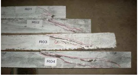
The failure pattern of the beams shown in Figures 8-11 clearly indicate that for a/d equal to one and two crack initiated approximately at 45 degrees to the longitudinal axis of the beam. A compression failure finally occurred adjacent to the load which may be designated as a shear compression failure. For a/d of three and four the diagonal crack was formed joining the loading point and the supporting point under the shear loading.
0 50 100 150 200 250 300 350 400
0 10 20 30 40
Deflection (mm)
Lo
a
d
(
k
N
)
R01
FR0.41
FR0.81
FR1.21
The diagonal crack formed in shear region moved up into the zone of compression and became flatter. The failure may be designated as diagonal tension failure. The pattern of potential crack of HSFRC beams (FR Series) is similar to that of HSC (R series) beams.
Steel fibers are effective in improving the tensile behavior of the HSFRC beams in terms of deformation, cracking strength and energy absorption. The failure of the beams at lower a/d ratios was observed to be diagonal compression failure. Therefore the inclusion of fibers has improved deformation, cracking strength and energy absorption moderately for a/d equal to one and two.
0 50 100 150 200 250 300 350
0 10 20 30 40
Deflection (mm)
Loa
d (
k
N
)
R02 FR0.42
FR1.22 FR0.82
Figure 5. Load-Deflection relation for a/d = 2, with 0%, 0.4%, 0.8% and 1.2% fibers in HSC Beams.
0 50 100 150 200 250 300 350
0 10 20 30 40
Deflection (mm)
Lo
a
d
(
k
N
)
R03 FR0.43 FR0.83
FR1.23
Figure 6. Load - Deflection relation for a/d = 3, with 0%, 0.4%, 0.8% and 1.2% fibers in HSC Beams.
0 50 100 150 200 250 300 350
0 10 20 30 40
Deflection (mm)
Lo
a
d (
k
N
)
R04 FR0.44 FR0.84
FR1.24
Figure 7. Load - Deflection relation for a/d = 4, with 0%, 0.4%, 0.8% and 1.2% fibers in HSC Beams.
Figure 8. Cracking patterns HSC beams with 0% fibers for a/d =1, 2, 3 and 4
Figure 9. Cracking patterns HSFRC beams with 0.4%
fibers for a/d =1, 2, 3 and 4
Figure 10. Cracking patterns HSFRC beams with 0.8%
fibers for a/d =1, 2, 3 and 4
Figure 11. Cracking patterns HSFRC beams with 1.2%
The failure mode in higher a/d ratios was observed to be diagonal tension type. Therefore the increase in volume fraction of the fiber has shown a better improvement in HSFRC beams for a/d ratios of three and four. From this discussion it can be inferred that, the addition of fibers in the region where diagonal tension is predominant in HSC beams may be more effective.
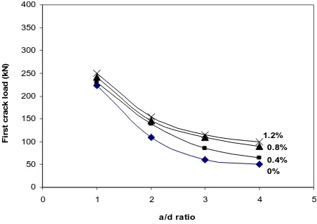
The values of first crack load and ultimate crack load for a/d equal to one, two, three and four with 0%, 0.4%, 0.8%, and 1.2% fibers are presented in Table. 4. A comparison of first crack load of different beams tested in this investigation is presented in Figure 12. It can be observed that the first crack load increased with the increase in dosage of fibers. The rate of increase in ultimate as well as cracking is remarkable from 0 to 0.4% and 0.4% to 0.8% fibers. The rate of increase is nominal at 1.2% dosage of fibers. This reduction in the improvement of cracking load with the increase in fiber dosage beyond 0.8% may be attributed to the fact that the higher fiber content adversely affects the workability (balling effect) and reduces the uniformity of the matrix, decreasing the increase in the tensile strength of the matrix. Thus the optimum dosage of fibers may be considered as 0.8%.
Figure 13 gives the variation of ultimate load capacity of the members with increase in a/d ratio. It is observed that, there is a drastic reduction in the ultimate strength of the beam for a/d ratios of one to two, as the failure type is strut or shear compression type. The reduction in the ultimate strength beyond a/d ratio of two is less, as the failure type for this a/d ratio is diagonal tension type failure. Thus, it is rational to incorporate the a/d ratio in estimating the ultimate as well as cracking shear strength of HSC beams with and without fibers under shear loading.
Table 4. First crack load and failure load of the specimens S. No Beam
Designation
First Crack Load (kN)
Ultimate Load (kN)
Figure 12. Variation of first crack load and a/d ratio for volume fraction of fibers 0%, 0.4%, 0.8%, and 1.2%.
0
Figure 13. Variation of crack load and a/d ratio for volume fraction of fibers 0%, 0.4%, 0.8%, and 1.2%.
Table 5. Split tensile strength of cylinders for varying volume fraction of fibers.
Sl.No Vf (%)
Split Tensile strength (MPa)
Non- Dimensionalised tensile strength
1 0 2.85 1.00
2 0.4 3.59 1.26
3 0.8 4.10 1.44
4 1.2 4.20 1.47
5 1.6 4.20 1.47
Figure 14. Variation of Tensile Strength (Dimension Less) with volume fraction of fibers (Vf - 0%, 0.4%, 0.8%,1.2%,
and 1.6%).
The non dimensional Tensile strength is given by
(0.371 1)
ft-R = Split tensile strength of Normal concrete in MPa
Vf = Percentage volume fraction of fibers.
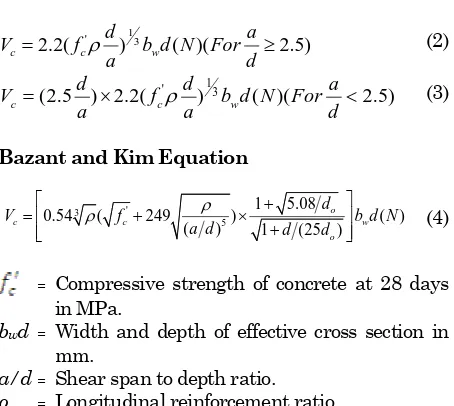
Zsutty [17] and Bazant and Kim [18] have formulated the equations for predicting shear strength of concrete members without web reinforcement:
Zsutty Equation
1
Bazant and Kim Equation
'
= Compressive strength of concrete at 28 days
in MPa.
bwd = Width and depth of effective cross section in
mm.
a/d = Shear span to depth ratio.
ρ = Longitudinal reinforcement ratio.
The Equations 2, 3, and 4, which predict the shear strength of both shorter and longer beams, take into account the parameters: a/d ratio, longitudinal reinforcement ratio and tensile strength of concrete. These parameters are combined into a single parameter and are hereafter referred as shear influencing parameter (SIP). Shear span to depth ratio governs the failure pattern of the beam. Tensile capacity governs the diagonal cracking strength of the beam while the longitudinal reinforcement influences the shear capacity of the beam through
dowel action. Thus the shear influencing parameter factor (SIP) is taken as:
SIP = f ρ
ρ = Longitudinal Reinforcement Ratio.
To study the shear capacity of HSC and HSFRC beams without shear reinforcement, the parameters tensile strength of concrete, shear span to depth ratio (a/d) and tensile reinforcement ratio were taken into account in terms SIP. The variation of ultimate shear strength of the beams with SIP is presented in Figure 15. The linear regression analysis between the shear strength and SIP is formulated as Equation 6, which quantifies the shear capacity of HSC and HSFRC beams without shear reinforcement.
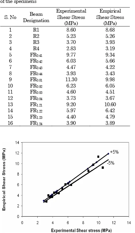
The empirical shear stress values calculated from the Equation 7 and the experimental shear stress values for HSC and HSFRC beams for a/d ratio of one, two, three and four with volume fraction of fibers (0%, 0.4%, 0.8%, and 1.2%) are listed in Table 6. From Figure 16, it can be understood that the experimental and empirical values are in a cluster, which indicates that, the estimation of shear capacity of the beam is quite fair.
t = 29.106(SIP)0.6971
0.00 0.05 0.10 0.15 0.20 0.25 0.30
SIP
Table 6. Experimental and Empirical shear stress (MPa) of the specimens
S. No Beam Designation
Experimental Shear Stress
(MPa)
Empirical Shear Stress
(MPa)
1 R1 8.60 8.68
2 R2 5.23 5.26
3 R3 3.70 3.93
4 R4 2.83 3.19
5 FR0.41 9.77 9.34
6 FR0.42 6.03 5.66
7 FR0.43 4.47 4.22
8 FR0.44 3.93 3.43
9 FR0.81 11.30 9.98
10 FR0.82 6.23 6.05
11 FR0.83 4.60 4.51
12 FR0.84 3.73 3.67
13 FR1.21 9.20 10.60
14 FR1.22 5.97 6.42
15 FR1.23 4.40 4.79
16 FR1.24 3.90 3.89
Figure 16. Variation of shear stress–Experimental Values to Empirical values
The values fall within +5% and -5% variation lines. Thus the proposed equation can estimate the shear resistance of fiber reinforced concrete beams without stirrup reinforcement, under shear loading.
Conclusion
Based on the experimental studies conducted on HSC and HSFRC beams without web reinforcement under shear loading, the following conclusions have
been drawn:
• The proposed shear equation (Equation 6) fairly
quantifies the shear capacity of the beams under shear loading.
• The fiber influence on the first crack load and
the ultimate load of the fiber reinforced concrete elements is considerable at lower a/d ratios, i.e. at a/d less than two.
• At higher a/d ratios, the influence of fiber on
shear capacity of fiber reinforced elements is small.
• The energy absorption capacity of HSFRC
elements at all a/d ratios is high when compared with conventional non fibrous concrete beams.
• The experimental results revealed that for all
a/d ratios, for 0.8% volume fraction of fibers there is a maximum increase in shear capacity of beams.
References
1. Romualdi, J.P., and Batson, G.B., Behavior of
Reinforced Concrete Beams with Closely Spaced
Reinforcement, Journal of the American Concrete
Institute, Proceedings Vol. 60, No. 6, June 1963, pp. 775–789.
2. Voo, J.Y., Fostery, S.J., Variable Engagement
Model for the Design of Fiber Reinforced
Concrete Structures, ECI Conference on
Advanced Materials for Construction of Bridges,
Buildings and Other Structures III, Davos,
Switzerland, 2005.
3. Gunneswara Rao, T.D., Rama Seshu, D., and
Warnitchai, P., Effect of Steel Fibers on the Behavior of Over-Reinforced Beams Subjected to
Pure Torsion, Civil Engineering Dimension, Vol.
12, No. 1, 2010, pp. 44–51.
4. Remmel, G., Zum Zug- und Schubtragverhalten
von Bauteilen aus hochfestembeton. DafSb. Heft 444, Beuth Verlag Berlin, 1994.
5. Lin, W.T., Huang, R., Lee, C.L., and Hsu, H.M.,
Effect of Steel Fiber on the Mechanical Properties of Cement-based Composites
Containing Silica Fume, Journal of Marine
Science and Technology, Vol. 16, No. 3, 2008, pp. 214–221.
6. Imam, M., Vandewalle L., Mortelmans F., Shear
Capacity of Steel Fiber High Strength Concrete Beams, Katholieke Universiteit Leuven, 1997.
7. Bukhari, I. A., and Ahmed, S., Evaluation of
Shear Strength of High Strength Concrete
Beams without Stirrups, The Arabian Journal
for Science and Engineering, Vol. 33, No. 2B, October 2008, pp. 323–335.
8. Kim, J.K., and Park,Y.D., Prediction of Shear
Strength of Reinforced Beams without Web
Reinforcement, ACI Materials Journal, Vol. 93,
No. 3, May- Jun 1996, pp. 213–221.
9. Chandrasheker Rao, T.D., Gunneswara Rao and
Ramana Rao, N.V., An Appraisal of Shear
Journal of Civil Engineering, Vol. 7, No. 6, 2006, pp. 591–602.
10. IS 12089:1987, Indian Standard Code for
Specification for Granulated Slag for Manufacture of Portland Slag Cement.
11. Erntroy, H.C., and Shacklock, B.W., Design of
High Strength Concrete mixes, Proceedings of a
symposia on Mix Design and Quality Control of
Concrete, Cement and Concrete Association,
London, May 1954, pp. 55–65.
12. Ilinoiu, G., Concrete Mix Design Optimized
Approach, Civil Engineering Dimension, Vol. 6,
No. 1, 2004, pp. 49–56.
13. Fauzi, M., Islam, I., Basri, M.H., An Expert
System for Mix Design of High Performance
Concrete, Journal of Advances in Engineering
Software, Vol. 36, No. 5, May 2005, pp. 325–337.
14. Shah, S.P., New Reinforcing Materials in
Concrete Construction, ACI Journal Proceedings,
Vol. 71, No. 5, May 1974, pp. 257–262.
15. Shah, S.P., and Naaman, A.E., Mechanical
Properties of Steel and Glass fiber Reinforced
Concrete, ACI Journal Proceedings, Vol. 73,
No.1, Jan. 1976, pp. 50–53.
16. Ganesan, N., and Ramana Murthy, J.V., Studies
on Confined Steel Fiber Reinforced Concrete, The Indian Concrete Journal, November 1990.
17. Bazant, Z.P., and Kim, J. K., Size Effect in Shear
Failure of Longitudinally Reinforced Beams,
ACI Journal Proceedings, Volume 83, No. 2,
Mar- Apr. 1986, pp. 456–468.
18. Zsutty, T. C., Shear Strength Predictions for
Separate Categories of Simple Beam Tests, ACI