SOLIDIFICATION ANALYSIS OF BISMUTH BASED ALLOY
IN CONTINUOUS CASTING PROCESS
Barman Tambunan
Pusat Pengkajian dan Penerapan Teknologi Material P3TM – BPPT, Gedung BPPT II, Lantai 22
Jl. M.H. Thamrin No. 8 Jakarta 10340 Email: [email protected]
ABSTRACT
Continuous Casting is a manufacturing process for producing billets, slabs and flat products. It is used for casting non-ferrous and steel production to produce high quality products of slab or billet cast at reduced cost. A thin solidified metal shell is formed initially during continuous casting due to the intense cooling from the water cooled mould. Once the cast leaves the mould it goes through various cooling processes and in solid state will proceed to the further forming processes. To exploit the benefit of continuous casting process it is essential to develop close control of the production process. This is achieved through a good understanding of the influence of the various compositional and operational variables. The objective of the mathematical analysis presented here is to model the heat transfer during continuous casting of low melting point Bismuth alloy cast billets material for predicting the surface temperature. Good quality of the cast in conjunction with the surface quality of the cast is relied on the solidification temperature during continuous casting. In fact by simulating the solidification temperature of the continuous casting process through applying different operational casting parameters, the result are crucial for identifying the best operational casting parameters.
Keywords: Continuous Casting, Solidification, Enthalpy Method, Simulation
Makalah diterima 17 September 2005
1. INTRODUCTION
Continuous casting has been introduced to replace the discrete production of first solidified form of metal blocks so called ingots in a continuous manner, with subsequent rolling process. Various shapes such as blooms, billets or slabs are manufactured directly from the molten metal steel which produced by the electric arc furnace (EAF) or basic oxygen furnace (BOF) directly. Blooms are usually used to produce rails and heavy sections, billets are used for making bars, rods and wire; and slabs are produced for making flat products of various dimensions. Nowadays, continuous casting is the technique applied in the majority of steelmaking industries and
Thin solidified metal shell is formed due to the intense cooling from the water cooled mould. Inside the shell large molten core remain and solidify during the withdrawal of the strand. The operating conditions for the mould during casting are the most critical for the whole process for producing a crack-free surface cast. Several parameters controls the shell development in the mould such as the temperature of the incoming hot liquid material, the dimensions of the mould, the oscillating mould, mould lubrication, the cooling water flow rate and the speed of the solid strand. The quality of the slab casting production depends on the solidification phase during casting process. Therefore, by developing a mathematical heat transfer model of the solidification process, one may identify the optimal operational parameters during continuous casting to obtain a high quality slab.
In order to gain further insight into continuous casting it is important to understand the solidification process which is strongly influenced by the temperature and flow of molten metal. This can only be obtained by carefully study and pinpoint various operational casting parameters that can affect the quality of the continuous casting product. Most of theoretical modeling available (Takeuchi, et.al, 1991; Takeuchi and Brimacombe, 1984) have been compared either with data from a commercial production process using sophisticated equipment or using water flow to verify their analysis (Sheng and Jonnson, 2000). Economically, it is not feasible to obtain a wide range of data from an industrial continuous casting to build a better understanding of the process. To identify parameters that improve the process require changes in production parameters, addition of new sensors or measurement devices to a commercial casting process. This may cause interruption in production and inconveniences for the organization.
The present study is concerned with the review of mathematical model and development of numerical simulation of heat transfer solidification of the molten low melting point Bismuth alloy in order to predict the surface temperature of the billet cast product. Different operational casting
parameters have been considered during simulation to determine solidification temperature of the strand and to predict the shell thickness of the billet from the meniscus region throughout the mould exit in continuous casting process.
2. HEAT TRANSFER PROCESS IN
THE MOULD
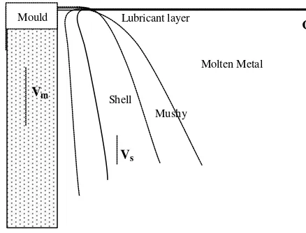
The first continuous casting analysis concerns the heat transfer solidification of the molten metal in the mould region. During operation of the casting various variable can influence the solidification of the product such as the incoming metal temperature, molten properties, mould geometry, mould lubricant and the mould cooling system. The formation of the casting shell is shown in Fig. 1. Vm is the mould oscillation speed, Vs
is the casting speed and CL is the centre line
of the mould geometry since the profile of the mould is always symmetry. As depicted in Fig. 1, the Meniscus zone where the shell begins to form the liquid metal is separated by the lubricant layers. Three different phases of metal cast exist in the mould zone during solidification process of the cast consists of solid, liquid and mushy zone (Huang, et.al., 1992; Shy, et.al., 1992). The mushy zone is the solid-liquid interface where part of the metal becomes solid and part of them is liquid. Casting factors such as heat extraction process accompanying by the solidification has shown an important role to perform a good quality cast product. The casting design and operational parameter during continuous casting at the meniscus mould region is important since the surface of the cast is initiated and built in this region (Mahapatra, et.al., 1991).
in steel continuous casting, the heat transfer at the flux channel constitutes the largest contribution to the heat extraction in the mould while the mould wall has the lowest contribution. Thus heat removal in the continuous casting mould is dependent largely to the gap between the solidified strand and the water cooled copper mould.
Figure 1. Physical System for initial solidification in continuous casting mould
The molten metal pool in steel continuous casting process is controlled by different heat transfer removal process such as heat in the liquid molten steel, latent heat of solidification in the mushy zone and heat conduction from the solid shell (Mizikar, 1967). On the last heat removal process heat is conducted away from the solidification boundary front to the cooler surface of the steel shell. At the front surface of the strand in the mould region heat is removed by the water cooled copper mould which picks up the heat to form the solidified skin shell on the outer surface of the cast material. Fig. 2 shows the heat transfer process in more details from the liquid pool to the surface of the mould.
Several operational casting parameters control the heat transfer and solidification process of the shell in the mould (Birat, et.al., 1991; Thomas, et.al., 1997). As shown here, the temperature in the mould decrease dramatically from the liquid pool measured above 1500 °C to less than 100 °C at the copper surface far from the
strand. Inside the mould liquid steel solidifies against mould surface controlled by the water cooling mechanism at the back of the surface of the mould. In addition casting speed and the geometry of the mould also influence the solidification process during the formation of the shell. The steel shell must be thick and strong enough to contain the molten steel during cast withdrawal.
Figure 2. Several heat transfer and temperature distribution in Continuous
Casting mould 4)
3. CONTIN UOUS CASTING
EXPERIMENTAL RIG
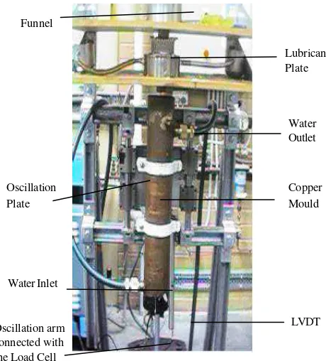
A new continuous casting experimental rig has been developed at Manufacturing Laboratory at RMIT University, Melbourne, Australia. In development of this continuous casting rig three criteria have been taken into account; firstly, the rig should represent the real situation. Secondly, the rig should be instrumented with a measurement system for obtaining the require data and thirdly, the continuous casting rig should be easy to operate and to control. Experiments can be readily undertaken using this continuous casting rig (shown in Fig. 3) without the limitations associated with disrupting industrial continuous casting operations or without costly plant trials.
Molten Metal
CL
Lubricant layer
Shell
x y
Vs
Vm
The continuous casting rig uses an oscillatory mould with variable oscillation speed and amplitude. During casting, the mould oscillates in the vertical direction with adjustable amplitudes of up to 20 mm. The function of mould oscillation with proper lubrication in continuous casting is to prevent sticking of the strand to the mould’s wall. Instead of using supported rolls to pull the solidify cast located underneath of the mould, a wire was connected to the dummy block and pulled down at a controllable speed. A motor driven-wire mechanism was used to withdraw the solidifying cast from the mould.
Water required for mould cooling is supplied continuously from the inlet channel at the bottom of the mould and exits through the outlet on the top of the mould. This water inlet and outlet system will deliver continuous cooling into the mould during casting. Water supplied into the system has an average temperature of 22 °C.
The billet mould was made from copper which is also used in industrial continuous casting moulds. The mould is tubular (1 mm thick) and cylindrical in shape; formed of two concentric cylinders. The inner diameter of the mould cylinder is
33 mm and the outer diameter is 74 mm and the length is 400 mm. These two cylinders were welded together at bases to form a space for water circulation in the mould and to produce adequate cooling for the molten metal to solidify.
3.1 Operation of the Experimental Rig
Bismuth based alloy called Wood’s metal was used as cast material. This metal replaces the high melting temperature casting material such as steel or aluminium. Wood’s metal has a low melting point temperature of 71°C which is ideal for the experimental rig. Wood’s metal can be continuously poured and withdrawn from the mould and mimics the characteristics of continuous casting of steel very well. For this reason, Wood’s metal was selected as cast material in this work.
The metal was heated in a furnace to 82 °C and let to cool at room temperature to just above its melting point and then poured into the mould. This melted material was introduced from the top of the mould through the available funnel. Underneath the funnel a lubricant plate was placed to lubricate the mould wall during casting.
4. THE MATHEMATICAL MODEL
OF THE HEAT TRANSFER
SOLIDIFICATION
Mathematical modelling for predicting the solidification front, heat transfer and the temperature distribution of the liquid steel pool in the mould region of a continuous casting process have been reported. Modelling of the top surface flux layers in continuous casting process has been indicated by McDavies and Thomas, 1996. The model has reported to include the thermal conductivity dependent temperature and the enthalpy variations over a range a temperature for analyzing the flux flow and thermal behaviour of the mould flux. Modelling of the liquid metal flow through bifurcated nozzles in continuous casting is reported by Najjar et al., 1995. Modelling of pouring temperature for investigating the superheat dissipation in steel continuous
Copper Mould Oscillation
Plate
Lubricant Plate
Water Outlet
LVDT Water Inlet
Funnel
Oscillation arm connected with the Load Cell
casting has been reported by Huang et al., 1992. Thomas et al., 1997 have investigated numerically the heat transfer and temperature distribution in the solidifying shell of steel slab using the 1-D transient heat conduction equation by assuming negligible axial heat conduction. Mizikar, 1967 described a mathematical model of heat transfer solidification in continuous casting mould and predicted the slab shell thickness during casting. His approach was to solve a 1-D unsteady state heat conduction equation by using an “artificially” high effective thermal conductivity and a “simplify” effective specific heat versus temperature relationship over a wide range of temperature up to the liquid region.
From Mizikar, 1967 analysis it is evident that he has assumed a constant value for the latent heat release in the mushy zone. In this work a constant value for the latent heat release in the mushy zone is applied to enhance more accurate prediction of the strand thickness in the mould region of continuous casting process.
4.1 Theory of Thermal Analysis
Due to the latent heat release during solidification the heat transfer equation is non-linear. The basic equation for two dimensional nonlinear heat conduction equations in an isotropic medium can be written in the form
(
( )
) ( ) ( )
q* the Laplace differential operator, cp(T)denotes the specific heat, T is the temperature which is a function of position and time, and k(T) is the thermal conductivity. Furthermore q* denotes the internal heat generated term involves the energy removed due to the latent heat of fusion during solidification in continuous casting process. The internal heat generated term q* is equal to zero everywhere except in the mushy region where the latent heat is released. As has been reported by many workers (Mizikar, 1967; Davies and Shin,
1980; Cliff and Dain, 1967) the density ρ(T)
is assumed constant in this analysis The density is less dependent on temperature including in the region where the phase transformation occur. The specific heat cp(T)
and the conductivity k(T) of bismuth alloy at a range of temperature from the liquid phase to the solid state are strongly varied. The temperature dependent thermophysical properties are the subject of further discussion in the next section.
When solidification is occurring, the associated latent heat L constitutes a heat source which is taken care by the internal heat generated term q*. This heat source term
q* as indicated by Laitinen and Neittaanmaki, 1988 can be obtained from the time rate of change of solid fraction fs during
solidification which is expressed as,
fusion and fs denotes the fraction of solid.
The fraction of solid fs = fs(T) describes how
the solid phase fraction varies with temperature T. The release of latent heat is difficult to describe mathematically because of the complexity of solidification in multi component alloy system. However, it was assumed in this model that no convective mass and energy transport in the liquid phase and mushy zone was considered. The liquids and the solidus temperatures were defined at an exact range of temperature to permit solidification process at the mushy region to be specified on the basis of point temperature.
4.2 The Solid Fraction Relationship
In order to solve Eq. (2) the fraction of solid fs and temperature T relationship
must be defined. In practice, the solid fraction fs versus temperature curve depend
solidify-cation it is assumed that that complete diffusion occur between the solid and liquid states during solidification. In non-equilibrium solidification the liquid is assumed to reach complete diffusion while diffusion in the solid state is negligible. The easiest way to descript this relationship is by assuming that latent heat is released linearly between the solidus and liquids temperature.
4.3 The Enthalpy Formulation
A popular variation for solving Eq. 1 with the latent heat release during solidification has been reported by Lally et al., 1999; Voller and Swaminathan, 1991; and Voller and Peng, 1994. They have suggested including the latent heat as an enthalpy source term and then considering the latent heat as a dependent variable which is known as the enthalpy method. By Eq. 1 and Eq. 2 we get the heat transfer model with the latent heat and fraction of solid variables,
( )
div(
k( )
T T)
The relationship between the enthalpy and temperature the is defined by
solid and liquid interface the total Enthalpy
H is determined as,
The heat transfer equation in terms of enthalpy after applying the chain rule to
?H/?t can be written as
by integration the specific heat while to determine the heat latent heat H2 the fraction
of solid and temperature relationship must be defined which has been described in previous section.
4.4 Material Property Data of Bismuth
Based Alloy Material
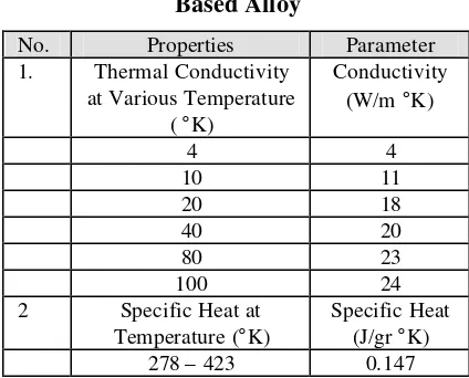
A low melting point Bismuth based alloy, called Wood’s metal (Handbook of Industrial Materials, 1992) was chosen as the casting material to suit our laboratory facilities. The melting point temperature of the Wood’s metal is 71 °C. During continuous casting Wood’s metal have successfully been used to cast a billet shape material. It was noticed that Wood’s metal satisfies the condition of a low melting point temperature of 71 °C. This is regarded as the proper material for conducting the experimental work. Properties of the bismuth based alloy are shown in Table 1 (Igor, et.al., 1997).
Tabel 1. Thermal Properties of Bismuth Based Alloy
No. Properties Parameter 1. Thermal Conductivity
at Various Temperature ( °K)
Specific Heat (J/gr °K) 278 – 423 0.147
The thermal conductivity of bismuth alloy in continuous casting is temperature dependent and its value varies according to the material composition and thermal history. Representations of material properties data as a function of elevated temperature are one of the most severely limiting constrains for a successful simulation and usually these data are hard to find or sometimes conflicting. The specific heat per unit mass cp is required to solve the
is thus necessary to treat the sensible heat and latent heat of solidification simultaneously which has been included in the enthalpy formulation.
4.5 Enthalpy - Temperature
Relationship
An enthalpy-temperature relation-ship is used to simulate the temperature distribution of the solidification cast. To define the enthalpy of the material at different range of temperature and account the latent heat during solidification the enthalpy which has units of heat/volume is determined by the integral of density times specific heat with respect to temperature defined in Eq. 10.
5. SOLUTION METHODOLOGY
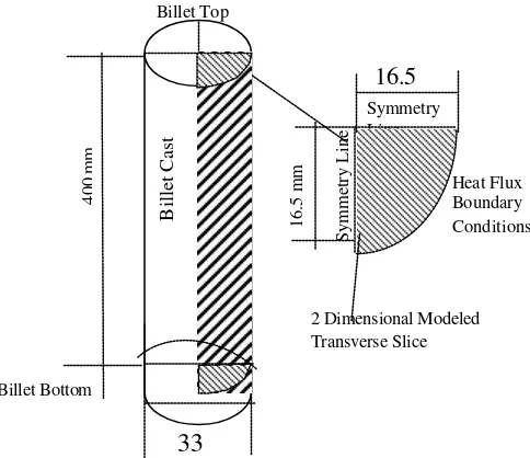
This section present the solution methodology of the heat transfer solidification temperature of the billet during continuous cast Wood’s metal with the finite element analysis simulation. The details of the Wood’s metal billet model simulated using the finite element method is shown in Fig. 4.
During billet cast withdrawal, heat from the billet surface is conducted to the surface copper mould’s wall. From the experimental work, it was noted that the temperature decreases sharply when the liquid metal is poured into the mould. The sudden drop of temperature is hindered after the temperature reaches the melting point temperature of the Wood’s metal. The temperature decreases in the mushy region at a lower rate in comparison to the liquid region. During billet withdrawal, the heat from the billet surface is conducted to surface copper mould’s wall. The temperature fall when the cooling water is circulated around the mould wall which will take place in about 20 second depends on the casting withdrawal speed. Outside the mould region, the radiation will enhance the completion of billet solidification.
To apply the solidification analysis for the continuous casting process of Wood’s
metal, the mould heat flux as a function of mould dwell time is required to be established. This function covers a wide range of casting conditions for different mould lubricants. This function is applied as the heat flux boundary condition for the finite element analysis. The lack of boundary condition information will undermine the ability of any previous or current analysis to predict the solidification temperature variation during the process of billet solidification.
The boundary condition for the mould cooling zone requires a knowledge of the longitudinal variation of heat flux in the mould, preferably, as a function of time. Unfortunately, insufficient data from literatures are available to formulate a mould zone heat flux boundary condition. This has been also reported by Savage and Pritchard, 1954 in their analysis for continuous casting process of steel. Therefore, the mould heat flux function for continuous casting of Wood’s metal is calculated from measurement of mould wall temperatures using embedded thermocouples as shown in Fig. 5.
It involves the placement of pairs of closely spaced thermocouple pairs at each measurement position in the mould wall. At each position, the two temperature
Figure 4. Transverse slice area of the Wood’s metal round billet cast model to be analyzed
Symmetry Line
Symmetry Line
Heat Flux Boundary Conditions
Billet Cast
400 mm
33
Billet Top
Billet Bottom
16.5 mm
16.5 mm
measurements are used to calculate the local heat flux with the integrated form of Fouries’s heat conduction equation (Holman, 1976) given as,
(
)
2 1 T T L k qt mw
m= − (11)
where kmw is the copper mould thermal
conductivity, Lt, is the distance between two
thermocouples, T1 and T2 are the two
measured temperatures. The thermal conductivity of the commercial copper material at 20 °C is 372 W/m °K. By taking the value of the heat flux, q, at each position across the length of the mould, a longitudinal heat flux profile can be generated.
Figure 5. Schematic diagram of the placement of the thermocouple at the hot surface of mould wall required for the calculation of the
heat flux.
The flux boundary condition was measured during the continuous cast of the Wood’s metal. The value of the heat flux was used as the input data for the ANSYS finite element analysis. The other required input data applied to the finite element analysis of the Wood’s metal solidification process in continuous casting, conducted by the experimental rig, is shown in Table 2.
Tabel 2 . Input data for finite element analysis of Wood’s metal billet
No. Parameters Values Unit
1. Wood’s Metal
Parameters
Igor et al., 1997 and Bejan, 1993 Conductivity (Kw) 12.8 W/m.°C
Specific Heat (cp) 147 J/Kg.°C
Latent Heat ( Lf ) 32567 J/Kg
Density (?) 1056 Kg/m3 Fraction of Solid (Fs) Linear -
Pouring Temperature ( Tp )
77 °C
Melting point temperature ( Tm )
69-71 °C
2. Casting Parameter Data from
Experimental Rig Billet Diameter ( D ) 33 mm Withdrawal time ( t ) 35 sec Mould Length (Lm) 400 mm
Length between Thermocouple (Lt)
0.01 m
Thermocouple Temperature (T1 – T2)
0.2 °C (Fig. 6.15) Casting Speed (Vc) 3.7 mm/sec
Oscillation Speed (Vm) 36.77 mm/sec
3. Copper Mould
Parameters
Bejan 28)
Conductivity ( Km) 372 W/m.°C
6. TYPICAL RESULT AND
DISCUSSION
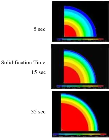
Figure 6 shows the temperature distribution of the solidified Wood’s metal in continuous casting obtained by applying the finite element simulation analysis. The solidification analysis of the Wood’s metal was considered when the mould was cooled by the water circulation around the mould’s wall.
As shown in Fig. 6 the blue colour area is denoted for the lowest temperature while the red colour area represents the highest temperature. At 5th second solidification time the temperature range is still in the mushy region which means no solid skin is formed during the withdrawal process. In the 15th second solidification time, the outer skin of the billet starts to
Hot Face
Cold Face
Mould Top
Mould Bottom
L
T= 10
mm
T
1T
2T
3become solid but the core of the billet remains liquid. Finally, at the 35th second solidification time, the remaining liquid core becomes smaller and the solid metal is progressed towards the middle of the billet.
The temperature distribution of the solidified billet along the symmetry line of the finite element billet model as represented in Fig. 4, is shown in Fig. 7. At the centre of the billet, the temperature of the metal is 71.8 °C for time t is 20 seconds, which is thus in the liquid region. The temperature decreases further to 69 °C, which is become solid at 15.3 mm from the centre of the billet. The thickness of the billet solid shell, d, determined by this finite element analysis is 1.2 mm.
Out side the mould wall region the components of heat transfer are radiations to the surrounding and free convection. Accurate assessments of the strand surface boundary conditions represented by the heat flux for the radiation cooling zones and for the mould are critical to the validity of the model under development. The effect of the radiation to the solidification temperature of the continuous casting Wood’s metal billet is not considered for this analysis.
5 sec
Solidification Time :
15 sec
35 sec
Figure 6. Solidificati on temperature of Wood’s metal continuous cast simulated using
the finite element analysis in ANSYS at various time.
68 68.5 69 69.5 70 70.5 71 71.5 72 72.5
0 1 2 3 4 5 6 7 8 9 10 11 12 13 14 15 16 17
Distance from the middle of the billet (mm)
Temperature ( C )
Figure 7. The temperature distribution of the Wood’s metal along the symmetry line at time
t = 20th second.
7. CONCLUSIONS
Continuous casting solidification simulations are performed in this work and are used to investigate temperature distribution and solidification time. It has been demonstrated that the heat transfer solidification with the consideration of the latent heat can be performed based on the enthalpy formulation of the energy equation. Further the application of the finite element method simulation using the commercial package ANSYS with the ability to simulate solidification process of bismuth based alloy is shown to be practical. The freezing range of the metal cast had been demonstrated which shows the effect on temperature of latent heat release in the mushy region. It has been shown in the present work the relationship between temperature, location and time of the solidification process which has been represented by the finite element method.
REFERENCES
Bejan A., 1993, Heat Transfer, John Wiley and Sons Inc. New York,
Birat J. P., Larrecq M., Lamant J. Y., Petegnief J., 1991, “The Continuous Casting Mold: A Basic Tool For Surface Quality And Strand
Productivity”, Steelmaking Confe
Chen J. H., Tsai H. L., 1990, “Comparison on Different Modes of Latent Heat Release for Modelling Casting
Solidification”, AFS Transac-tions,
pp. 539-546.
Cliff K., Dain R. J., 1967, “Computerized Calculation of Operating Conditions in Continuous Casting Machines”,
Journal of The Iron and Steel Institute, pp. 278-284,
Clyne T.W., 1984, “Modelling Heat Flow in
Solidification”, Mat. Sci. and Eng.,
Vol. 65, pp. 111-124.
Darle T., Mouchette A., Nadif M., Roscini M., Salvadori D., 1993, “Hydraulic Oscillation Of The CC Slab Mold At Sollac Florange: First Industrial Results, Future Developments”,
Steelmaking Conference
Proceedings, pp. 209-218.
Davies G. J., Shin Y. K., 1980,
“Solidification cracking of continuous
casting steels”, Solidification
Technology in the foundry and cast
house, University of Warwic k,
Conventry, pp. 517-523.
Handbook of Industrial Materials, 1992, 2nd Edition, Elsevier Advanced Technology, Oxford, UK.
Holman J. P., 1976, Heat Transfer, Fourth
Edition, McGraw-Hill Book Company,
New York,
Huang X., Thomas B. G., Najjar F. M., 1992,
“Modelling Superheat Removal during Continuous Casting of Steel Slabs”,
Metallurgical Transactions B, Vol. 23B, pp. 339-356.
Huang X., Thomas B. G., Najjar F. M., 1992,
“Modelling Superheat Removal during Continuous Casting of Steel Slabs”,
Metallurgical Transactions B, Vol. 23B, 339-356.
Igor S. Grigoriev, Evgenii Z., Meilikhov, 1997, Handbook of Physical
Quantities, CRC Press, Boca Rotan.
Laitinen E., Neittaanmaki P., 1988, “On Numerical Simulation of the
continuous casting process”, Journal
of Engineering Mathematics, Vol. 22, pp. 335-354,
Lally B., Biegler L. Henein H., 1999, “Finite Difference Heat-Transfer Modelling
for Continuous Casting”,
Metallur-gical Transactions B, Vol. 21B,
August, pp. 761-770.
Mahapatra R. B. Brimacombe J. K. Samarasekara I. V., Walker N., Paterson E. A., Young J. D., 1991,
“Mold Behavior and Its Influence on Quality in the Continuous Casting of Steel Slabs: Part 1. Industrial Trials, Mold Temperature Measurements, and
Mathematical Modelling”,
Metallur-gical Transactions B, Vol. 22B, pp. 861-874.
Mizikar, E. A., 1967, “Mathematical Heat Transfer Model for Solidification of Continuously Cast Steel Slabs”,
Trans. Met. Soc., AIME, Vol.
239(11), , pp. 1747 – 1753.
McDavies R. M., Thomas B. G., 1996, “Flux and Thermal Behavior of the Top Surface Flux/Powder Layers in Continuous Casting Molds”,
Metallurgical and Materials Transactions B, Vol. 27B, pp. 672-685,
Najjar F. M., Thomas B. G., Hershey D. E., 1995, “Numerical Study of Steady Turbulent Flow through Bifurcated Nozzles in Continuous Casting”,
Metallurgical and Materials Tran-sactions B, Vol. 26B, pp. 749-765. Samarasekara, I. V., Brimacombe, J.K.,
1978, “The Continuous Casting
Mould”, Int. Metals Review, Vol. 6,
pp. 286-300.
Savage, J., Pritchard, W. H., 1954, ‘The Problem of Rupture of the Billet in the
Continuous Casting of Steel’, Journal
of Iron and Steel Institute, Vol. 178, pp. 269 – 277.
Sheng D. Y., Jonsson L., 2000, “Two-Fluid Simulation on the Mixed Convection Flow Pattern in a Noniso-thermal Water Model of Continuous Casting
Tundish”, Metallurgical and
Materials Transactions B, Vol. 31B, pp. 867-875.
Shy, W., Pang Y., Hunter G. B., Wei D. Y., Chen M. H., 1992, “Modeling of Turbulent Transport and Solidification
During Continuous Ingot Casting”,
Takeuchi S. Miki Y., Itoyama S., Kobayashi K., Sorimachi K., Sakuraya T., 1991,
“Control of Oscillation Mark
Formation during Continuous
Casting”, Steelmaking Conference
Proceedings, pp. 73 – 33,
Takeuchi E., Brimacombe J. K., 1984, “ The Formation of Oscillation Marks in the Continuous Casting of Steel Slabs”,
Metallurgical Transactions B, Vol. 15B, pp. 493-509.
Thomas B. G., Lui D., Ho B.,1997, “Effect of Transverse Depressions and Oscillation Marks on Heat Transfer in the Continuous Casting Mould”,
Sensor and Modelling in Materials Processing: Technique and Applications, S. Viswanathan, R.G. Reddy, and J. C. Malas, eds,. The Minerals, Metals, & Materials Society, Warrendale, PA.
Voller V. R., Swaminathan C. R., 1991,
“General Source-Based Method for Solidification Phase Change”,
Numerical Heat Transfer, Part B, Vol. 19, pp. 175-189.
Voller V. R., Peng S., 1994, “An enthalpy formulation based on an arbitrary deforming mesh for solution of the
Stefan problem”, Computational