Philips
Semiconductors
AN710
Implementing fuzzy logic control
with the XA
Author:
Zhimin Ding
ABSTRACT
Most control applications involve the specification of a relationship between sensor signals and actuator outputs. Fuzzy logic provides an intuitive way to accomplish that. It allows the user to use linguistic rules to specify a nonlinear mapping between sensor signals and actuator outputs, thus provide a framework for programing an embedded system. Using a multi-joint robot system as a testbed, we implemented fuzzy logic on an 8051 compatible 16-bit microcontroller—the XA. The robot controlled by the XA running the fuzzy logic algorithm is able to carry out a goal-directed motor sequencing behavior. An 8XC552 is also used to directly interface with the robot and communicate with the XA through I2C. In addition to carrying out AD/PWM conversions, the ’552 also implements multiple loops of linear feedback for servo positioning and compliance control. This application note will demonstrate the implementation of Fuzzy Logic in an embedded control solution using the Philips XA microcontroller.
INTRODUCTION
Fuzzy logic was originally created as a mathematical model of human thought. It is said that fuzzy logic is able to capture the “vagueness” and “inexactness” of the concepts that we use for reasoning. In the past few decades or so, the main area of success with fuzzy logic has been in industry control. The application of fuzzy logic allows us to specify the relationship between sensor inputs and actuator outputs using “if...then...” type of linguistic rules. A fuzzy logic algorithm would be able to translate or interpolate these rules into a nonlinear mapping between sensor input signals and actuator outputs for feedback control [1]. Fuzzy logic makes it easy for a human designer to fine tune a control system through trial and error. Together with some other approaches such as artificial neural networks, genetic algorithm, etc., fuzzy logic is considered a useful tool for non-model based control system design1.
There are a number of software products available that would allow the user to design a fuzzy controller interactively with a special graphic user interface (GUI). These tools would usually generate C codes which can to be modified to fit into a user target platform. If you have to determine the parameters of your fuzzy logic control system on trial-and-error basis, it is certainly desirable to have some kind of graphic user interface so that you do not have to go into your code and make modification here and there.
As the number of inputs to a control system increases, the number of potential useful fuzzy rules increases dramatically and it becomes increasingly desirable to use some kind of automated method for rule synthesizing. There are a variety of such methods for doing this and active research is being carried out in this area currently. For example, the combination of fuzzy logic with artificial neural
networks, genetic algorithm and learning automata have proved to be effective in many applications.
In this application note, I will demonstrate the use of fuzzy logic in the XA. With a two-joint robot system as the testbed, I will discuss how to use fuzzy logic to tackle a specific control problem as well as some general programming issues related to the XA. Instead of exploring all the options that are out there, I will focus on one effective solution in this application note to get the readers quickly acquainted with the technique.
ROBUST CONTROL OF A “BUG”-LIKE
ROBOT LEG
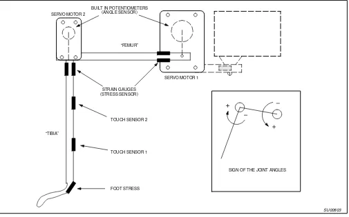
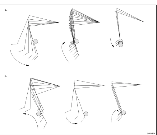
Figure 1 is a diagram of the robot leg. It is powered by two gearmotors and it has a passive foot-like structure at the end of the distal segment. We call the distal segment the “tibia”, and the proximal segment the “femur” after animals. The behavioral purpose of this robot is to grab an object within the space it can reach. The location of the object is unknown to the robot and changing periodically. This is very similar to a situation when an insect walking over a very rough terrain is trying to find an object (such as a tree branch or twig) to grab onto as a foothold. In this design, range sensing such as vision is not involved in the search of the object, as is the case with insects. Insects have developed a behavior shown in Figure 2 where they use their legs as probes to actively sense where the object is and then establish a foothold onto it through a simple reflex [2]. The active sensing reflex makes the
“substrate-finding” behavior quite robust.
The robot is equipped with two potentiometers which give us angular position readings for the two joints. On the two segments of the leg, strain gauges are pasted as force or touch sensors. The two strain gauges that are pasted near the junction of each actuator and the corresponding leg segment give us indications of the output torque of the two actuators. Three additional strain gauges are pasted along the distal segment (the tibia). These strain gauge readings can be decoded to determine where the touch between the leg and a external object has occurred. One of the strain gauges is pasted at the foot ankle region to signal foothold.
Our purpose of controlling this leg is to replicate the
“substrate-finding” behavior described above in a robust and reliable fashion (Figure 2). The challenge of this control problem lies in the fact that the position and touch sensors do not passively tell where the object is. The robot has to carry out active search movement to find out where the object is. In such a case, there is no way to linearly combine the sensor signals (or their derivatives and integrations) to produce the desired motor movement as in PID control. It is therefore an ideal application for us to try out fuzzy logic.
SIGN OF THE JOINT ANGLES SERVO MOTOR 1
“FEMUR”
STRAIN GAUGES (STRESS SENSOR)
TOUCH SENSOR 2
TOUCH SENSOR 1
FOOT STRESS BUILT IN POTENTIOMETERS
(ANGLE SENSOR) SERVO MOTOR 2
“TIBIA”
SU00803 Figure 1. A two-joint robot leg.
a.
b.
SU00804
Figure 2. Digitized robot leg movement trajectories from the “substrate-finding’’ behavior.
a. The leg encounters an object during the downward sweep of a search cycle; once contact is made, the leg slips up until it just clears the object and then comes back down to establish a foothold.
OUTLINE OF OUR APPROACH
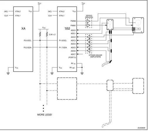
As illustrated in Figure 3, two Philips microcontrollers on an I2C-bus are used to control this robot. Firstly, an 8-bit 8XC552
microcontroller is used to interface directly with the robot. In addition to carrying out the necessary A/D and PWM functions for sensor and actuator interface, this 8-bit microcontroller also implements position and force feedback to shape the actuator dynamics so it becomes a position servo with proper compliance and damping properties. This is very important because the compliance in the actuators allows the robot to carry out contact based maneuvers stably and reliably. Together with the sensors and actuators of the robot leg, the 8XC552 implements “virtual muscles” as seen from the microcontroller at the upper level, which is the 16-bit XA microcontroller running the fuzzy logic algorithm. I chose an XA as
the fuzzy logic engine because of its higher arithmetics capability. The XA reads “crisp” sensor values from the 8-bit microcontroller through I2C interface and converts them into fuzzy membership grades. These values are evaluated by a set of fuzzy rules implemented in the XA in order to generate appropriate motor commands which are sent back to the ’552 through I2C. With I2C, we can easily put multiple robot legs in the control system as shown in Figure 3. For example, we can put together a six-legged hexapod robot.
In this application, the use of fuzzy logic and XA is not intended to replace low level linear, classical control carried out with the 8XC552. Instead, I use fuzzy logic in an augmented and distributed fashion. Fuzzy logic in XA and linear classical control in ’552 function in parallel and contribute to different aspects of the control.
SERVO
Figure 3. A diagram of the robot control circuit.
THE IMPLEMENTATION OF FUZZY LOGIC
ALGORITHM IN XA
In this section, I will explain some fuzzy logic related programming issues. I first explain the algorithm itself by going through the basic steps and then discuss how to implement the algorithm in the XA.
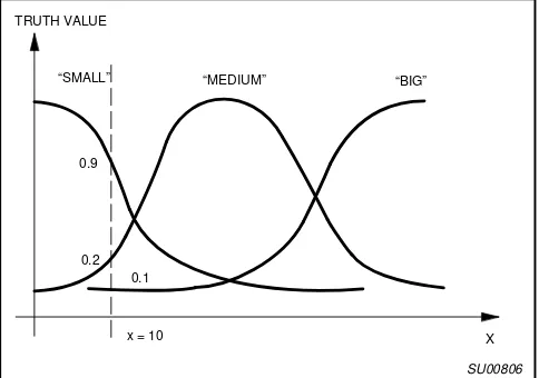
The first thing to do in a fuzzy logic control system is to translate a real sensor signal value into fuzzy membership grades. This procedure is called fuzzification. For example, if we have a sensor input value x within the range of 0 to 255, we want to find out to what extent is it “big” or “medium” or “small”. We can assign three functions corresponding to “big”, “medium” and “small” to do the translation. Those are called membership functions. As shown in Figure 4, if x = 10, then “x is small” has a truth value of 0.9; “x is medium” has a truth value of 0.2; “x is big” has a truth value of 0.1. In other words, we are mapping the value of x = 10 into a triplet (0.9, 0.2, 0.1).
Figure 4. An illustration of the fuzzy membership functions. For each x in the range of 0 to 255 (e.g., x=10), we can describe it as degrees of being “small’’, “medium’’ and “big’’ by using the three fuzzy membership functions.
The next thing to do at this point is to evaluate rules and find out their strengths. Suppose we have these three rules that involve input x.
• if x is small then z is low
• if x is medium then z is high
• if x is high then z is low
In this case, there is one “if ...” part in each rule, the strength of the rule is simply the truthfulness of the “if ...” part, which is called the antecedent. The truth values of the above three rules are 0.9, 0.2, and 0.1, respectively. If there are two or more antecedents, as in
“if x is small and y is big”, the strength of the rule is the smallest of the truthfulness of the antecedents (if the relationship between the two antecedents is an “or” instead of an “and”, we would use the largest value of the truthfulness of the antecedents).
The last thing is to find out is the real value of the output z from rule evaluation. Before we proceed, we need to define the membership functions for z. For example, we can simply assign z = 5 to “z is low” and z = 200 to “z is high”. These membership functions are impulse functions and they are generally called “singletons”.
To find out the precise (crisp) value of z according to the above three rules, we simply calculate the weighted average of
z-singletons according to the strength of the three rules, therefore,
z|x+10+5 * 0.9)200 * 0.2)5 * 0.1
0.9)0.2)0.1 [38 (1) What we have accomplished so far is to map x=10 to z= 38. According to the three rules, we can map every point of x in range 0–255 to some value of z as shown in Figure 5. Now the reader might be wondering what difference does it make if we just implement a look-up table to describe the relationship in Figure 5. The answer is, for a one-dimensional sensor input, you can implement exactly the same sensor to actuator mapping with a table and possibly save code complexity and memory space. It is, however, not so obvious how to implement multi-dimensional sensor to actuator mapping with tables. Furthermore, the fuzzy logic method allows the user to tune the system more easily. For example, in order to change a mapping relationship between input and output, for most people, it is more intuitive to change a set of linguistic rules instead of an array of parameters in a table.2
255
0 255 X
SU00807 Z
Figure 5. The curve in this figure represent a mapping relationship from x to z.
This relationship is interpolated from the above three fuzzy rules.
To implement the above algorithm in an XA, we need to consider the following issues. Since the membership functions do not usually change at run time, I use arrays stored in the code memory space to represent input membership functions. With this approach, I will not lose membership function information during power down, and also I can get membership functions of any shape. An easy way to choose the array size
(dimension) for membership functions is to let the array size equal to the resolution of the AD conversion. For example, with an 8-bit A/D input, I use arrays of size 256 to represent input membership functions. Furthermore, I also use 8-bit unsigned integers to represent the membership grades so that they go from 0 to 255 instead of 0 to 1. Suppose we have multiple input channels and for each channel, we divide the domain into a number of clusters; the total number membership function would be the number of input channels times the number of clusters in each input. For the example in Figure 4, we need three arrays or membership functions to characterize input x. In our robot application, we need a total of 40 membership function arrays and that takes about 10K code memory space.3
The following is an example that shows how to perform “fuzzification”. It plugs input value x into the membership function array that stands for “x is small”. The XA instruction movc A, [A+DPTR] (code memory access with indirect addressing with an offset) is used to access membership function data. this is an 80C51 compatible instruction. In XA, A is mapped to R4L and DPTR is mapped to R6.
x_small: db $ff,$fd,$f8,$f0, ... ;Membership function for ”x is small”.
x data 10h ;Input value x.
antecedent data 11h ;The resultant truth value of the antecedent: “x is small”.
;To find out the truth value of x being ”small”:
mov.w r6,#x_small ;Indirect pointer.
mov.b r4l,x ;Offset.
movc A,[A+DPTR] ;Code memory access. mov antecedent,r4l ;Return the result.
Once we have an appropriate way to implement membership functions, it is fairly straightforward to evaluate rules. In case there are multiple antecedents in each rule, however, we need to additionally implement some kind of min() or max() function to evaluate “and”, “or” relationships. The following is a code example that implements the min() function for fuzzy rule evaluation
num_antecedents equ 4 ;Number of antecedents in a rule, e.g. 4.
antecedents data 20h ;Truth values of the antecedents.
truth_rule data 30h ;The resultant truth value of the rule.
;To evaluate the truth value of the rule with multiple antecedents:
mov.w r0,#antecedents ;Index to antecedents.
mov.b r1l,[r0+]
loop: cmp r1l,[r0]
bl proceed
mov.b r1l,[r0] proceed: add r0,#1
cmp r0,#antecedents+num_antecedents
bcs loop ;Loop ”num_antecedents” times.
The last part of fuzzy logic loop, the “defuzzification” process is most computationally expensive. As shown in equation (1), we need to perform a series of 8×8 to 16-bit multiplications and a 32×16 to 16 division to get one final output value. This is to assume that our sensor values and membership grades have 8-bit resolution. We need to use 32-bit (long) integer to represent the numerator of equation (1) and 16-bit integer to represent the denominator. The following is an example of the defuzzification code segment.
num_rules equ 4 ;Number of rules, e.g. 4.
truth_rules data 10h ;The truth value of the rules (an array).
singletons data 20h ;The output singleton functions (an array);
z data 21h ;The crisp output value.
;To perform the defuzzification process
mov.w r0,#0 ;Index to the rules.
mov.b r1h,#0 ;Clear the high order bits of r1.
mov.w r4,#0 ;Initialize low order bits of the numerator.
mov.w r5,#0 ;Initialize high order bits of the numerator.
mov.w r6,#0 ;Initialize the denominator.
loop: mov.b r1l,[r0+truth_rules]
mov.b r2l,[r0+singletons]
mulu.b r2l,r1l ;8x8=16 multiplication.
add.w r4,r2 ;r4 stores the numerator.
addc.w r5,#0 ;add carry to higher bits.
add.w r6,r1 ;calculate the denominator.
add.w r0,#1 ;increment the index.
cmp r01,#num_rules
bcs loop
divu.d r4, r6 ;32/16 –> 16 unsigned division.
mov.w z, r4
IMPLEMENTATION OF A COMPLIANT ROBOT
ACTUATOR THROUGH SENSORY FEEDBACK IN
AN 8XC552
As stated earlier, we intend to use fuzzy logic in an augmented fashion. In this application, the low level servo control can still be handled more easily with conventional linear feedback. In this section, we focus on these low level implementation issues. Specifically, we will discuss the interface between the 8XC552 and the sensors and actuators of the robot leg.
Most robot actuators use position feedback to implement a closed-loop position servo. In order to achieve position accuracy, those actuators are usually quite rigid. Although robots powered by this kind of servo are usually able to make unconstrained movement smoothly and quickly, they become unstable and behave erratically upon contact with external objects [3]. With sufficient power, this kind of robot could also be dangerous to human operators and things around it. It is therefore often necessary to avoid any contact situation. Animal and human muscles, on the other hand, are very versatile due to the fact that they are usually compliant and more importantly, the compliance can be actively controlled.
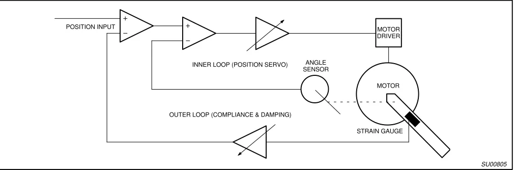
Figure 6 illustrates the implementation of our robot actuator as a “virtual muscle”. I use a DC gearmotor as the core. Each motor is integrated with a position sensor (potentiometer) and a feedback circuit that acts as a position servo. Since the gear motor is non-backdrivable, without the additional circuitry described below, the servo system is quite rigid, that is to say, the output angle is determined by the input command signal, and largely unaffected by external torques acting on the joint. To achieve actuator properties that resemble those of muscles, I add additional feedback pathways through an 8XC552 to allow us to control compliance and damping
properties. The torque signal from strain gauges is fed back to the position command signal to form a compliance feedback loop. The gain of the compliance loop determines the extent to which the servo moves in response to external forces, thus establishing compliant properties (see Figure 6, the outer loop). The dynamic properties of the integrated sensor-actuator such as the compliance and the damping ratio can be controlled by adjusting the variable gains and low pass filter time constants in the compliance feedback loop. With compliant robot joint actuators, we effectively added a cushion between the robot and the objects it is in contact with and therefore get a significant improvement in contact stability [3], [4]. With an adjustable joint compliance, the robot can serve as both a contact based probe and an effector that is capable of exerting forces and maintaining positional accuracy depending on the behavior context.
The 8XC552 carries out both position and force feedback. The feedback loop is implemented in a timer interrupt service routine that is called every 0.1ms. After the 8XC552 completes the sensory feedback function for the tuning of a compliant actuator dynamics, it stores copies of all the sensor values in a buffer for access by the XA through I2C to control the output angle and compliance of the robot joint. The 8XC552 thus implements a compliant actuator with electronically controllable compliance and presents itself as an I2C slave to the XA.
Notice that the feedback pathways implemented thus far are strictly linear feedback loops that are intended for actuator control. This part of the feedback can be done easily without fuzzy logic4. On the other hand, the control at this level has to be done in hard real time to ensure dynamic stability.
POSITION INPUT
OUTER LOOP (COMPLIANCE & DAMPING)
INNER LOOP (POSITION SERVO) ANGLE SENSOR Figure 6. An integrated sensor-actuator assembly for compliant robot joint actuation.
The active compliance is accomplished through stress feedback.
Rule base generation
In this application, fuzzy logic is used to control the robot at higher level, that is, the coordination between joints in order to carry out meaningful motion sequence. As mentioned earlier, the main advantage of fuzzy logic is that the user can design a control system based on intuition. There are, therefore, not many rules to follow to generate the fuzzy logic rules. In this section, we discuss a few techniques that we used in this specific application.
In addition to the strain and position sensor inputs mentioned earlier, a software generated timer signal implemented in XA is fed to the fuzzy evaluator internally and this counts as another sensory input. The timer counts from 0 to 255 repeatedly and they were clustered into three fuzzy sets corresponding to the three phases of the leg searching cycle, namely “start”, “probe” and “retract”. This is necessary because the control of the leg involves the generation of rhythmic movement in the absence of any specific sensor inputs. The rhythmic movement ensures that the robot will engage in active searching when it is not in touch with any object. The timer input functions as a “central pattern generator”.
In addition to the soft timer, there are a total of 7 sensor inputs to this system. Each of sensor values are clustered into 5 clusters. For example, a quantity ranging from 0 to 255 can be characterized by membership functions corresponding to, “very small”, “small”, “medium”, “big”, “very big”. For each output, there could be as much as 57 * 3 = 234375 rules. It is obviously impossible for us to manually try all the rules on “trial-and-error” basis. Notice that for this system, the signals detected from the various sensors are highly correlated. For example, when touch sensor 1 is signaling positive, touch sensor 2 is likely to signal positive also (but not vice versa). It is therefore unnecessary to try a rule like
.IF touch sensor 1 positive-big AND touch sensor 2 negative-big AND ...
THEN ...
because this situation does not exist.
By this analysis we can reduce the number of rules significantly. Here are a set of rules that are used to give the performance shown in Figure 2. Additional rules can be put in to make the leg more versatile.
.IF tibia stress is zero AND femur stress is zero AND timer is start
THEN femur output is negative-small AND tibia output is positive-big.
.IF tibia stress is zero AND femur stress is zero AND timer is probe
THEN femur output is positive-big AND tibia output is negative-big.
.IF tibia stress is zero AND femur stress is zero AND timer is retract
THEN femur output is negative-big AND tibia output is negative-big.
(* The above three rules are responsible for the generation of the three phased search pattern when the leg is not in touch of anything).
.IF touch sensor 1 is negative-small THEN femur output is negative-big AND tibia output is negative-big.
.IF touch sensor 2 is negative-small THEN femur output is negative-big AND tibia output is negative-big.
.IF tibia stress is negative-small THEN femur output is negative-big AND tibia output is negative-big.
.IF touch sensor 1 is positive-small THEN femur output is negative-big AND tibia output is zero.
.IF touch sensor 2 is positive-small THEN femur output is negative-big AND tibia output is zero.
.IF tibia stress is positive-small THEN femur output is negative-big AND tibia output is zero.
.IF femur angle is negative-big and tibia angle is negative-big THEN tibia output is positive-big.
(* The above rules are responsible for the retract movement when the leg is in touch with an object in a way as shown in Figure 2.)
.IF foot stress is negative-small THEN femur output is positive-small AND tibia output is negative-small.
(* This rule is responsible for the foot to keep in contact with an object by pressing onto it.)
DISCUSSIONS
The feedback pathways in a control system can often be
categorized into two classes, linear (e.g., PID control) and nonlinear, and they often serve quite different purposes. In this application, the linear feedback control loops are implemented to “tune” the robot joint dynamics in some desired fashion, i.e., position servo with some compliance, whereas the nonlinear feedback control reflexes are used to control the coordination between multiple robot joints in order to achieve a more concrete objective such as the requirement for the robot to grab and hold onto an object. The linear feedback algorithms are usually straightforward to implement but they generally have high speed requirements for stability reasons. Nonlinear feedbacks, on the other hand are usually computationally more intensive due to the requirements for interpolation (fuzzy logic algorithm does exactly that). This requirement will usually slow things down a little bit. In this paradigm, the stability and robustness of a system depends critically on the speed of the linear feedback layer and is somewhat less sensitive to the speed of the fuzzy logic loop. We envision that with our next generation of XA (XA-S3). We can integrate all of these functions into one chip. We will use the XA multi-tasking capabilities so that we implement several layers of feedback, some of which carry out simple, but fast servoing for actuator control and the others running fuzzy logic for goal-directed motor sequencing behavior.
REFERENCES
[1] Castro, J.L., Fuzzy logic controllers are universal approximators. IEEE transactions on system, man, and cybernetics, Vol. 25, No. 4, 629-635.
[2] Bassler, U. (1991) Interruption of searching movements of partly restrained front legs of stick insects, a model situation for the start of a stance phase? Biol. Cybern. 65, 507-514.
[3] Hogan, N. (1988) On the stability of manipulators performing contact tasks. IEEE Journal of Robotics and Automation, vol. 4, 677-686.
[4] Ding, Z., Nelson, M.E. (1995) A neural controller for single-leg substrate-finding: a first step toward agile locomotion in insects and robots. In: Computation and Neural Systems 3
F. Eeckman and J.M. Bower, eds., Kluwer Academics Press.
Philips Semiconductors and Philips Electronics North America Corporation reserve the right to make changes, without notice, in the products, including circuits, standard cells, and/or software, described or contained herein in order to improve design and/or performance. Philips Semiconductors assumes no responsibility or liability for the use of any of these products, conveys no license or title under any patent, copyright, or mask work right to these products, and makes no representations or warranties that these products are free from patent, copyright, or mask work right infringement, unless otherwise specified. Applications that are described herein for any of these products are for illustrative purposes only. Philips Semiconductors makes no representation or warranty that such applications will be suitable for the specified use without further testing or modification.
LIFE SUPPORT APPLICATIONS
Philips Semiconductors and Philips Electronics North America Corporation Products are not designed for use in life support appliances, devices, or systems where malfunction of a Philips Semiconductors and Philips Electronics North America Corporation Product can reasonably be expected to result in a personal injury. Philips Semiconductors and Philips Electronics North America Corporation customers using or selling Philips Semiconductors and Philips Electronics North America Corporation Products for use in such applications do so at their own risk and agree to fully indemnify Philips Semiconductors and Philips Electronics North America Corporation for any damages resulting from such improper use or sale.
Philips Semiconductors 811 East Arques Avenue P.O. Box 3409
Sunnyvale, California 94088–3409 Telephone 800-234-7381
Philips Semiconductors and Philips Electronics North America Corporation register eligible circuits under the Semiconductor Chip Protection Act.
Copyright Philips Electronics North America Corporation 1996 All rights reserved. Printed in U.S.A.