DOI: http://dx.doi.org/10.21609/jiki.v9i1.365
PERFORMANCE COMPARISON OF USART COMMUNICATION BETWEEN REAL TIME OPERATING SYSTEM AND NATIVE INTERRUPT
Novian Habibie1, Machmud Roby Alhamidi1, Dwi M J Purnomo1, and Muhammad Febrian Rachmadi2
1Faculty of Computer Science, Universitas Indonesia, Kampus Baru UI, Depok, 16424, Indonesia 2School of Informatics, The University of Edinburgh, 11 Crichton Street, Edinburgh EH8 9LE, United
Kingdom
E-mail: [email protected], [email protected]2 Abstract
Comunication between microcontrollers is one of the crucial point in embedded sytems. On the other hand, embedded system must be able to run many parallel task simultaneously. To handle this, we need a reliabe system that can do a multitasking without decreasing every task’s performance. The most widely used methods for multitasking in embedded systems are using Interrupt Service Routine (ISR) or using Real Time Operating System (RTOS). This research compared perfomance of USART communication on system with RTOS to a system that use interrupt. Experiments run on two identical development board XMega A3BU-Xplained which used intenal sensor (light and temperature) and used servo as external component. Perfomance comparison done by counting ping time (elapsing time to transmit data and get a reply as a mark that data has been received) and compare it. This experiments divided into two scenarios: (1) system loaded with many tasks, (2) system loaded with few tasks. Result of the experiments show that communication will be faster if system only loaded with few tasks. System with RTOS has won from interrupt in case (1), but lose to interrupt in case (2).
Keywords: embedded system RTOS, interrupt, USART, performance analysis
Abstrak
Komunikasi antar mikrokontroller adalah salah satu hal krusial dalam sebuah embedded system. Di sisi lain, embedded system juga harus dapat menangani beberapa task/pekerjaan dalam satu waktu. Untuk itu, diperlukan sebuah sistem yang dapat melaksanakan proses multitasking tanpa mengganggu per-forma dari masing-masing task yang ada. Ada dua metode multitasking yang populer digunakan pada
embedded system, yaitu menggunakan Interrupt Service Routine (ISR) dan menggunakan Real Time
Operating System (RTOS). Penelitian ini membandingkan performa komunikasi USART pada
mikro-kontroller dengan RTOS dengan yang hanya menggunakan interrupt. Uji coba dilakukan pada dua
development board XMega A3BU-Xplained dengan sensor internal (cahaya dan temperatur) dan
men-jalankan sebuah servo. Uji performa dilakukan dengan menghitung waktu ping, yaitu waktu yang dibu-tuhkan untuk mengirim satu karakter data ke board tujuan dan menerima balasan satu karakter sebagai tanda bahwa data telah diterima oleh board tujuan. Skenario yang digunakan adalah (1) sistem memiliki banyak task, dan (2) saat sisem memiliki sedikit task. Berdasarkan eksperimen yang dilakukan, secara umum proses komunikasi akan berjalan lebih cepat jika sistem hanya mempunyai sedikit task. Sistem dengan RTOS akan memiliki waktu ping yang jauh lebih cepat dari yang menggunakan interrupt pada kasus (1), namun sistem dengan interrupt akan lebih cepat dari sistem dengan RTOS pada kasus (2).
Kata Kunci: embedded system, RTOS, interrupt, USART, analisa performa
1. Introduction
Nowadays the usage of embedded systems are widely spread in every aspects of our life. It is because embedded systems are the right solution to implant an automatic behaviour or responses into physical world which is small, low-powered, and specific to one dedicated purpose. Implementation of embedded system are everywhere, start from daily utensils like refrigerator, television,
calcula-tor, until many device that runs daily life like traffic light, automatic gate in the railstation, etc.
Although one embedded systems can be only dedi-cated to specific purposes, its purposes itself may contain some tasks. Because of that, one of a capability that embedded system must have is an ability to handle multiple tasks without fail. To do that, the system that can handle parallel compu-tation in small and low compucompu-tational ability is urgently needed. One of the solution by using
1, February 2016
rupt Service Routine (ISR) to run tasks as a process that interrupting its main program simultaneusly. Another solution is Real Time Operating System (RTOS), a tiny operating system that can fit into embedded system’s device and run processes as tasks that run in specific time slice. Either interrupt or RTOS have its own advantages and disadvantag-es, depends on needs of the system.
Another crucial point for embedded system is an ability to communicate and exchange data from one microcontroller to another. With communica-ting each other, the functionality of the system can be increased and can be made as a wider system that can coordinate each other. There is many me-thods to do a communication between device, one of them is communication using USART (Univer-sal Synchronous Asynchronous Receiver Transmi-tter) method.
Communication between system usually fol-lowed with another tasks that run in parallel, e.g. sensor reading or move an actuator. However, so-metimes comunication process disturbed by ano-ther task, so in result communication process can be slower than expected and/or occurred an error that cause data loss. To overcome that, the system that capable to run parallel processes without re-duce any process’s performance is needed.
Several research about embedded system and RTOS have been conducted in recent years. The latest one, Manju Nanda et al. [1] conducted re-search about qualifying RTOS for use in safety cri-tical applications using formal methods due to ef-fectiveness and preciseness. Manju Nanda et al [4] provides guidelines for development and imple-mentation of formal approach to qualify a Comm-ercially off the Shelf (COTS) RTOS as per the civil aerospace standard RTCA DO-178C.
Yonghyun Hwan et al. [2] present an accurate timed RTOS model within transaction level models (TLMs). There are two key features used in this re-search. The RTOS behavior model provides dyna-mic scheduling, IPC (inter-process communicati-on), and external communication for timing anno-tated user applications. The RTOS overhead model
has processor to specific pre-characterized over-head information to provide cycle approximate es-timation. To demonstrate the model, Yonhyun Hw-an et al [2] used a multicore platform executed a JPEG encoder and provide results that RTOS mo-del present high accuracy.
Su-Lim TAN and Tran Nguyen Bao Anh [3] present a research about RTOS for small microcon-troller. Su-Lim TAN and Tran Nguyen Bao Anh [3] used 16 bit microcontroller to perform RTOS mul-titasking. To demonstrate the ease of RTOS plat-form migration, the mTKernel RTOS is chosen for porting to the H8S/2377 16-bit microcontroller.
Ji Chan Maeng et al [4] present a research ab-out produce an RTOS specific code using an auto-mated tool and model-driven approach embedded software development. Generic RTOS APIs was defined to capture most of typical RTOS ser-vices and for describing application’s RTOS related be-haviour at an early stage. Generic RTOS APIs have been transformed into RTOS specific APIs using an automated transformation tool.
Fabiano Hessel [5] present a research about abstract RTOS model that allows refining the ab-stract model to an implementation model at lower abstraction levels. Fabiano Hessel [5] used C lang-uage with some extension to build the model and as a results fifty task with four priority levels shows the usefulness of this model.
Our previous research [6], do a comparison between RTOS and Interrupt using ultrasonic sen-sor and rack movement mechanism where it will move from distance 0 cm to 10 cm repeatedly. De-fined threshold at a certain distance that is begin-ning, middle and end. Ultrasonic sensor will indi-cated “HIT” if distance between assigned threshold and rack movement is equal. Result shows that RTOS has higher accuracy performance than Inter-rupt butlesser precision.
Figure 2. Schematic of RTOS scheduling. Priority
High
Low
time
Task 1 Task 1
Task 2 Task 2
Task 3
Preemption Task Completion
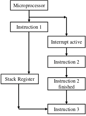
Figure 1. Schematic of interrupt Microprocessor
Instruction 1
Stack Register
Instruction 3 Instruction 2
In this research, the peformance comparison between RTOS and native interrupt will be inves-tigated in the case of serial communication betwe-en microcontroller. This research will test perfor-mance of USART communication while undergo-ing another some other tasks.
The rest of this paper is organized as follows. Section 2 describe the methodology used in this re-search. Section 3 presents results and analysis of experiment. Finally, section 4 presents conclusions of this paper.
2. Methods
This research focused on testing the performance of USART communication on various multitasking environment. Performance in this research measu-red by two aspects: (1) communication speed, and (2) communication reliability. Experiments con-ducted on two multitasking system which connec-ted each other with USART communication. Each board have an identic environment and specifica-tions, either hardware or software.
Communication speed can be measured by obtaining data of amount of elapsed communica-tion time. This aspect tested by conduct “ping” pro-cess and count its elapsed time. Similar to ping in networking [7], ping is a process to check a reacha-bility of destination device. Ping conducted by sen-ding a packet of data to destination device and get a reply data as a sign that the data has been recei-ved. For experiment on this research, ping conduct-ed as character sending and receiving process. Ping function transmit character ‘t’ to destination board, and the destination board will reply with character ‘r’. Elapsed time obtained by count the time diffe-rences between data sending and receiving process. For each experiment, ping conducted several times and the mean of ping time become the result. Detail of experiment process explained in sub-section 2.2, on experiment scenarios subsection.
Reliability of communication conducted to see how much error occurred when USART runs on various condition. To see the system’s error, ex-periment still use the same process as ping does, but it now focused on the amount of data that trans-miited and received. As explained above, each ex-periment conducted ping several times. To check reliability of the system, this experiment will count the differences between the amount of data which is received and retransmitted. This aspect obtained in each board separately. The amount of received ping accumulated on the destination board, and the amount of obtained reply data that comes from des-tination board accumulated in source board. The amount of differences between received ping and received reply become amount of packet that loss on ping process. From amount of loss packet,
relia-bility of the system can be measured and analyzed. Detail of this aspect explained in section 4, sub-section experiment scenarios.
RTOS and Native Interrupt
RTOS is a new approach as an alternative of inter-rupt in microcontroller world. Its capability of un-dertaking multitask performance better than native interrupt has become an attraction for many of re-searchers. RTOS eminences comprise flexibility of architecture can be empowered, reliable for many tasks, actively developed, simple, and many others [8].
The main difference between RTOS and nati-ve interrupt is illustrated in Figure 1 and Figure 2. Figure 1 shows the task management in RTOS. If there is task whose higher priority, the lower prio-rity task will be suspended and the high prioprio-rity ta-sk will be executed. Whereas in native interrupt, the task which is inside the interrupt cannot be inte-rrupted by another task before the previous task fi-nished (Figure 2).
The utilization of RTOS (in this research free-RTOS was employed) due to its capability of multi-tasking. Multitasking is highly related to setting the priorities of tasks. In the freeRTOS the priorities of tasks can be determined by utilizing FreeRTOSConfig.h. The aforementioned priorities are ranging from 0 to (configMAX_PRIORITIES -1) [9]. The value of (configMAX_PRIORITIES-1) could be defined freely, as long as it does not ex-ceed the RAM capacity. However, if the chosen va-lue is 1 (one) for configUSE_PORT_OPTIMISED
_TASK_SELECTION in the FreeRTOSConfig.h, the value of configMAX_PRIORITIES is limited
to 32. Whereas the task whose priority of 0 is called tskIDLE_PRIORITY.
In this research, native interrupt was also em-powered to be compared with RTOS. The priorities of the above mentioned interrupt are listed in the microcontroller datasheet [10]. To cite an instance, RESET whose the highest priority. To assign the in-terrupt, Interrupt Service Routine (ISR) must be written in the source code. Further-more, to active-te the global inactive-terrupt in order to make the inactive-terrupt executed, macro sei() was assigned.
Interrupt employed to the system by activate the timer interrupt feature. Timer interrupt will in-terrupt main program with specific task in a spe-cific time slice. Timer interrupt will execute the ta-sk after the timer is overflow. The amount of tick required (TC) to make timer overflow can be deter-mined by put a value to the Timer Counter Register (TCCR) from equation(1) as follows:
𝑻𝑻𝑻𝑻= 𝒕𝒕𝒓𝒓𝒓𝒓𝒓𝒓
1, February 2016
Which 𝒕𝒕𝒓𝒓𝒓𝒓𝒓𝒓 is actual amount of time required (in second), and 𝑻𝑻𝑻𝑻𝑪𝑪𝑪𝑪is clock time period of the mi-crocontroller. 𝑻𝑻𝑻𝑻𝑪𝑪𝑪𝑪= 𝒑𝒑𝒓𝒓𝒓𝒓𝒑𝒑𝒑𝒑𝒑𝒑𝒑𝒑𝒓𝒓𝒓𝒓/𝒇𝒇_𝑻𝑻𝑪𝑪𝑪𝑪 , where 𝒇𝒇𝑻𝑻𝑪𝑪𝑪𝑪 is clock of microcontroller and prescaler is divider of real frequency depends on how long ti-mer defined. Prescaler defined as a value of the po-wer of two, e.g. 1,2,4,8, etc.
USART
Communication between devices in embedded sys-tems have two different forms, parallel and serial communication. Parallel communication employs transmitting and receiving data via multiple GPIO port, which each port represent one bit of data. On the other hand, serial communication transmit or receive data in one port only, and data transmitted sequentially in a form of data packet. Each parallel or serial communication have its own advantages and disadvantages. Parallel communication can ha-ve a faster speed because it can transmit/receiha-ve multiple data at one time because it use multiple ports. However, the usage of multiple port itself
be-came its disadvantages because it’s too costly and give extra complexity to the system. Nowadays, se-rial communication is commonly used because it use less port and transmit data in a form of packet. Illustration of differences between parallel and se-rial communication can be seen on Figure 3.
Universal Synchronous Asynchronous Rece-iver Transmitter (USART) is one of a serial com-munication protocol. In general it uses two ports, one for transmitting data (TX port), and another one is for receiving data (RX port). If necessary, it can use one additional port as a clock for sync-hronous communication. USART can be activated via USART register in microcontroller. USART ha-ve three modes, asynchronous normal mode, asyn-chronous double speed, and synasyn-chronous mode.
Similar to interrupt, performance of USART depends on system clock and baud rate. System clock can be defined based on specification of mic-rocontroller used on the system. Baud rate is a term of how many data/symbol can be transmitted in one time, which one symbol can contain more than one bit.
If N is an amount of bits in one symbol, re-quired symbol to be sent is 𝑺𝑺= 𝟐𝟐𝑵𝑵. Baud rate can
Figure 3. Illustration of comparison between parallel and serial communication
TABLE 1
SPECIFICATION OF ATXMEGA256A3BU-AU
Specification Value
Flash 256KB + 8KB
Component/Feature Chip Port / Board Port
USART Transmit Port (TX)
J1-PIN3 / PC3
USART Receive Port (RX)
J1-PIN2 / PC2
Servo Motor Data J1-PIN0 / PC0
GPIO to Arduino J1-PIN4-5 / PC4-5
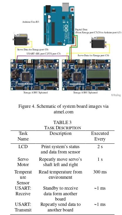
Servo Data (to Xmega port C0) USART (RX port C2/TX port C3)
Xmega A3BU Xplained Xmega A3BU Xplained
Servo Data (to Xmega port C0) Digital Data
(From Xmega port C5,C6 to Arduino port 4,5) Arduino Uno R3
Figure 4. Schematic of system board images via atmel.com
TABLE 3 TASK DESCRIPTION
Task Name
Description Executed
Every
LCD Print system’s status
and data from sensor
2 s
Servo Motor
Repeatly move servo’s shaft left and right
1 s
Temperat ure Sensor
Read temperature from environment
300 ms
USART: Receive
Standby to receive data form another
board
~1 ms
USART: Transmit
Repeatly send data to another board
be converted as bit rate by counting 𝑹𝑹=𝒃𝒃𝒑𝒑𝒃𝒃𝒃𝒃𝒓𝒓𝒑𝒑𝒕𝒕𝒓𝒓 𝒙𝒙𝒑𝒑𝒍𝒍𝒍𝒍𝟐𝟐𝑺𝑺. Correlation of system clock and baud rate, known as BSEL, used as input value to UBBR reg-ister. For example, the value for UBBR in USART asynchronous normal mode can be obtained from equation(2). rate. Common used baud rate are 4800, 9600, 19200, and so on.
Experiment Environment
Hardware
Experiments run on development board Xmega A3BU-Xplained, which use microcontroller ATX-mega A256A3BU manufactured by Atmel. Full specification of the board can be seen on Table 1. Internal components from the development board such as button, LED, monochrome LCD, and inter-nal sensor (light sensor and temperature sensor) have been used as the components to simulate the multitasking system. Experiments use two identi-cal development board powered with USB cable and connected each other with USART communi-cation, which use port Rx (receiver) and Tx (trans-mitter). For external components, servo motor is connected to each board in port SDA to use PWM feature from the microcontroller. To count ping ti-me from the system, one of the developti-ment board connected to Arduino Uno board via GPIO. Ardui-no will connected to the destkop computer via USB serial. Arduino Uno acts as a timer to count elapsed time for ping time
from XMega board. For further hardware details, schematic diagram is on Figure 3, and external components port connection table on X Mega boa-rd is on Table 2.
Software
Program that used in this research for XMega boa-rd was developed on Atmel Studio 7 IDE, MinGW C compiler, and firmware downloader FLIP from atmel. The program use Atmel Software Framewok (ASF) library as main library to use various featu-res of development board Xmega A3BU-Xplained. For Arduino Uno board, the program developed on Arduino IDE with standard Arduino Library.
RTOS which is used in this research is Free-RTOS, an open source RTOS for various microcon-troller. Raw FreeRTOS source code obtained from its official website, http://freertos .org. Raw source code has been configured to be compatible with
Xmega board and only use a required features. However, current FreeRTOS version is not compa-tible to Xmega-family microcontroller yet. To ov-ercome this, the additional configuration from [11] has been used in configur-ation file of Free-RTOS. Timer counter used as data logger in arduino was Timer1 library from Arduino Library[12]. Timer1 provide library for timer counter in mili-second up to two decimal places.
Multitasking Configurations
This reseach conduct two type of multi-tasking sys-tem: (1) system with primitive Interrupt Service Routine (ISR) and (2) system with RTOS. Both system loaded with five parallel tasks : LCD dis-play, servo, temperature sensor, USART receive process, and USART transmit process. Each of th-em scheduled in specific time. Detail of parallel tasks described in Table III.
This experiment use interrupt library from Atmel Software Framework (ASF): Programmable Multi-level Interrupt Controller (PMIC) module, specifically use timer interrupt. Based on feature of XMegaA256ABU, microcontroller used for this experiment provide four timer/counter register: C, D,E,F with each of them have two channel, channel 0 and 1. For this experiment, timer counter used for parallel task are C1 (USART: transmit), D0 (LCD), D1 (Temperature Sensor), E0(servo), E1 (USART: receive).
Configuration used in this research followed the standard of FreeRTOS, which configuration of system is defined in FreeRTOSConfig.h file and when the task is created via the xTask-Create() function. For this research, every task is configured with the identical settings. Each task assigned to the same priority (priority 0) to assure they have the same amount of time slice. Moreover, each task have the same depth of stack, 500.
Software Interface Configurations
System used for experiment have sensor as input simulation and display and actuator as output simu-lation. For software driver, system use ASF modul-es to simpify implementation procmodul-ess. Internal tem-perature sensor from XMega board used to simula-te input via Analog to Digital Conversimula-ter (ADC) module, which connected to ADC register A. Sys-tem also use GFX Monochrome module to print data from system. PWM used in this system run via direct register access on register C0.
USART Configurations
1, February 2016
and receive data in character form, capacity of data for each packet is 8-bit length. USART for this ex-periment not use any parity bit and stop bit. Experiment Scenarios
The experiments are divided into two main scenari-os: (1) count and compare elapsed time of USART communication between two board, and (2) com-pared USART’s reliability by comparing transmit-ed and receivtransmit-ed data in the destination board. Sce-nario (1) itself also have two sub-sceSce-narios: count time when system is (1.a) heavy-loaded (run many tasks) and (1.b) light-loaded (only run fewer tasks than first scenario). Scenario (2) has two compo-nents: (2.a) check differences of on amount of sent data with amount of received data and (2.b) send and receive string as sequence of characters. Table 4 shows scenario conducted in this research. Table 5 shows experimental parameter used in the scena-rio.
In details, scenario (1) counts ping time. For each experiment, ping is performed 100 times. Ping time obtained from total 100 ping time divided wi-th 100 as a mean time. For scenario (1), bowi-th sys-tems with RTOS and interrupt use same process
and same amount of tasks. For sub-scenario (1.a), system is loaded with 5 different tasks: LCD, but-ton, light sensor, temperature sensor, and servo, and in subscenario (1.b), system is only loaded wi-th button and LCD wiwi-th minimum display. See Ta-ble III for detail of task descriptions.
Scenario (2) will test data transmission and reception realibility. As same as scenario (1), each sub-scenario, (2.a) and (2.b) tested with three con-figurations: heavy-loaded, light-loaded and hybrid (heavy-light) loaded. Scenario (2.a) counts and co-mpares amount of data received on destination bo-ard respect to replied data received on sender boa-rd. Scenario (2.b) tests data consistency by sending string as sequence of characters. Received string on destination board will be compared to sent string on source board to find whether any error or not. 3. Results and Analysis
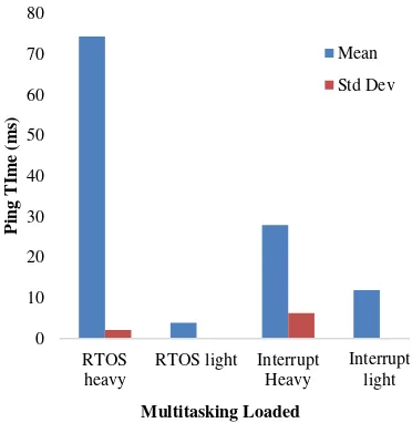
Figure 5 shows the ping time comparison between RTOS and Interrupt if multitasking is run in heavy loaded system or light loaded system in baud rate 4800. The RTOS in light loaded outperformed the Interrupt. On the contrary, the Inter-rupt shows bet-ter performance in heavy loaded task. In RTOS, multitasking will be done within the specified time, which means that each task will be done when the specified time arrives. On the other hand, at the In-terrupt task will be done by inIn-terrupting main pro-cess.
Results from the experiments show that ave-rage ping time for the RTOS in heavy loaded is 74.011 ms and the Interrupt in the same configur-ation is 33.249 ms. In light loaded experiment, the average ping time for the RTOS is 3.912 ms and the Interrupt is 11.943 ms.
TABLE 4 EXPERIMENTAL SCENARIO
Scenario/ Parameter Baud Rate Task
Load
Ping Time V V
Data Loss V V
TABLE 5 EXPERIMENTAL PARAMETER
Baud Rate
Figure 5. Ping time comparison between RTOS and Interrupt in Baud Rate: 4800
0
Figure 6. Ping time comparison between RTOS and Interrupt in Baud Rate: 9600
Figure 6 shows the ping time comparison bet-ween RTOS and Interrupt if multitasking is run in heavy loaded system or light loaded system in baud rate 9600. Similar to previous experiment which used baud rate 4800, RTOS gives slower communi-cation than interrupt in heavy-loaded task but runs faster in light-loaded system (RTOS heavy-loaded = 74.357 ms; light-loaded = 3.884ms, Interrupt heavy-loaded = 27.923 ms; light-loaded = 11.91 ms).
From experiments above, we can infer that communication’s performance in RTOS depends on how many tasks loaded into the system. Figure 7 shows data loss comparison between RTOS and Interrupt if multitasking is run in heavy loaded sys-tem or light loaded syssys-tem in baud rate 4800. The Interrupt both in heavy and light loaded systems shows better performance than the RTOS. This is due to multitasking in RTOS which would be done
within the specified time. It means that each task would be done when the specified time arrives. It could cause a loss of data when the task has not yet completed but had moved on to another task. On the other hand, a task will be done by interrupting another task and do not swich to another task until that task was completed in the Interrupt.
From the experiment, we show that average data loss for the RTOS in heavy loaded is 7.7% data whereas the Interrupt in the same loaded is only 0.7% data. In light loaded experiment, the average data loss for the RTOS is 3.4% data and the Inter-rupt is 0.4% data.
Figure 8 shows data loss comparison between RTOS and Interrupt if the multitasking is run in he-avy-loaded system or light loaded syste, in baud rate 9600. The Interrupt in heavy or light loaded experiment shows better performance than RTOS. Results the experiments shows that average data
Figure 7. Data loss comparison between RTOS and Interrupt in Baud Rate: 4800
0
RTOS heavy RTOS light Interrupt
Heavy
Figure 8. Data loss comparison between RTOS and Interrupt in Baud Rate: 9600
0
RTOS heavy RTOS light Interrupt
Heavy
RTOS Interrupt
Light x Heavy Heavy x Light Light x Heavy Heavy x Light
RTOS Interrupt
Light x Heavy Heavy x Light Light x Heavy Heavy x Light
Mean Std Dev Mean Std Dev Mean Std Dev Mean Std Dev
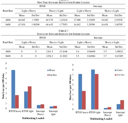
4800 0 0 1261.5 13.2686 3.6 0.96609 3.5 1.08012
1, February 2016
loss for the RTOS in heavy-loaded is 7.2% data whereas the Interrupt in the same loaded has data loss of 0.3% of data. In light loaded experiment, the average data loss for the RTOS is 8.1% data and the Interrupt is 1.1% data.
Table 6 shows experiment results of ping ti-me scenario in hybrid loaded task. Ping titi-me results show that light loaded task combined with heavy loaded task in interrupt method is the best in all baud rate. In details, if transmitter is light-loaded and the receiver is heavy-loaded then the ping time is faster than in reverse configuration. This result occurred because communication perf-ormance fo-llows the heaviest side of the system, in this case is heavy-loaded side. Because of that, performance in hybrid configuration is almost similar for each configuration. However, just like the previous sce-nario, RTOS in heavy-loaded conf-iguration gives the worst result. From these results, we can say that both cases is not good for RTOS. However, RTOS in heavy loaded task combined with light loaded task gives the best standard deviation in all baud rate.
Table VII shows experiment results of data loss scenario in hybrid loaded task. The results sh-ow us that RTOS in light loaded combined with heavy loaded task gives the best performance with no loss of data. In contrary, RTOS in heavy loaded combined with light loaded task gives the worst performance with more than 1000 data loss. Recei-ved data from RTOS with heavy loaded task will be responded quickly in RTOS with light loaded ta-sk due to there is no other tata-sk interfere. Because of that, each response in RTOS with light-loaded configuration will be counted as data res-ponse and it will made data loss in the system. In contrary, transmitted data from RTOS with light loaded task will be responded slowly in RTOS with heavy load-ed task due to there are many tasks pro-cessload-ed in the system. So, RTOS with light loaded task will be waiting data response from RTOS with heavy load-ed task and it made no loss of data. From Table 7, the Interrupt shows stable performan-ce with just 3.5 data loss in every baud rate and light-heavy lo-ad hybrid systems.
4. Conclusion
Inter-microcontroller communication is one of the crucial aspects in embedded systems. To do fast and reliable communication, the system have to manage its resources and do a simultaneus proces-ses without interfering another tasks. Methods that can be used to manage the microcontroller’s reso-urces are Interrupt Service Routine (ISR) and Real Time Operating System. Interrupt and RTOS have different system workflows, so they have their own advantages and disadvantages.
From experiments conducted in this research, the results show that interrupt and RTOS give a competitive performance, either in communication speed and data reliability. In details, interrupt give better result in speed and data reliability than RTOS if loaded with many tasks. However, if the task load is minimum, RTOS give the best result in term of speed but still lose in data reliability. It is because each task in RTOS assigned its resource to the main CPU, so If the system contains combined task load (heavy-loaded board connected with light-loaded board), interrupt is the most stable system form speed and reliability. Specific in RTOS, data loss of the system which placed heavy system as trans-mitter will give the worst result, but in vice versa it give the best data accuracy.
In the end, speed and reliability of multi-task-ing system to conduct inter-microcontroller com-munication depends on the task load of the system. Interrupt give better if the system want to focus on communication. However, interrupt only can han-dle a small amount of tasks because the limited am-ount of available timer cam-ounter register. If the main purpose of the system is to run a large amount of tasks, then RTOS is recommended.
Acknowledgement
This work was supported by Directorate Research of Universitas Indonesia funding in 2015. The title of the research is Laboratory Infra-structure. This grant number is 1831/UN2.R12/ HKP.05.00/2015. References
[1] M. Nanda, S. Dhagem and J.Jayathi, "An Approach to Formally Qualify Commercial RTOS for Safety Application," in Internatio-nal Conference on Computing for Sustain-able Global Development, 2015.
[2] Y. Hwang, G. Schirner, S. Abdi and D. G. Gajski, "Accurate Timed RTOS Model for Transaction Level Modeling," in Design, Au-tomation & Test in Europe Conference & Ex-hibition (DATE), 2010.
[3] S.L. TAN and T. N. B. Anh, "Real-time ope-rating system (RTOS) for small (16-bit) mic-rocontroller," in The 13th IEEE International Symposium on Consumer Electronics (ISCE 2009), 2009.
[4] J. C. Maeng, J.-H. Kim and M. Ryu, "An RTOS API Translator for Model-driven Em-bedded Software Development," in the 12th IEEE International Conference on Embed-ded and Real-Time Computing System and Applications, 2006.
Marcon and A. A. Susin, "Abstract RTOS Modelling for Embedded Systems," in the 15th IEEE International Workshop on Rapid System Prototyping, 2004.
[6] D. M. Purnomo, M. R. Alhamidi, G. Jati, N. Habibie, B. Hardjono and A. Wibisono, "Comparative Study of RTOS And Primitive Interrupt In Embedded System," Jurnal Ilmu Komputer dan Informasi Volumne 8 Issue 1,
pp. 36-45, 2015.
[7] T. Inc, "Techopedia," 2016. [Online]. Avail-able: https://www.techopedia.com/definition /2452/ping.
[8] R. Barry and R. T. E. Ltd, "Free RTOS," 2016. [Online]. Available: http://www.free rtos .org.
[9] R. Barry and R. T. E. Ltd, "RTOS Task Prio-rity," 2016. [Online]. Available: http:// www. freertos.org/RTOS-task-priority.html. [10] A. Corp, "Atmel 8155D AVR Atmega 32A
Datasheet," Atmel, 2014.
[11] Yuriykulikov, "FreeRTOS On XMEGA," 2012. [Online]. Available: https://github.com /yuriykulikov/FreeRTOS-on-XMEGA. [12] Arduino, "Timer," 2016. [Online]. Available: