Scalable IP Networks
Scalable IP Networks
West Sussex PO19 8SQ, England
Telephone (+44) 1243 779777
Email (for orders and customer service enquiries): [email protected] Visit our Home Page on www.wileyeurope.com or www.wiley.com
All Rights Reserved. No part of this publication may be reproduced, stored in a retrieval system or transmitted in any form or by any means, electronic, mechanical, photocopying, recording, scanning or otherwise, except under the terms of the Copyright, Designs and Patents Act 1988 or under the terms of a licence issued by the Copyright Licensing Agency Ltd, 90 Tottenham Court Road, London W1T 4LP, UK, without the permission in writing of the Publisher. Requests to the Publisher should be addressed to the Permissions Department, John Wiley & Sons Ltd, The Atrium, Southern Gate, Chichester, West Sussex PO19 8SQ, England, or emailed to [email protected], or faxed to (+44) 1243 770620.
This publication is designed to provide accurate and authoritative information in regard to the subject matter covered. It is sold on the understanding that the Publisher is not engaged in rendering professional services. If professional advice or other expert assistance is required, the services of a competent professional should be sought.
Other Wiley Editorial Offices
John Wiley & Sons Inc., 111 River Street, Hoboken, NJ 07030, USA
Jossey-Bass, 989 Market Street, San Francisco, CA 94103-1741, USA
Wiley-VCH Verlag GmbH, Boschstr. 12, D-69469 Weinheim, Germany
John Wiley & Sons Australia Ltd, 33 Park Road, Milton, Queensland 4064, Australia
John Wiley & Sons (Asia) Pte Ltd, 2 Clementi Loop #02-01, Jin Xing Distripark, Singapore 129809
John Wiley & Sons Canada Ltd, 22 Worcester Road, Etobicoke, Ontario, Canada M9W 1L1
Wiley also publishes its books in a variety of electronic formats. Some content that appears in print may not be available in electronic books.
Library of Congress Cataloging-in-Publication Data
Davies, Guy.
Designing & developing scalable IP networks / Guy Davies. p. cm.
Includes bibliographical references and index. ISBN 0-470-86739-6 (cloth : alk. paper)
1. Computer networks—Design and construction. 2. Computer networks—Scalability. I. Title: Designing and developing scalable IP networks. II. Title.
TK5105.5.D3794 2004 004.6′2—dc22
2004011563
British Library Cataloguing in Publication Data
A catalogue record for this book is available from the British Library
ISBN 0-470-86739-6
List of Figures xi
List of Tables xiii
About the Author xv
Acknowledgements xvii
Abbreviations xix
Introduction xxv
1 Hardware Design 1
1.1 Separation of Routing and Forwarding Functionality 2
1.2 Building Blocks 2
1.2.1 Control Module 3
1.2.2 Forwarding Module 3
1.2.3 Non-Stop Forwarding 3
1.2.4 Stateful Failover 3
1.3 To Flow or Not to Flow? 4
1.4 Hardware Redundancy, Single Chassis or Multi Chassis 5
2 Transport Media 7
2.1 Maximum Transmission Unit (MTU) 7
2.1.1 Path MTU Discovery 8
2.1.2 Port Density 8
2.2 Ethernet 9 2.2.1 Address Resolution Protocol (ARP) 10
2.2.2 MTU 11
2.3 Asynchronous Transfer Mode (ATM) 11
2.4 Packet Over SONET (POS) 13
2.5 SRP/RPR and DPT 13
2.5.1 Intelligent Protection Switching 15
2.6 (Fractional) E1/T1/E3/T3 16
2.7 Wireless Transport 17
2.7.1 Regulatory Constraints 17
2.7.2 Interference 17
2.7.3 Obstructions 17
2.7.4 Atmospheric Conditions 18
2.7.5 If it is so bad . . . 18
3 Router and Network Management 21
3.1 The Importance of an Out-Of-Band (OOB) Network 21
3.1.1 Management Ethernet 22
3.1.2 Console Port 22
3.1.3 Auxiliary (Aux) Port 22
3.1.4 Remote Power Management 23
3.1.5 Uninterruptible Power Supplies (UPS) 23
3.2 Network Time Protocol (NTP) 23
3.3 Logging 24
3.4 Simple Network Management Protocol (SNMP) 24
3.4.1 SNMPv1, v2c and v3 25
3.5 Remote Monitoring (RMON) 26
3.6 Network Management Systems 26
3.6.1 CiscoWorks 26
3.6.2 JUNOScope 27
3.6.3 Non-Proprietary Systems 27
3.7 Configuration Management 27
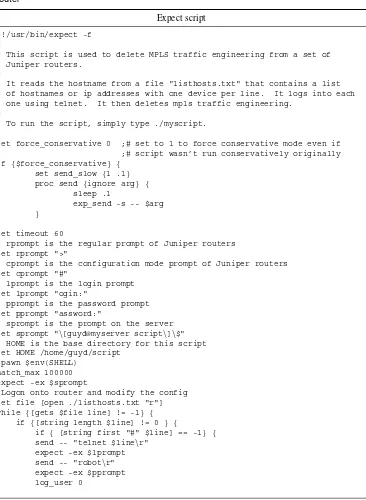
3.7.1 Concurrent Version System (CVS) 27 3.7.2 Scripting and Other Automated Configuration Distribution and
Storage Mechanisms 28
3.8 To Upgrade or Not to Upgrade 31
3.8.1 Software Release Cycles 32
3.9 Capacity Planning Techniques 32
4 Network Security 35
4.1 Securing Access to Your Network Devices 35
4.1.1 Physical Security 36
4.2 Securing Access to the Network Infrastructure 40 4.2.1 Authentication of Users, Hosts and Servers 40
4.2.2 Encryption of Information 40
4.2.3 Access Tools and Protocols 41
4.2.4 IP Security (IPsec) 43
4.2.5 Access Control Lists 44
4.2.6 RFC 1918 Addresses 45
4.2.7 Preventing and Tracing Denial of Service (DoS) Attacks 46 4.3 Protecting Your Own and Others’ Network Devices 47
5 Routing Protocols 49
5.1 Why Different Routing Protocols? 50
5.2 Interior Gateway Protocols (IGP) 50
5.2.1 Open Shortest Path First (OSPF) 51
5.2.2 Authentication of OSPF 53
5.2.3 Stub Areas, Not So Stubby Areas (NSSA) and Totally Stubby
Areas 54
5.2.4 OSPF Graceful Restart 55
5.2.5 OSPFv3 56
5.2.6 Intermediate System to Intermediate System (IS-IS) 56
5.2.7 Authentication of IS-IS 57
5.2.8 IS-IS Graceful Restart 58
5.2.9 Routing Information Protocol (RIP) 58 5.2.10 Interior Gateway Routing Protocol (IGRP) and Enhanced Interior
Gateway Routing Protocol (EIGRP) 59
5.2.11 Diffusing Update Algorithm (DUAL) 61
5.2.12 Stuck-in-Active 62
5.2.13 Why use EIGRP? 62
5.3 Exterior Protocols 63
5.3.1 Border Gateway Protocol (BGP) 63
5.3.2 Authentication of BGP 67
5.3.3 BGP Graceful Restart 68
5.3.4 Multiprotocol BGP 69
6 Routing Policy 71
6.1 What is Policy For? 71
6.1.1 Who Pays Whom? 72
6.2 Implementing Scalable Routing Policies 72
6.3 How is Policy Evaluated? 73
6.3.1 AND or OR? 73
6.3.2 The Flow of Policy Evaluation 73
6.4 Policy Matches 74
6.5.1 The Default Action 74 6.5.2 Accept/Permit, Reject/Deny, and Discard 74
6.6 Policy Elements 75
6.7 AS Paths 75
6.8 Prefix Lists and Route Lists 75
6.9 Internet Routing Registries 77
6.10 Communities 78
6.11 Multi-Exit Discriminator (MED) 80
6.12 Local Preference 80
6.13 Damping 81
6.14 Unicast Reverse Path Forwarding 83
6.15 Policy Routing/Filter-Based Forwarding 84
6.16 Policy Recommendations 84
6.16.1 Policy Recommendations for Customer Connections 84 6.16.2 Policy Recommendations for Peering Connections 85 6.16.3 Policy Recommendations for Transit Connections 85
6.17 Side Effects of Policy 91
7 Multiprotocol Label Switching (MPLS) 97
7.1 Traffic Engineering 98
7.2 Label Distribution Protocols 99
7.3 Tag Distribution Protocol (TDP) 100
7.4 Label Distribution Protocol (LDP) 100
7.4.1 LDP Graceful Restart 101
7.5 RSVP with Traffic Engineering Extensions (RSVP-TE) 101
7.5.1 RSVP-TE Graceful Restart 102
7.5.2 OSPF with Traffic Engineering Extensions (OSPF-TE) 102 7.5.3 IS-IS with Traffic Engineering Extensions (IS-IS-TE) 102
7.6 Fast Reroute 103
7.7 Integrating ATM and IP Networks 104
7.8 Generalized MPLS (GMPLS) 105
8 Virtual Private Networks (VPNs) 109
8.1 VPNs at Layer 3 109
8.1.1 Layer 3 VPN (RFC 2547bis) 109
8.1.2 Generic Router Encapsulation (GRE) 111
8.1.3 IPsec 112
8.2 VPNs at Layer 2 112
8.2.1 Circuit Cross-Connect (CCC) 112
8.2.2 Translational Cross-Connect (TCC) 113
8.2.3 Martini (Layer 2 circuits) 113
9 Class of Service and Quality of Service 119
9.1 Design and Architectural Issues of CoS/QoS 119
9.2 CoS/QoS Functional Elements 120
9.2.1 Classification 120
9.2.2 Congestion Notification Mechanisms 121 9.2.3 Congestion Avoidance Mechanisms 122
9.2.4 Queueing Strategies 124
9.3 QoS Marking Mechanisms 127
9.3.1 Layer 2 Marking 128
9.3.2 Layer 3 QoS 129
9.3.3 MPLS EXP 130
9.4 Integrating QoS at Layer 2, in IP and in MPLS 130 9.4.1 DiffServ Integration with MPLS 131
10 Multicast 133
10.1 Multicast Forwarding at Layer 2 133
10.1.1 Multicast on Ethernet and FDDI 134
10.1.2 Multicast Over Token Ring 134
10.1.3 Internet Group Management Protocol (IGMP) 135
10.1.4 IGMP Snooping 136
10.1.5 PIM/DVMRP Snooping 136
10.1.6 Immediate Leave Processing 137
10.1.7 Cisco Group Management Protocol (CGMP) 137
10.2 Multicast Routing 138
10.2.1 Reverse Path Forwarding (RPF) Check 138
10.2.2 Dense Mode Protocols 138
10.2.3 Sparse Mode Protocols 143
10.2.4 Multicast Source Discovery Protocol (MSDP) 148
10.2.5 Multiprotocol BGP 149
10.2.6 Multicast Scoping 149
11 IPv6 153
11.1 Evolution and Revolution 153
11.2 IPv6 Headers 154
11.3 IPv6 Addressing 154
11.3.1 Hierarchical Allocations 155
11.3.2 Address Classes 157
11.4 Stateless Autoconfiguration 158
11.5 Domain Name System (DNS) 158
11.6 Transition Mechanisms 159
11.6.1 Dual Stack 159
11.6.2 Network Address Translation—Protocol Translation 159
11.7 Routing in IPv6 161
11.7.1 IS-IS for IPv6 161
11.7.2 OSPFv3 161
11.7.3 RIPng 161
11.7.4 Multiprotocol BGP 162
11.8 Multicast in IPv6 162
11.9 IPv6 Security 162
11.10 Mobility in IPv6 163
12 Complete Example Configuration Files (IOS and JUNOS Software) 165
12.1 Core Router (P) Running MPLS TE Supporting LDP Tunnelled Through RSVP-TE, No Edge Interfaces, iBGP Only, Multicast RP (Anycast
Static) MSDP, PIM-SM (JUNOS) 166
12.2 Core Router (P) Running MPLS TE Supporting LDP Tunnelled Through RSVP-TE, No Edge Interfaces, iBGP Only, Multicast RP (Anycast
Static) MSDP, PIM-SM (IOS) 183
12.3 Aggregation Router (PE) Running MPLS L3 and L2VPN Over LDP,
BGP Policy to Customers, MBGP, PIM-SM (JUNOS) 192 12.4 Aggregation Router (PE) Running MPLS L3 and L2VPN Over LDP,
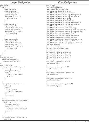
BGP Policy to Customers, MBGP, PIM-SM (IOS) 213 12.5 Border Router Running MPLS with LDP, BGP Policy to Peers, MBGP,
PIM-SM (JUNOS) 222
12.6 Border Router Running MPLS with LDP, BGP Policy to Peers, MBGP,
PIM-SM (IOS) 236
12.7 Transit Router Running MPLS with LDP, BGP Policy to Upstream
Transit Providers, MBGP, PIM-SM (JUNOS) 242 12.8 Transit Router Running MPLS with LDP, BGP Policy to Upstream
Transit Providers, MBGP, PIM-SM (IOS) 257
References 263
1.1 The logical architecture of an IP router (separate forwarding and routing planes)
2.1 Overhead associated with the transport of IP packets in ATM cells 2.2 Intact SRP dual counter rotating rings
2.3 Both fibres cut at a single point, ring wrapped at adjacent nodes 2.4 Node lost, ring wrapped at adjacent nodes
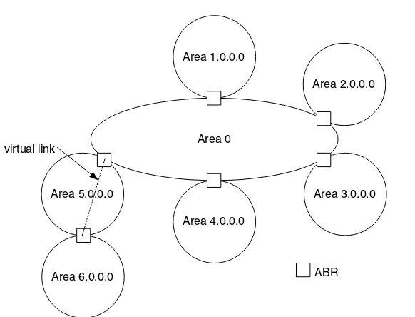
4.1 Security Associations unidirectional 5.1 Multi-area OSPF hierarchy
5.2 Illegal OSPF hierarchy
5.3 A virtual link makes this hierarchy legal 5.4 Route reflection
5.5 BGP confederations
6.1 Example network for persistent oscillation 7.1 MPLS label
7.2 Traffic engineering with MPLS 7.3 MPLS fast reroute, link protection 7.4 MPLS fast reroute, node protection 7.5 Integrating MPLS and ATM networks
7.6 Integrating MPLS and Optical switches with GMPLS 8.1 MPLS Layer 3 VPN example
8.2 MPLS Layer 3 VPN example using route reflection 8.3 VPLS example
9.1 Global TCP synchronization 9.2 Output with RED applied
10.1 Example multicast network
10.2 Example of the limitations of TTL-based multicast scoping
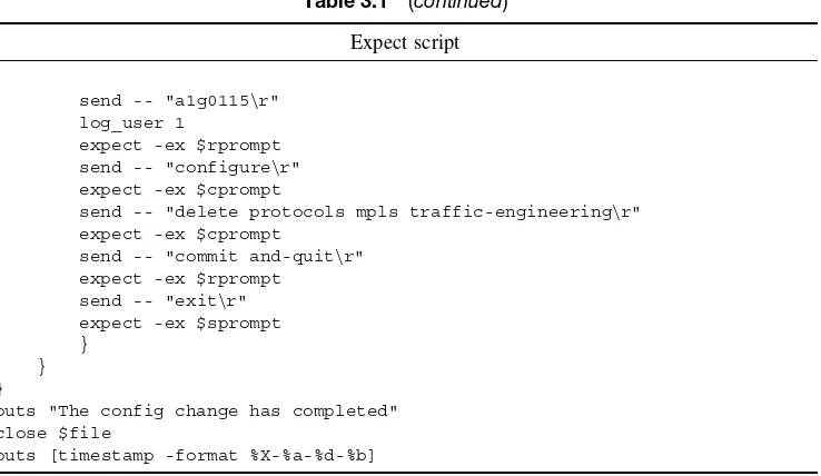
3.1 Expect script to delete MPLS traffic engineering configuration from a Juniper router
3.2 Perl script to delete MPLS traffic engineering configuration from a Juniper router
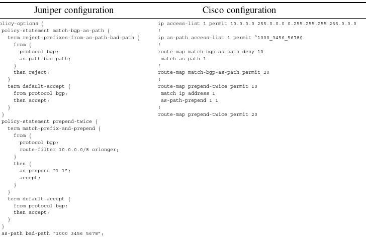
6.1 Comparison of verbose and terse configuration style 6.2 JUNOS and IOS BGP policy configuration format 6.3 JUNOS prefix list.
6.4 IOS prefix list 6.5 JUNOS firewall filters 6.6 IOS access lists
6.7 Using BGP communities with JUNOS and IOS
6.8 Configuring BGP route flap damping with JUNOS and IOS
6.9 Limited sample BGP configuration to customers using JUNOS and IOS 6.10 Limited sample BGP configurations to peers using JUNOS and IOS 6.11 Limited sample BGP configurations to transit providers using JUNOS and
IOS
6.12 Initial routing state in cluster 1 6.13 Initial routing state in cluster 2 6.14 Modified routing state in cluster 1 6.15 Modified routing state in cluster 2
6.16 Comparison of the active route selection processes in JUNOS and IOS 7.1 IOS configuration to constrain LDP advertisements to loopback0 only 9.1 Mappings from IP ToS bits settings to output queuers using four output
Guy Davies has worked as an IP Architect for Telindus, a network integrator in the UK, for four years. While at Telindus, he has been involved in many projects ranging from the design, implementation and operation of customers’ core IP networks through to migration of ATM networks to an IP and MPLS-based infrastructure, and the design and implementation of large secured wireless networks and consultancy as well as the development of wireless rural broadband access. During this time, he has also worked as a contractor to Juniper Networks, providing engineering and consulting services both in the UK and overseas.
Prior to Telindus, Guy spent five years working for UUNET (and its previous incarna-tion in the UK, PIPEX). During his time at PIPEX and UUNET, Guy worked in a variety of engineering and management roles including systems administration, network opera-tion and development roles. He was responsible for the design of the first pan-European MPLS core network built by UUNET.
Guy is JNCIE #20 and is also a CCIP.
BIOGRAPHY OF REVIEWER
This book has just one author. Despite that, it is only through the efforts of a number of people that this book has now been published.
I would first of all like to thank Patrick Ames. It was he who convinced me to write this book in the first place. Then, having got me to put my ideas down, it was he who helped me find a publisher for my work and he who kept me going, even when I doubted my own ability to complete the project. Without a doubt, this book would not have seen the light of day but for him.
Throughout the writing process, I have received corrections and advice from an array of friends and colleagues. Several engineers and consultants at Juniper Networks provided significant input. Particular thanks go to Aviva Garrett, Paul Goyette, Pete Moyer, Bill Nowak and Todd Regonini, who all provided invaluable technical information. I thank my former colleagues at UUNET, Tony Barber and John Whyte, for their thorough technical review and discussion of various issues covered in the book. I’d also like to thank Danny McPherson, who provided some useful insight into several issues surrounding BGP and the selection of parameters for policy. In addition to the technical reviewers above, Cressi Whyte gave some extremely useful advice on writing style.
I also received great help from Richard Southern of Juniper TAC in checking the config-urations at the end of this book. I greatly appreciate the help he gave me at exceptionally short notice. Despite the time constraints, his work was thorough and accurate.
I would also like to thank the editing team at John Wiley & Sons, Ltd: Sally Mortimore, Birgit Gruber, Daniel Gill, Susan Dunsmore and Lucy Bryan.
AAA Authorization, Authentication and Accounting AAL ATM Adaption Layer
ABR Area Border Router ABR Available Bit Rate
AES Advanced Encryption Standard AH Authentication Headers
APS Automatic Protection Switching ARP Address Resolution Protocol AS Autonomous System
ASIC Application Specific Integrated Circuit ASM Any Source Multicast
ATM Asynchronous Transfer Mode BA Behaviour Aggregate
BECN Backward Explicit Congestion Notification BFWA Broadband Fixed Wireless Access
BGP Border Gateway Protocol BSR Bootstrap Router
CA Certificate Authority CBR Constant Bit Rate
C-BSR Candidate Bootstrap Router CCC Circuit Cross Connect CE Customer Edge LSR/Router CGMP Cisco Group Management Protocol CIDR Classless Inter-Domain Routing CLI Command Line Interface
CLNP Connectionless Network Protocol CoS Class of Service
C-RP Candidate Rendezvous Point
CSMA-CD Carrier Sense Multiple Access-Collision Detection CSPF Constrained Shortest Path First
CVS Concurrent Version System DCE Data Communication Equipment DCN Data Control Network
DE Discard Eligible DNS Domain Name System DoS Denial of Service
DPT Dynamic Packet Transport DR Designated Router DRR Deficit Round Robin DSCP DiffServ Code Point
DTE Data Terminating Equipment DUAL Diffusing Update Algorithm
DVMRP Distance Vector Multicast Routing Protocol DWDM Dense Wavelength Division Multiplexing EAP Extensible Authentication Protocol ECN Explicit Congestion Notification ECT ECN Capable Transport
EIGRP Enhanced Interior Gateway Routing Protocol
E-LSP Diffserv integrated LSP using EXP bits to represent DSCP ESP Encapsulating Security Payload
EXP MPLS Experimental Bits FC Feasibility Condition FD Feasibility Distance
FEC Forwarding Equivalence Class
FECN Forward Explicit Congestion Notification FSC Fibre Switched Capable
FT Fault Tolerant TLV FTP File Transfer Protocol GDA Group Destination Address
GMPLS Generalized Multiprotocol Label Switching GPRS General Packet Radio Service
GPS Generalized Packet Scheduler GRE Generic Router Encapsulation ICMP Internet Control Message Protocol
IEEE Institute of Electrical and Electronic Engineers IETF Internet Engineering Task Force
IGMP Internet Group Management Protocol IGP Interior Gateway Protocol
IGRP Interior Gateway Routing Protocol IIH IS-IS Hello PDU
IPS Intelligent Protection Switching IRR Internet Routing Registry IS Intermediate System
IS-IS Intermediate System to Intermediate System ISO International Organization for Standardization IXP Internet Exchange Point
L2TP Layer 2 Tunneling Protocol LDP Label Distribution Protocol LIR Local Internet Registry
L-LSP Diffserv integrated LSP using labels to represent different DSCP LOL Loss Of Light
LOS Loss Of Signal
LSA Link State Advertisement LSC Lambda Switched Capable LSDB Link State Database
LSP Label Switched Path (MPLS) LSP Link State PDU (IS-IS) LSR Label Switching Router MAC Media Access Control
MBGP Multiprotocol Border Gateway Protocol MD5 Message Digest 5
MED Multi-Exit Discriminator MIB Management Information Base MPLS Multiprotocol Label Switching MRU Maximum Receive Unit
MSDP Multicast Source Discovery Protocol MSP Multiplex Section Protection
MTU Maximum Transmission Unit NAS Network Access Server NAT Network Address Translation
NLRI Network Layer Reachability Information NSSA Not-So-Stubby Area
NTP Network Time Protocol OCn Optical Carrier ‘times n’ OID Object Identifier
OOB Out Of Band
OSI Open System Interconnection OSPF Open Shortest Path First P Provider LSR (core LSR) PCR Peak Cell Rate
PDU Protocol Data Unit
PE Provider Edge LSR (aggregation LSR) PHB Per Hop Behaviour
PIM-SM Protocol Independent Multicast Sparse Mode PKI Public Key Infrastructure
PMTU-D Path MTU Discovery PoP Point of Presence
POS Packet over SONET/SDH PSC Packet Switched Capable
PSTN Public Switched Telephone Network QoS Quality of Service
RADIUS Remote Authentication Dial-In User Service RED Random Early Detect or Random Early Discard RIB Routing Information Base
RIP Routing Information Protocol
RIPE R´eseaux IP Europ´eens (The RIR for Europe, the Middle East and parts of Africa)
RIR Regional Internet Registry RMON Remote Monitoring MIB RP Rendezvous Point RPF Reverse Path Forwarding RPR Redundant Packet Ring RPT Rendezvous Path Tree RR Route Reflector
RSN Robust Security Network RSVP resource ReSerVation Protocol RSVP-TE RSVP with TE extension RTP Reliable Transport Protocol SA Security Association
SAR Segmentation And Reassembly SCR Sustained Cell Rate
SDH Synchronous Digital Hierarchy SLA Service Level Agreement
SNMP Simple Network Management Protocol SONET Synchronous Optical Network
SPF Shortest Path First
SPI Security Parameter Identifier SPT Source Path Tree
SRP Spatial Reuse Protocol SSH Secure Shell
SSL Secure Sockets Layer SSM Source Specific Multicast
STM-n Synchronous Transport Module ‘times n’
TACACS Terminal Access Controller Access Control System TCP Transmission Control Protocol
TE Traffic Engineering
TED Traffic Engineering Database telco Telephone Company
TFTP Trivial File Transfer Protocol TKIP Temporal Key Integrity Protocol TLS Transport Layer Security TLV Type/Length/Value ToS Type of Service
TSC Time Division Multiplexing (TDM) Switched Capable TTL Time To Live
UBR Unspecified Bit Rate
UMTS Universal Mobile Telecommunications System USA Unicast Source Address
VBR-NRT Non-Real Time Variable Bit Rate VBR-RT Real Time Variable Bit Rate VPLS Virtual Private LAN Service VPN Virtual Private Network VPWS Virtual Private Wire Service
VRF Virtual Routing and Forwarding Table VSA Vendor Specific Attribute
Today’s Service Provider (SP) marketplace is a highly competitive environment in which it is important to make the most of the assets you have. The halcyon days of the late 1990s, when providers had vast amounts of money to spend on equipment and transmission services and spent it at a prodigious rate, are long gone. It is essential that network architects today can design IP and MPLS networks, which are flexible enough to expand and, possibly more importantly, can cope with new and profitable services being added to the network.
WHAT IS THIS BOOK ALL ABOUT?
As a network engineer working and learning my job in the mid-1990s I often wished I had a book that would help me understand the decisions being made by our design and development team. I wanted to join that team and, if I was to design scalable networks for my employer, I needed to have that understanding. Unfortunately, no such book existed. There were a number of books describing the operation and behaviour of various IP routing protocols (useful resources in themselves) but none which explained the principles of how to build and operate large networks. I was extremely fortunate to be able to learn from other more senior members of the various engineering groups and this book is the amalgamation of what I was taught and what I have learned through self-study and painful experience.
This book will not provide in-depth descriptions of the protocols associated with IP routing and switching. For those seeking an in-depth treatment of those protocols, there are a number of other books that provide an excellent reference (e.g. Routing TCP/IP, Volume 1 by Jeff Doyle,Routing TCP/IP, Volume 2 by Jeff Doyle and Jennifer Carroll, and Complete Reference: Juniper Networks Routers by Jeff Doyle and Matt Kolon).1
There will be detailed discussion, where necessary, to explain the way particular features and protocol behaviours impact the scalability of a network.
WHO IS THIS BOOK FOR?
This book is intended to provide a guide to those designing IP networks. It will pro-vide both a guide and a reference to network architects and engineers. In addition to those designing networks, it will also be useful to network operations staff who want to understand some of the principles being applied in the architecture and design of their network.
It is also hoped that this book will provide a valuable resource for people studying for the CCIE and JNCIE exams from Cisco Systems and Juniper Networks, respectively. While design does not actually form part of those exams, a solid understanding of the design process can only be beneficial to candidates. Also, while not referring directly to any other vendors’ software or hardware, the principles described herein should be applicable to designing or building a network using any vendor’s equipment.
While this book focuses on processes and mechanisms with respect to the design of service provider networks, much of the material in this book can be applied to the design of any IP network, irrespective of whether it is a service provider’s network or an enterprise’s network.
It is assumed that the reader is familiar with the basic principles of IP networking and the protocols associated with IP routing and switching.
SCALING: GETTING BIGGER AND DOING MORE
Scaling means different things to different people. Most will agree that it means getting bigger. Getting bigger is certainly an extremely important issue but it is important that in order to grow, it is not necessary to entirely redesign the architecture of your network. The initial design of your network will dictate how easily you can make subsequent changes.
1Jeff DoyleRouting TCP/IP, Volume 1, Cisco Press, ISBN 1578500418. Jeff Doyle and Jennifer
In addition, it is important to recognize that scaling does not just mean building bigger networks but also means being able to offer a wider range of services to your customers using your existing assets. In today’s marketplace, it is no longer sufficient to provide a network that provides simple IP access. Customers are demanding new and different services (e.g. VPNs, CoS/QoS-backed SLAs, etc.). The ability to add new services to your network will be pivotal to your potential to grow your business and maintain (or move into) profitability.
DESIGNING A NETWORK FROM SCRATCH
Few of us are lucky enough to have the luxury of designing a network from scratch. For those of us who are, there are opportunities that are not available when trying to enlarge or extend the functionality of an existing network. In a new network it is possible, within financial constraints, ‘to do the right thing’. For example, it is possible to create efficient IP addressing and efficient aggregation schemes. This can significantly reduce the size of the routing tables in all your routers. In hierarchical routing models in which the core routers see all routes, this is particularly important. Reducing the size of your routing tables has a positive impact not only on the memory required to maintain them but also on the processing power required to calculate routing updates.
SCALING AN EXISTING NETWORK
In the previous section, it was pointed out how much easier it is to start from scratch. However, that does not mean that it is not possible to achieve great improvements in scalability in an existing network. When scaling an existing network, you will have to deal with decisions you may have made earlier and, often more significantly, decisions made by your colleagues and predecessors. It is sometimes possible to reverse decisions but, more often than not, you will have to work within the constraints they impose.
FUNCTIONAL ELEMENTS OF SP NETWORKS
ADM
ADM
AS101
AS303 AS202
AS101
AS505
AS606
AS2000 AS1000
AS5555 AS6666
Figure I.1 Example network used in this book
SPs and every possible workaround to almost every possible problem has been tried on someone’s network.
Throughout this book, we will be providing a number of examples. These will demon-strate aspects of scalability across the various functional elements of service provider networks. In order to do this, we will be using a single consistent network or autonomous system. This is shown in Figure I.1.
TERMS USED IN THIS BOOK
Various terms are used throughout this book to describe the different functional elements of SP networks. The terms used throughout this book are described below.
Some SPs also use a further layer of distribution devices, perhaps to aggregate traffic from a regional network into the core or to aggregate traffic from particular types of access devices (e.g. CMTS) into the core.
• Access (Provider Edge/PE). An access or edge switch/router is a device that provides connectivity between customer edge (CE) router on customer networks and the SP core network.
• Fixed access. Fixed access refers to all access provided over fixed transport media. This includes leased lines (E1/T1, E3/DS-3, STM-x/OCy), metro Ethernet, fiber to
the home/curb, etc.
• Broadband (Cable/DSL). Technically, this is a subsection of the previous section since almost all broadband services are currently provided over fixed lines (cable or telephone lines). There are, however, some wireless DSL services. However, there are particular aspects of these access methods, which require specific consideration.
• Wireless. This covers all forms of non-fixed access (GPRS/UMTS, WLAN, BFWA, etc). Wireless access presents a number of specific problems associated with security, capacity and reliability.
• Border (Provider Edge/PE). This is a switch/router that is somewhat like an access device. However, it provides access to other provider networks rather than to customer networks. This is a small but incredibly important difference and has a major impact on the configuration requirements.
• Peer networks. Peer switch/routers are border devices that connect your network to peer networks. Peer networks are other provider networks with which you want to exchange routing information while sharing the cost of the connection. No money normally changes hands between the operators of networks with a peering relation-ship.
• Transit. Transit switch/routers are border devices that connect your network to your upstream transit provider. Transit providers are other provider networks, which pro-vide connectivity to the Internet or, in some cases, a particular region (e.g. Europe, America, Asia). This is a customer/provider relationship and the transit provider will charge a fee for this service.
• Customer Edge (CE). This is a switch/router that provides connectivity between a customer network and the PE on a SP network. In some respects, the Transit PE described above could be viewed as a CE device. As far as the transit provider PE is concerned, that router is a CE.
ORGANIZATION OF THIS BOOK
CHAPTER 1 HARDWARE DESIGN
In this chapter, I will take a look at some of the different choices made by hardware vendors in the design of their equipment and how each of their choices might impact the scalability of your network. It might seem at first that this is entirely out of your hands. However, an understanding of the architecture of vendors’ equipment can be exceptionally useful in enabling you to scale your IP network.
CHAPTER 2 TRANSPORT MEDIA
This chapter looks at the various transport media available and evaluates the impact on scalability of each of them. Different media have significantly differing levels of overhead just in the transportation of the packets. They also impose different loads on the network in respect of maintaining the link. It is also important to note that the routing protocols you choose and their behaviours may influence your chosen transport media, and vice versa. Routing protocols are discussed in Chapter 5.
CHAPTER 3 ROUTER AND NETWORK MANAGEMENT
This is an area which is often overlooked but can dramatically affect the administrative effort required to operate your network as it grows. Having the tools to understand and modify the behaviour of your network is essential. The greater your understanding, the more accurate your ability to modify your network behaviour.
CHAPTER 4 NETWORK SECURITY
Security is clearly a significant issue for all networks, large or small. As your network grows, the security issues become bigger. It is also an unfortunate fact of life that the frequency, variety and impact of attacks have grown significantly over the past few years. The details of these attacks are often made public and implementations published on the Internet. This makes it easy for anyone with the inclination to (effectively anonymously) mount an attack on your network from hundreds or even thousands of globally distributed sources. The proliferation of ‘always on’ connections to home users has provided these attackers with millions of potential targets and sources.
CHAPTER 5 ROUTING PROTOCOLS
This chapter covers all the main unicast routing protocols used in SP networks today. The scalability of your network is fundamentally reliant upon the scalability of your chosen routing protocols and, equally importantly, on the way in which you configure them. No matter how excellent the inherent scalability of the routing protocols you use, if you configure them poorly, your network will not scale, in any sense of the word.
CHAPTER 6 ROUTING POLICY
Routing policy is the technical means by which you implement your business policies with respect to your customers, peers and transit providers. As with the routing protocols themselves, it is critical that you develop effective routing policy to assist you in scaling your network.
CHAPTER 7 MULTIPROTOCOL LABEL SWITCHING (MPLS)
Multiprotocol label switching was initially devised as a means of improving the speed of IP forwarding (actually by doing a lookup on a fixed length label rather than a variable length IP prefix) in software-based routers. As vendors built hardware (ASIC) based routers, it became clear that the lookup performance of a variable length IP prefix was equal to that of a fixed length MPLS label. No longer needed for improvements in forwarding performance, the traffic engineering capabilities of MPLS became the focus. Traffic engineering allows network operators to make more effective and efficient use of their transmission assets.
CHAPTER 8 VIRTUAL PRIVATE NETWORKS (VPNs)
One of the major ‘fashionable’ services being offered to customers is IP-based Virtual Private Networks. It is suggested that VPNs can save vast amounts of money for enter-prises when compared to the cost of private lines or even an ATM or Frame Relay-based VPN. This may indeed be the case for the enterprise but if the service is not scalable, then it is almost certain to be unprofitable and unmanageable for the service provider.
CHAPTER 9 CLASS OF SERVICE AND QUALITY OF SERVICE
Adding CoS/QoS to an IP/MPLS network is a significant undertaking. It is important to understand what customers want and it is important to strike a balance between the perfect service as perceived by customers and a realistic, scalable service from the point of view of the service provider.
CoS/QoS provides the mechanism whereby SPs can offer differentiated services for which they can charge a premium. As the number of services running over a single infras-tructure increases, so the importance of CoS/QoS increases. It is essential that best-effort traffic generated by low-paying customers must not overwhelm priority traffic generated by premium customers.
CHAPTER 10 MULTICAST
Multicast design can be a difficult thing to get right. One of the goals of multicast is to make the transmission of identical information to multiple receivers much more scalable. However, if used in the wrong circumstances or poorly implemented in your network, it can be detrimental to the overall scalability of all aspects of your network operations.
CHAPTER 11 IPv6
IPv6 is the latest version of the Internet Protocol. It has a number of enhancements over IPv4, which include improved security, improved mobility and vastly extended address space. This chapter will cover the differences between IPv4 and IPv6 including the mod-ifications to the IP frame format, routing protocols and control protocols. It will also look at how the requirements imposed by IPv6 in the future can impact your network design decisions today.
CHAPTER 12 COMPLETE EXAMPLE CONFIGURATION FILES
(IOS AND JUNOS SOFTWARE)
1
Hardware Design
Hardware design may, at first sight, seem to be something over which the network archi-tect or designer has no control. It would appear, therefore, that it plays very little part in the design of a scalable Internet Provider (IP) network. Despite this, an understand-ing of the various architectures employed by the hardware vendors can influence the choice of hardware. Thus, the choice of hardware will inevitably affect your network designs.
There are only a finite number of architectures on which hardware designs are based. Most vendors of core Internet routers today use various Application Specific Integrated Circuits (ASIC) and/or network processors designed specifically for the purpose of per-forming IP and MPLS lookups, applying access control/firewall functionality, enforcing policy and applying Quality of Service (QoS). However, there are significant differ-ences in the various implementations of architectures within the plethora of available access routers and switches. Some still rely on a software-based system with a more general-purpose processor, which provides the flexibility to add services at the expense of forwarding performance. This contrasts with ASICs, which are (as the name sug-gests) designed for a single function, or group of functions. The first generation of ASIC-based devices provided very high-speed forwarding at the cost of flexibility and services. In addition, this improved performance is gained at the cost of higher devel-opment cost and longer time to market. The introduction of network processor-based systems has combined the flexibility of a general-purpose processor without sacrific-ing any of the packet forwardsacrific-ing capabilities of an ASIC. In addition, the non-specific nature of the network processor can lead to lower costs than those associated with ASICs.
1.1
SEPARATION OF ROUTING AND FORWARDING
FUNCTIONALITY
One of the major steps forward in ensuring scalability in network performance over the past few years has been the move towards the separation of routing and forwarding functionality. Put simply, the process of calculating the forwarding table is run on different hardware from that responsible for actually implementing the packet forwarding.
By separating these functions onto different hardware modules it is possible to continue forwarding packets at line rate even in the presence of severe disruptions to the network topology. Designs based on general-purpose processors have to use processor cycles to make both the routing decisions and the forwarding decisions. Therefore, if the network topology is dramatically and repeatedly updated, the processor with a fixed number of cycles is required to take cycles from the forwarding tasks to carry out the routing tasks or vice versa.
1.2
BUILDING BLOCKS
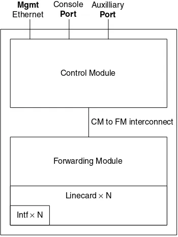
A router based on the principles of separation of routing and forwarding functionality is based on a few simple building blocks, (see Figure 1.1).
Control Module
Forwarding Module
Linecard× N
Intf× N
Mgmt
Ethernet
Auxilliary
Port
Console
Port
CM to FM interconnect
1.2.1
CONTROL MODULE
The control module is responsible for running the routing protocols, creating a routing table from the sum of the routing information received and generating a forwarding table from the routing table. This includes the enforcement of policy relative to the routing information being imported and exported. In addition to the routing function, this module provides Command Line Interface (CLI), management and logging functionality.
1.2.2
FORWARDING MODULE
The forwarding module is responsible for the receipt of packets, decoding the Layer 1, Layer 2 and Layer 3 information and sending that packet to the appropriate output inter-face (or interinter-faces in the case of multicast) where it is re-encoded with Layer 3, Layer 2 and Layer 1 information before transmission onto the wire. The forwarding module is also the ideal location for implementing access control/firewall filters and class/quality of service. ASIC and Network Processor-based devices tend to implement these features in the forwarding module. Traditional, software-based routers always had to send every packet to the CPU if any of these features were enabled. This was one of the main reasons why software-based routers were unable to implement complex services while maintaining high packet throughput.
1.2.3
NON-STOP FORWARDING
Non-stop forwarding is the generic term for the ability of a router to carry on forward-ing packets even though the device responsible for the calculation of the routforward-ing and forwarding tables is temporarily inoperable. The specific reason for the inoperability of the routing device is really of no importance at this stage of the discussion. Non-stop forwarding fundamentally relies on the separation of routing and forwarding functionality within the router. In addition, each routing protocol requires a number of modifications to the protocol operation in order to prevent the clearance of routes associated with the failed protocol from the forwarding table on the forwarding modules, both on the local router and on the neighbours of the local router, while the routing process or module recovers.
1.2.4
STATEFUL FAILOVER
There are, as usual, strongly held opinions about whether this is a good idea or not. Some vendors feel that it is foolhardy to copy all the state from the active control module to the slave. The main concern is that if a particular software bug or combination of state causes the master control module to reset and that state has been copied faithfully onto the slave, then, in all likelihood, the same problem will arise on the slave and cause it to reset. This would clearly be something of a disaster, given that the whole point of mirroring the state onto the slave control module is to prevent the total failure of the device.
On the other side of the argument, this mechanism provides the potential for the fastest failover. By maintaining an exact copy of the state from the master control module on the slave control module, it is possible to begin forwarding packets immediately without having to rebuild the routing information bases (RIB). This mechanism imposes no extra requirements upon the routing protocols to enable non-stop forwarding.
1.3
TO FLOW OR NOT TO FLOW?
This might sound like a rather bizarre question. The obvious answer is ‘of course we want the traffic to flow’. But this question does not actually relate to the flow of traffic but to the internal architecture of the network device.
Many Layer 2 switches work on flow-based mechanisms. A flow is a single stream of traffic associated with a single ‘conversation’ between two network devices. These can be uniquely identified by the source and destination address and source and destination TCP or UDP port. When the first packet for a new flow arrives, the packet is sent to the CPU and the switch creates a new entry in a flow table, which identifies the flow characteristics along with the ingress and egress ports. Once the flow entry has been created, then all subsequent traffic matching that flow is switched from the ingress to the egress port without touching the CPU, thus dramatically improving the performance. In an environment in which there are a constrained number of long-lived flows, these devices provide extremely good performance. However, if there are a large number of short-lived flows, performance becomes constrained by the ability of the CPU to create new entries in the flow table and by the amount of memory available to store the flow table. If there are too many new flows, either new ones will not be created or existing ones will have to be purged from the flow table to make way for the new ones. As soon as another packet for the purged flow arrives, it requires the set-up of a new flow. Thus, the problem is exacerbated.
As the line between Layer 2 devices and Layer 3 devices became blurred, many flow-based switches acquired Layer 3 (and Layer 4 through 7) functionality. In an enterprise environment, this is not a significant issue because flows are generally fewer in number and longer-lived. However, in a service provider there are almost invariably vast numbers of comparatively short-lived flows, particularly at major aggregated egress points. This is the worst possible situation for flow-based devices.
may be asking what the attraction of such devices was given their clear disadvantages within a service provider network. The simple answer often is cost. Switch-based routers (a.k.a. Layer 3 switches) are invariably cheaper than their traditional counterparts, some-times by a factor of three or four. They also generally have hybrid functionality so they can be used in both Layer 2 and Layer 3 roles. These advantages in terms of price and flexibility are often sufficient to convince hard-pressed service providers to try to get more for their money.
To be fair to the vendors of flow-based routers, many have enhanced their devices with much more powerful CPUs and much more memory for the flow tables. This helps to mitigate some of the problems but does not solve the inherent issues. The problem is just masked until the number of flows or rate of creation of flows grows sufficiently to overwhelm the new hardware.
One mechanism for overcoming this issue is tunnelling, since the packets are forwarded based on the outer headers, which relate only to the end points at the edge of the service provider’s network. One widely used implementation of this feature is MPLS (discussed more fully later in the book). Because tunnels or Label Switched Paths (LSPs) are built between the edge routers in the networks and all traffic between those points is carried within the LSP, it aggregates to a single ‘flow’.
Even with the enhanced devices, you should think long and hard before you use a flow-based router for a service provider network. Think particularly about the environment in which the router will be used and be sure that the performance constraints of the flow-based router will not come back and bite you.
1.4
HARDWARE REDUNDANCY, SINGLE CHASSIS
OR MULTI CHASSIS
The choice of mechanism used to provide redundancy for each function within a single network node (a.k.a. hub) usually arouses one of two generally strongly held opinions. One theory is that it is best to create a single network element in which all the major service-impacting elements are replicated. This works on the premise that you generally provide N+1 (N>=1) processing, switching, forwarding/interface, power and cooling
protocols. Fewer links and fewer nodes mean less state and fewer changes in topology. Finally, the reduced administrative and support costs of operating a single device rather than several devices can be significant.
An alternative theory is that no matter how clever the design (or how much money you spend), it is not possible to produce a single unit with sufficient resilience in all the aspects (particularly forwarding) to adequately protect customer traffic. Therefore, it is better to build a resilient function by provisioning devices in groups, so that the complete failure of a single device may lead to reduced performance but never total loss of connectivity. However, more chassis inevitably mean a greater demand for power, more real estate, more instability in the network topology and greater support costs.
As with most things, designing a network is full of compromises and what usually happens is that service providers end up implementing a combination of the two theories. Traditionally, core routers, in which the forwarding function is paramount, are often provisioned in pairs with each taking a share of the links from other core sites and each having an equal capacity into the hub. The loss of one core router, therefore, reduces the aggregate capacity into the hub but does not isolate the hub from the rest of the network. The negative side of this model is that it significantly increases complexity. Due to the need to interconnect these boxes and to connect all edge boxes to both core routers, it inherently increases the number of interfaces required to service a single hub, thus increasing capital costs. Also, the added maintenance associated with more interfaces means greater operational costs. As the support for non-stop forwarding improves, it becomes more realistic to have single core routers in the core, thus dramatically reducing costs. As always, this is a big positive. The main issue is one of trust. If there is only one core router connecting a PoP to the rest of the network, the risk associated with the loss of that device is related to the number of edge routers, and therefore customers, connecting to the core via that single router. The question you have to ask yourself is whether you trust a router enough to be able to rely upon it to meet your SLAs. For instance, if one software upgrade requires a 6-minute reload, that would invalidate a 99.999% uptime SLA.
2
Transport Media
The choice of transport media may, at first sight, appear to be a relatively arbitrary decision based more on issues of convenience and functionality than on scalability. However, the choice of transport media, and the architecture within which it is used, can have a significant impact on the scalability of the network.
This chapter will give a brief description of the features of each of the transport media and any scalability issues associated with carrying IP traffic. In some cases, these scal-ability issues are more generic, affecting Layer 3 protocols when using that Layer 2 technology. In other cases, the scalability issues are specific to the transport of IP.
There are a number of issues which are common to more than one transport media. We will take a look at these independently from the specific transport media.
2.1
MAXIMUM TRANSMISSION UNIT (MTU)
The MTU, as the name suggests, is the largest frame that can be transmitted across a par-ticular link. In the original Internet, packets were transmitted with an MTU of 576 bytes or the MTU of the directly connected network, whichever was the lower. An MTU of 1500 bytes is now the default on Ethernet-based media with much higher MTUs possible on most media. If a router receives a frame on one interface, which has a frame size greater than the MTU of the outgoing interface, then it must split the packet into two or more packets so that each packet is small enough to be transmitted. This process of fragmentation is computationally expensive and may require that the packet being frag-mented be sent to the central processor. Packets are not rebuilt until they arrive at the destination host.
Sending packets with artificially low MTUs is inefficient and can lead to significantly lower throughput than could be achieved if the optimum MTU is used. This is because the IP and MAC headers are effectively a fixed size and as the MTU drops, the IP and MAC headers form a larger proportion of the total data transmitted over the wire.
This leads to the conclusion that fragmentation is a bad thing. As such, the ideal situation is to avoid fragmentation altogether. One means of assuring that fragmentation is not used is simply to ensure that the core of the network uses an MTU higher than that used at the edge. Almost all end hosts are attached to media with MTUs less than or equal to 1500 bytes. However, it is common to use technologies in the core of the network, which support MTUs in excess of 4400 bytes and some support MTUs of more than 9000 bytes.
2.1.1
PATH MTU DISCOVERY
A more elegant technical solution to this problem is the use of Path MTU Discovery. This mechanism works by transmitting packets with the MTU set to the MTU of the directly connected link and the Don’t Fragment (DF) bit set. If any link along the path has an MTU smaller than that used to transmit the packet, an ICMP Destination Unreachable message would be returned to the sender. This message includes a field, the Next-Hop MTU, that includes an indication of the MTU of the hop across which the entire packet could not be transmitted without fragmentation. Upon receipt of the ICMP Destination Unreachable packet, the source must reduce the MTU in line with the Next-Hop MTU. This process ends when either the packets start reaching their destination or if the source host decides to stop further reducing the MTU and clears the DF bit in subsequently transmitted packets.
This process is totally reliant upon the generation of ICMP Destination Unreachable messages. However, ICMP Destination Unreachables can be used as a means of generating a denial of service attack on routing devices because the generation of ICMP messages takes up processor cycles, which would otherwise be used for other functions. Because of the threat of denial of service attacks, some network operators configure their routers not to send ICMP Unreachables. This breaks Path MTU Discovery.
Path MTU Discovery is particularly important for IP security (IPsec), MPLS and other tunnel-based services. In many cases tunnels do not tolerate the fragmentation of packets so it is essential to ensure that excessively large packets are not injected into the tunnel.
2.1.2
PORT DENSITY
This could be viewed as part of the hardware chapter. However, since different transport media are presented via different copper and fibre presentations, the issues can be usefully discussed here.
This array of different connectors has, to some extent, grown out of the need to get more and more ports securely connected to the minimum real estate on the equipment. The choice of connector is often not made by the network operator since they are constrained by the choices made by the hardware vendors. However, you may find that there is a choice between fibre or copper. This is a choice which is often made on the basis of convenience of connecting different vendors’ devices.
2.1.3
CHANNELIZED INTERFACES
A neat solution to the demand for increasing port density is the use of channelized interfaces. These interfaces use the fact that traditional telephone companies’ (telcos) transmission networks often carry lower bandwidth circuits in larger capacity aggregates. The transmission networks allow the adding and dropping of the lower capacity circuits onto the aggregates at arbitrary points on the network. It is, therefore, possible to take trib-utary circuits from a wide geographical area and aggregate them into a single aggregate. Traditionally, those tributary circuits would be broken back out before being presented to the ISP. However, with the availability of channelized ports for routers, telcos can now deliver the aggregate direct to the ISP and the ISP can support many circuits on a single physical port (e.g. 61 E1s on a single STM-1, 12 DS-3s on a single OC-12). Now, with a single line card on a router capable of carrying several channelized STM-1s, for example, it is possible for thousands of customers to be supported on a single device or even a single linecard. This raises serious questions about the reliability of a network device, when thousands of customers can lose service if it fails (see Chapter 1 for a more thorough discussion of this issue).
2.2
ETHERNET
Ethernet, in all its forms, is considered to be a comparatively cheap transport media. Traditionally considered a Local Area Network media, it is now being extended into the Metro Area and even the Wide Area network through use of technologies such as WDM transport over fibre using Long Haul optics.
Fundamentally, Ethernet is a broadcast medium. This is exemplified by the original bus architecture of Ethernet. It uses Carrier Sense Multiple Access with Collision Detection (CSMA-CD) as a transmission brokerage mechanism. Any node wishing to transmit must first listen to the media to see if any other device is currently transmitting. If no transmis-sion is heard, then the node goes ahead and transmits its traffic. If transmistransmis-sion is heard, the node waits a randomized time before listening again. If two nodes start transmitting simultaneously, then both will detect the collision and transmit a ‘scrambling’ message to ensure that every receiver is aware of the collision. They then wait for a randomized time before trying to transmit again.
On bus-based systems (including the collapsed bus in a hub), there is a genuine collision domain, which incorporates all attached devices. Since there is no way that two devices can simultaneously transmit and we can assume that no-one is interested in listening to their own transmissions, these bus-based networks are inherently half-duplex in nature. Switches reduce the collision domain to the single link between the switch and each attached node. In addition, each attached device is connected with separate transmit and receive paths, meaning that incoming packets can never collide with outgoing packets. Since the device at each end of the link is the only device transmitting on a particular wire, they can transmit without first checking and be certain that there will never be a collision.
In addition to the ability to transmit full duplex across a single link, switches provide the means to transmit many simultaneous parallel streams of data. This means that it is possible to obtain true throughput of several gigabits per second, often only constrained by the capacity of the link between line cards and the backplane of the switch.
The ability to transmit full duplex on each link provides the basis for full duplex transmission end to end. As the number of hosts in a single collision domain grows, the number of collisions will inevitably increase. As the number of collisions increases, the throughput of valid data decreases dramatically. Switches, therefore, have a vital part to play in the scalability of Ethernet-based networks.
All the benefits of full duplex communication associated with switches are also available when Ethernet is used in a point-to-point mode. The same distance constraints also apply, 100 metres with a crossover Unshielded Twisted Pair cable and between 500 metres and around 70 kilometres with fibre, depending on the optics driving the line.
2.2.1
ADDRESS RESOLUTION PROTOCOL (ARP)
the responder will also record the IP address and MAC address of the requester into its own mapping table. This mechanism raises yet another problem. Since ARP uses broad-cast messages, they are received by all hosts on the segment, irrespective of whether the recipient has the requested IP address. As the number of hosts on the network grows, the number of ARP messages will inherently grow. Since ARP messages are broadcast, they are received by every node on the segment. As the number of nodes grows, the number of unnecessary packets arriving at each node will grow. In large Ethernet net-works with a very flat hierarchy, this can easily grow to become a significant burden. It is generally held that single segments of more than one thousand nodes are vulnerable to disruptions due to the massive number of ARPs sent during the standard transmission process. If there are sufficient hosts, the number of ARPs can actually grow to the point where they actually consume a significant proportion of the available bandwidth in ‘ARP storms’.
2.2.2
MTU
Ethernet was initially constrained to a maximum MTU of 1500 bytes but now there are implementations with maximum MTUs in excess of 9000 bytes, which are known as jumbo frames. Jumbo frames bring with them both benefits and disadvantages. The advantages of jumbo frames are fairly obvious. If the large MTUs are available right through the core, then your network devices do not have to perform any fragmentation. Within large networks that carry large numbers of route prefixes in the core routing protocols, this can significantly improve the efficiency of the routing protocol exchanges. The main disadvantage associated with jumbo frames is fragmentation if the MTU along the path is not consistently large and path MTU discovery is, for whatever reason, not successful.
2.3
ASYNCHRONOUS TRANSFER MODE (ATM)
49 bytes
5 48 5 1 47 8
Cell
Hdr Payload
CellPyld
Hdr Padding
AAL5 Trailer
Figure 2.1 Overhead associated with the transport of IP packets in ATM cells
65 bytes of overhead (47+5+5+8) for the carriage of 47 bytes of data, an incredible 57% overhead. Clearly, this is the worst case, see Figure 2.1. On average, ATM tends to suffer from around 20–25% overhead. When considering transcontinental multi-megabit circuits, a loss of 20 to 25% is extremely expensive.
ATM suffers from one other limitation, which constrains its long-term scalability. The process of splitting up the IP frames into 48-byte chunks for installation into the ATM cells and then taking those 48-byte chunks and rebuilding the complete IP packet is known as Segmentation And Reassembly (SAR). This is a computationally expensive function. The expense of building a module with sufficient processing and memory means it is financially unrealistic to create a SAR for widespread use that operates at greater than 622 Mbps. This means that it is not possible to have a single flow of data exceeding 622 Mbps. While that might seem like an extremely large flow of data, when considering macro flows between two major hubs on a large service provider’s network, this is not excessive.
Given all these downsides, you might be wondering why anyone in their right mind would choose to use ATM as a transport for IP packets. There must have been some reasons why, in the mid to late 1990s, many of the largest service providers in the world relied upon ATM in their backbones. There were, of course, excellent reasons, not least of which was scalability! Prior to ATM, many large ISPs had used multiple DS-3s and Frame Relay switches to create an overlay network. However, as the flows of data grew, it became necessary to run more and more parallel links between each pair of hubs. At the time, DS-3 was the largest interface available on frame relay switches. ATM was the obvious next step for the service providers in need of greater capacity on individual links since ATM switches had interfaces running at OC3 and OC12 and could be used in a familiar overlay scheme. ATM also has great qualities for traffic engineering. This allowed ISPs to make better use of expensive bandwidth, and efficiently reroute traffic around failures and bottlenecks.
While ATM is certainly not a scalable solution in the core of the larger, global service providers, it remains a highly effective (although not particularly efficient) transport media for small to medium-sized ISPs and for medium to large enterprises with moderately large networks.
2.4
PACKET OVER SONET (POS)
In this classification, we include not only Packet over SONET/SDH but also Packet over wavelength or Packet over dark fibre, which also use SONET/SDH framing. POS has been widely used since the late 1990s for Wide Area circuits, particularly in service providers’ backbones. POS is highly efficient in comparison to ATM as a transport for IP packets. Rather than ATM and AAL5 encapsulation, POS encapsulates IP within HDLC or PPP encapsulated within HDLC. An OC-3 circuit running POS can transport around 148 Mbps of IP data out of 155 Mbps compared to around 120 Mbps of IP data on an identical circuit running ATM. This vastly improved efficiency made POS extremely attractive to operators contemplating using STM-16/OC48 (2.5 Gbps) circuits and above. While ATM switches were capable of supporting STM-16 circuits between themselves, the constraints on SARs mean that it is still only possible to connect a router to the ATM switch at a maximum of STM-4/OC-12. In addition, the prospect of losing 20% of 2.5 Gbps as pure overhead was extremely unpalatable. Losing 20% of an STM-64/OC-192 was considered totally intolerable.
However, the flip side was that POS lacked any of the traffic engineering and QoS functionality available with ATM. It was only with the advent of MPLS that the lack of traffic engineering (and, more recently, the lack of QoS functionality) have been overcome to a certain degree. This removed one of the major objections of some of the engineers at the largest ISPs to using POS and paved the way for the use of 16 and STM-64 circuits.
2.5
SRP/RPR AND DPT
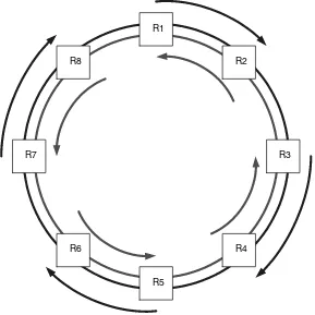
Spatial Reuse Protocol (SRP) was originally developed by Cisco in the late 1990s. It is a resilient, ring-based MAC protocol, which can use a variety of Layer 1 media but, almost invariably, is currently implemented using SONET/SDH encapsulation. This protocol has been documented in an informational RFC (RFC 2892) and adopted by the IEEE to produce Redundant Packet Ring (RPR) 802.17. Dynamic Packet Transport (DPT) is Cisco’s implementation of SRP/RPR.
MAC addresses allows hosts to identify whether there has been a wrap of the ring (see below for a further explanation).
SRP can use mechanisms associated with the Layer 1 functionality (e.g. Loss of Signal (LOS), Loss of Light (LOL) with SONET/SDH) to identify the failure of links and nodes. However, since it is not constrained to media with this functionality built in, it is necessary to include a keepalive function. In the absence of any data to send, a router will transmit keepalives to its neighbour.
As can be seen from Figure 2.2, it is possible for several pairs of nodes to communicate at full line rate, simultaneously, without any interference. However, this relies upon the communicating nodes not having to pass through other nodes and no other node needing to communicate with yet another node. For example, R1 and R2 can communicate with each other and R3 and R4 can communicate with each other. However, if R1 and R4 wanted to communicate and R2 and R3 wanted to communicate, they would have to share the bandwidth between R2 and R3.
SRP uses some Cisco-patented algorithms to ensure fairness of access to the ring. These prevent traffic on the ring from starving a particular node of capacity to insert traffic onto the ring or vice versa. A full description of the algorithms is included in RFC 2892.
R8
R5
R2
R4 R1
R3
R6 R7
2.5.1
INTELLIGENT PROTECTION SWITCHING
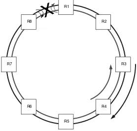
One of the features of SRP is the ability to protect against single or double fibre breaks or the total loss of a router. For two such examples, see Figures 2.3 and 2.4. In Figure 2.3 the link between R1 and R8 is broken in both directions (although, in most senses, the same processes would apply if only one of the fibres was broken). As R1 and R8 notice that they are no longer receiving traffic, each will internally wrap the failed transmit circuit back onto the receive circuit. This will create a new topology, and all nodes will be informed that there is a ring wrap. IPS failure protection and restoration are achieved in less than 50 milliseconds, which is equivalent to the restoration speeds required by SONET and SDH systems.
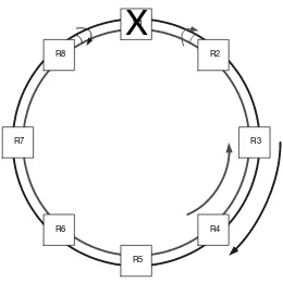
In Figure 2.4, router R1 has failed. In this case, R2 and R8 will identify the failure. Each will then wrap the transmit port normally transmitting towards R1 back to the receive port from R1. Again, the topology will change and all nodes will be informed of the fact that there is a ring wrap on the network.
A well-designed DPT or RPR network can provide exceptionally efficient connectivity over local and wide area networks. In theory, it is possible to build DPT/RPR rings spanning entire continents and including up to 255 nodes. However, this is unlikely to be the most efficient use of this media. Constraining the diameter and, more importantly,
R8
R5
R2
R4 R1
R3
R6 R7
X
R8
R5
R2
R4 R1
R3
R6 R7
X
Figure 2.4 Node lost, ring wrapped at adjacent nodes
the number of nodes on the ring will improve the efficiency of the network. In reality, no more than 64 nodes are permitted on a single ring.
2.6
(FRACTIONAL) E1/T1/E3/T3
These lower speed interfaces are commonly used between the provider edge and customer edge. Despite the significant inroads being made by Ethernet to the edge, these interfaces are still dominant because of the lack of widespread availability of Ethernet-based services beyond the urban centres.
2.7
WIRELESS TRANSPORT
This is a very broad area, which could fill an entire book of its own. However, in the limited space available, I’ll try to cover the basic issues, which any operator of a wireless network will need to address.
The term wireless covers a multitude of transmission techniques and access formats. Wireless transport mechanisms can support point-to-point, point-to-multipoint and broad-cast systems. The challenges associated with building wireless networks combine many of the same challenges associated with using any other media along with a whole list of unique problems linked with the air interface. Regulatory constraints, interference, obstructions and even atmospheric conditions all place extra burdens on the network designer. Each of these is discussed below.
2.7.1
REGULATORY CONSTRAINTS
There are a number of different regulatory environments throughout the world, each of which has slightly different rules governing the use of particular frequencies, the maximum transmission power, even the type of service, which may be offered using particular spectrum. Some bands require the payment of licence fees and are more heavily regulated while others are either unlicensed or licence exempt. Even the licence-exempt bands are subject to certain regulations.
2.7.2
INTERFERENCE
Interference refers to any signal that causes the desired signal to be indistinguishable from the surrounding noise. This can be an unwanted signal being received at a very high power level, which masks the required signal being received at a much lower power signal. Alternatively, it can be another source transmitting simultaneously on the same frequency.
2.7.3
OBSTRUCTIONS
The term wireless covers both radio and optical-based systems. Optical systems clearly require line of sight between transmitter and receiver. The line of sight has the diameter equal to the diameter of the aperture of the transmitter. Any obstruction in the path will effectively stop all transmission.