CR-Form-v3
CHANGE REQUEST
AS Topic 2 CR ?
rev
-
Current version:
OGC 08-015
For
HELP
on using this form, see bottom of this page or look at the pop-up text over the
symbols.
Proposed change affects:
AS
X
Imp Spec
Best Practices Paper
Other
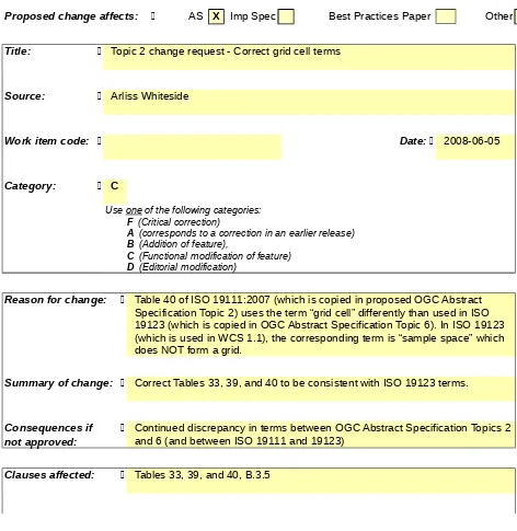
Title:
Topic 2 change request - Correct grid cell terms
Source:
Arliss Whiteside
Work item code:
Date:
2008-06-05
Category:
C
Use one of the following categories:
F (Critical correction)
A (corresponds to a correction in an earlier release)
B (Addition of feature),
C (Functional modification of feature)
D (Editorial modification)
Reason for change:
Table 40 of ISO 19111:2007 (which is copied in proposed OGC Abstract
Specification Topic 2) uses the term “grid cell” differently than used in ISO
19123 (which is copied in OGC Abstract Specification Topic 6). In ISO 19123
(which is used in WCS 1.1), the corresponding term is “sample space” which
does NOT form a grid.
Summary of change:
Correct Tables 33, 39, and 40 to be consistent with ISO 19123 terms.
Other specs
X
Other core specifications
GML 3.1 and 3.2.1, WCS 1.1, GML 3.1.1
grid CRS profile
Affected:
Abstract specifications
X
Best Practices Papers
Definition identifier URNs in OGC
namespace
Supporting Doc.
Other comments:
This change request is written as changes to ISO 19111:2007, now copied in
OGC 08-015.
Changes are also desirable in ISO 19123:2005 (OGC Topic 6), to correctly
match ISO 19111:2007.
Status
This change request, after this editing, was approved in the March 2008
meeting of the CRS DWG.
Disposition
Edit Tables
40,
39 and
40 33
of ISO 19111:2007 to read:
Table 1 — Defining elements of CD_PixelinCell class
Description: Specification of the way the image coverage grid is associated with the image data coverage range (pixel) values. As specified in ISO 19123, grid coverage range (or image pixel) values are for the grid points, which are at the corners of coverage grid cells. However, some image CRSs consider pixel cells that crudely approximate sample spaces as defined in ISO 19123, with image pixel values for the centres of these pixel cellsattributes.
Stereotype: CodeList Inheritance from: (none) Association roles: (none)
Used by: CD_ImageDatum Public attributes:
Attribute name UML identifier Data type Obligation Maximum Occurrence
Attribute description
Cell center cellCenter CharacterString C 1 The origin of the image coordinate system is the centre of a the coverage grid cell which has (at least) one corner at the anchorDefinition grid point for that image or image pixel.
Cell corner cellCorner CharacterString C 1 The origin of the image coordinate system is the
anchorDefinition grid point for that image, at the position of that image pixel (coverage range) value. (This grid point is at the corner of a coverage grid cell, as grid cell is specified in ISO 19123)or half-way between the centres of adjacent image pixels.
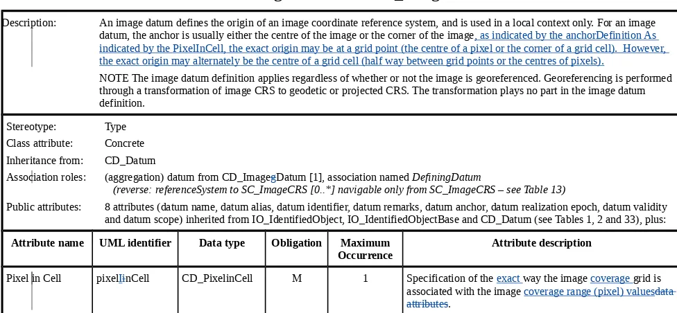
Table 2 — Defining elements of CD_ImageDatum class
Description: An image datum defines the origin of an image coordinate reference system, and is used in a local context only. For an image datum, the anchor is usually either the centre of the image or the corner of the image, as indicated by the anchorDefinition As indicated by the PixelInCell, the exact origin may be at a grid point (the centre of a pixel or the corner of a grid cell). However, the exact origin may alternately be the centre of a grid cell (half way between grid points or the centres of pixels).
NOTE The image datum definition applies regardless of whether or not the image is georeferenced. Georeferencing is performed through a transformation of image CRS to geodetic or projected CRS. The transformation plays no part in the image datum definition.
Stereotype: Type Class attribute: Concrete Inheritance from: CD_Datum
Association roles: (aggregation) datum from CD_ImagegDatum [1], association named DefiningDatum
(reverse: referenceSystem to SC_ImageCRS [0..*] navigable only from SC_ImageCRS – see Table 13)
Public attributes: 8 attributes (datum name, datum alias, datum identifier, datum remarks, datum anchor, datum realization epoch, datum validity and datum scope) inherited from IO_IdentifiedObject, IO_IdentifiedObjectBase and CD_Datum (see Tables 1, 2 and 33), plus:
Attribute name UML identifier Data type Obligation Maximum Occurrence
Attribute description
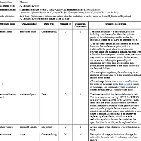
Table 3 — Defining elements of CD_Datum class
Description: A datum specifies the relationship of a coordinate system to an object, thus creating a coordinate reference system. For geodetic and vertical coordinate reference systems, the datum relates the coordinate system to the Earth. With other types of coordinate reference systems, the datum may relate the coordinate system to another physical or virtual object. A datum uses a parameter or set of parameters that determine the location of the origin of the coordinate reference system. Each datum subtype can be associated with only specific types of coordinate reference systems.
Stereotype: Type Class attribute: Abstract
Inheritance from: IO_IdentifiedObject
Association roles: (aggregation) datum from SC_SingleCRS [0..1], association named DefiningDatum
(reverse: referenceSystem to SC_SingleCRS [0..*] navigable only from SC_SingleCRS – see Table 5)
Public attributes: 4 attributes (datum name, datum alias, datum identifier and datum remarks) inherited from IO_IdentifiedObject and IO_IdentifiedObjectBase (see Tables 1 and 2), plus:
Attribute name UML identifier Data type Obligation Maximum
Occurrence Attribute description
Datum anchor anchorDefinition CharacterString O 1 The datum definition – a description, possibly including coordinates of an identified point or points, of the relationship used to anchor the coordinate system to the Earth or alternate object. - For a geodetic datum, this anchor may be a point known as the fundamental point, which is traditionally the point where the relationship between geoid and ellipsoid is defined, together with a direction from that point. In other cases, the anchor may consist of a number of points. In those cases, the parameters defining the geoid/ellipsoid relationship have then been averaged for these points, and the coordinates of the points adopted as the datum definition.
- For an engineering datum, the anchor may be an identified physical point with the orientation defined relative to the object.
- For an image datum, the anchor is usually either the centre of the image or the first-recorded corner of the image. The coordinate system orientation is defined through the CS_AxisDirection class. Datum realization
epoch
realizationEpoch Date O 1 The time after which this datum definition is valid. This time may be precise (e.g. 1997.0 for IRTF97) or merely a year [e.g. 1986 for NAD83(86)]. In the latter case, the epoch usually refers to the year in which a major recalculation of the geodetic control network, underlying the datum, was executed or initiated. An old datum may remain valid after a new datum is defined. Alternatively, a datum may be replaced by a later datum, in which case the realization epoch for the new datum defines the upper limit for the validity of the replaced datum. Datum validity domainOfValidity EX_Extent O 1 Area or region or time frame in which this datum is
valid.