Combustion in the gasoline engine The spark-ignition or
Otto-cycle engine 2
Gasoline-engine management
Technical requirements 4
Cylinder charge 5
Mixture formation 7
Gasoline-injection systems
Overview 10
K-Jetronic
System overview 13
Fuel supply 14
Fuel metering 18
Adapting to operating conditions 24 Supplementary functions 30
Exhaust-gas treatment 32
Electrical circuitry 36
Workshop testing techniques 38
K-Jetronic
Since its introduction, the K-Jetronic gasoline-injection system has pro-ved itself in millions of vehicles. This development was a direct result of the advantages which are inherent in the injection of gasoline with regard to demands for economy of operation, high output power, and last but not least improvements to the quality of the exhaust gases emitted by the vehicle. Whereas the call for higher engine output was the foremost consideration at the start of the development work on gasoline injection, today the target is to achieve higher fuel economy and lower toxic emissions.
Between the years 1973 and 1995, the highly reliable, mechanical multi-point injection system K-Jetronic was installed as Original Equipment in series-production vehicles. Today, it has been superseded by gasoline injection systems which thanks to electronics have been vastly im-proved and expanded in their func-tions. Since this point, the K-Jetronic has now become particularly impor-tant with regard to maintenance and repair.
Fuel supply
The fuel supply system comprises – Electric fuel pump,
– Fuel accumulator, – Fine filter,
– Primary-pressure regulator and – Injection valves.
An electrically driven roller-cell pump pumps the fuel from the fuel tank at a pressure of over 5 bar to a fuel accu-mulator and through a filter to the fuel distributor. From the fuel distributor the fuel flows to the injection valves. The injection valves inject the fuel con-tinuously into the intake ports of the engine. Thus the system designation K (taken from the German for continuous). When the intake valves open, the mixture is drawn into the cylinder.
The fuel primary-pressure regulator maintains the supply pressure in the system constant and reroutes the excess fuel back to the fuel tank.
Owing to continual scavenging of the fuel supply system, there is always cool fuel
available. This avoids the formation of fuel-vapor bubbles and achieves good hot starting behavior.
Electric fuel pump
The electric fuel pump is a roller-cell pump driven by a permanent-magnet electric motor.
The rotor plate which is eccentrically mounted in the pump housing is fitted with metal rollers in notches around its circumference which are pressed against the pump housing by centrifugal force and act as rolling seals. The fuel is car-ried in the cavities which form between the rollers. The pumping action takes place when the rollers, after having closed the inlet bore, force the trapped fuel in front of them until it can escape from the pump through the outlet bore (Figure 4). The fuel flows directly around the electric motor. There is no danger of explosion, however, because there is never an ignitable mixture in the pump housing.
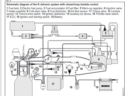
Schematic diagram of the K-Jetronic system with closed-loop lambda control
1 Fuel tank, 2 Electric fuel pump, 3 Fuel accumulator, 4 Fuel filter, 5 Warm-up regulator, 6 Injection valve, 7 Intake manifold, 8 Cold-start valve, 9 Fuel distributor, 10 Air-flow sensor, 11 Timing valve, 12 Lambda sensor, 13 Thermo-time switch, 14 Ignition distributor, 15 Auxiliary-air device, 16 Throttle-valve switch, 17 ECU, 18 Ignition and starting switch, 19 Battery.
The electric fuel pump delivers more fuel than the maximum requirement of the engine so that compression in the fuel system can be maintained under all oper-ating conditions. A check valve in the pump decouples the fuel system from the fuel tank by preventing reverse flow of fuel to the fuel tank.
The electric fuel pump starts to operate immediately when the ignition and start-ing switches are operated and remains switched on continuously after the engine has started. A safety circuit is incorpor-ated to stop the pump running and, thus, to prevent fuel being delivered if the ig-nition is switched on but the engine has stopped turning (for instance in the case of an accident).
The fuel pump is located in the imme-diate vicinity of the fuel tank and requires no maintenance.
Fuel accumulator
The fuel accumulator maintains the pressure in the fuel system for a certain time after the engine has been switched off in order to facilitate restarting, parti-cularly when the engine is hot. The spe-cial design of the accumulator housing (Figure 5) deadens the sound of the fuel pump when the engine is running.
The interior of the fuel accumulator is divided into two chambers by means of a diaphragm. One chamber serves as the accumulator for the fuel whilst the other represents the compensation volume and is connected to the atmosphere or to the fuel tank by means of a vent fitting. During operation, the accumulator chamber is filled with fuel and the dia-phragm is caused to bend back against the force of the spring until it is halted by the stops in the spring chamber. The diaphragm remains in this position, which corresponds to the maximum accumu-lator volume, as long as the engine is running.
K-Jetronic
15
Fuel accumulator a Empty, b Full.
1 Spring chamber, 2 Spring, 3 Stop, 4 Diaphragm, 5 Accumulator volume, 6 Fuel inlet or outlet, 7 Connection to the atmosphere.
Operation of roller-cell pump 1 Suction side, 2 Rotor plate, 3 Roller, 4 Roller race plate, 5 Pressure side. Electric fuel pump
1 Suction side, 2 Pressure limiter, 3 Roller-cell pump, 4 Motor armature, 5 Check valve, 6 Pressure side.