Performance of Organic Rankine Cycle in Different Refrigerants
for Low Temperature Geothermal using Delphi Program
Prabowo, Andre G.T., Ekadewi
Department of Mechanical Engineering, ITS, Surabaya E-mail: [email protected]
ABSTRACT
A software has been developed in a Windows-based Delphi programming for analyzing the influence of the transport and thermodynamic properties of the refrigerants on the performance of the Organic Rankine Cycle (ORC). Its user-friendly drag and drop icon format and excellent color graphics make it an interactive tool for teaching and the preliminary design of the ORC system. The research was carried out by analyzing the performance of the system components and the overall ORC based on the several working fluids within R22, R123, R134a and RC318. The pressure of evaporator was varied in two steps 7 and 12 bar, while the condenser was kept constant pressure at 1 bar. The turbine inlet temperature was varied in the range 100 0C to 140 0C where the various isentropic efficiency inputs were applied for pump and turbine. By
increasing turbine inlet temperature, R22 has the highest turbine work output and cycle efficiency. Contrary, RC318 has the lowest cycle efficiency and decreases trend with enhancing in turbine inlet temperature. RC318 has low latent heat of vaporization thus vaporizes under relatively very low evaporator heat supply.
Keywords: Organic rankine cycle, delphi program, performance analysis.
INTRODUCTION
Geothermal heat sources vary in temperature from 50 to 300 0C, and can be superheated, mainly
saturated steam or just a mixture of steam and water. Generally, the high temperature (>170 0C)
and pressure (> 6 bar) are suitable for commercial production of electricity. In reality, however, only small number of geothermal wells can produce high temperature steam. In Mataloko-NTT east part of Indonesia, almost 50% of geothermal wells were producing steam in low temperature (< 150 0C) and
became un-useful.
Organic Rankine Cycle (ORC) with refrigerant as working fluid are the most common technology for utilizing such low temperature resources for producing of electricity [1-3]. Like the Rankine cycle, the main components of this system consists of the evaporator, condenser, pump and turbine. This system requires only low temperature and pressure heat sourcesto produce vapor that turns the turbine to generate electricity and this system also does not require a furnace as the heating component which has pollution effects to the environment.
A regenerative cycle improves the efficiency of an ORC and reduces irreversibility when Pedro et all [4] use various classes of organic working fluid. The cycle power will increase by increasing the mass flow rate of geothermal steam entering the evaporator by mixing the steam from the source with a portion of
recirculated steam from the evaporator exit [5]. The effect of various working fluid on the thermal efficiency ORC has been investigated [6]. It is found that the presence of hydrogen bond in certain molecules such as water, ammonia and ethanol may result in lager vaporizing enthalpy, and is regarded as inappropriate for ORC system. Experimental study was also proposed to improve the thermal efficiency by using solar energy [7]. A displacement-type scroll expander and compound parabolic concentrator solar collector are used.
In this study, a user-friendly computer software was developed for analyzing the influence of the transport and thermodynamic properties of the refrigerants as working fluid on the ORC perfor-mance. The overall performance of the system in producing power; including the efficiency and turbine power output of the various refrigerants with change in enthalpy will also be discussed.
RESEARCH METHODOLOGY
Analysis of an ORC System
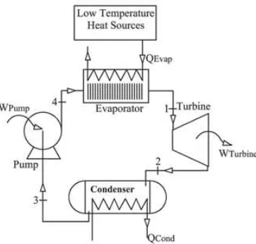
Figure 1. Schematic of the ORC System
In the same time, the thermal energy of the vapor is converted to mechanical power and will produce electricity if generator is connected to turbine shaft. The vapor leaving the turbine is then condensed at the condenser and pumped back to the evaporator. The working fluid then passes through a series of devices in a closed cycle.
By modeling each device, a complete cycle simulation is achieved. The simulation requires such condition as the turbine inlet pressure P1 is changed
in two steps 7 and 12 bars, besides that the turbine outlet pressure P2 was kept constant at 1 bar. The
turbine inlet temperature is set between 100 to 140
0C to be a superheated phase. The working fluid
passing through the condenser is assumed to be a saturated liquid. The isentropic efficiencies of the turbine and pump are assumed to be 80%. In this simulation, each stage of the working fluid is expressed by the equation (1) to (6) [8]. The equations are used to determine the cycle efficiencies for basic ORC configurations are presented in this section. The thermodynamic model presented in this chapter assumes the following: 1) steady state conditions and 2) no pressure drop in the evaporator, condenser, and pipes.
)
(
1 22
1
h
Th
h
sh
−
=
η
−
Process 1-2 (Turbine)
The superheated vapor of the working fluid passes through the turbine to generate mechanical power. The vapor expands in the casing and it will drive the turbine blades. The vapor comes out of the turbine at lower pressure P2. The turbine power is
given by:
Where
η
Tis the isentropic efficiency of the turbine,m
is the working fluid mass flow rate, h1 is the specific enthalpy of the working fluid at the inlet turbine, h2sand h2are the specific enthalpies outlet of the turbine for isentropic and actual process, respectively.Process 2-3 (Condenser)
In the condenser, the superheated vapor of the working fluid goes through desuperheating and phase change (condensation) process at constant pressure into a state of saturated liquid. The con-denser heat rejection rate is expressed as,
(3)
The working fluid (saturated liquid) is leaving the condenser at low pressure P3 and brought to high
pressure P4 by the pump. The working fluid is
pumped back into the evaporator. The pump power can be expressed as,
(4)
Where
η
P is the isentropic efficiency of the pump, h3 is the specific enthalpy of the working fluid at the inlet pump, h4sand h4 are the specific enthalpies of the working fluid at the outlet of the pump for the ideal and actual case, respectively.4
Process 4-1 (Evaporator)
In the evaporator, the low temperature geother-mal heats the working fluid from the pump outlet to the turbine inlet condition. Taking a control volume enclosing the evaporator, the heat transfer rate from the energy source into the working fluid is given by,
(5)
The cycle efficiency is defined as the ratio between the net power of the cycle to the evaporator heat rate. It gives a measure about how much of the waste heat input to the working fluid passing through the evaporator is converted to the net work output and can be expressed as,
Organic Working Fluids
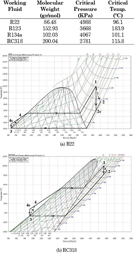
Tabel 1. Thermal Properties of Working Fluids
Working Fluid
Molecular Weight (gr/mol)
Critical Pressure
(KPa)
Critical Temp.
(°C)
R22 86.48 4988 96.1
R123 152.93 3668 183.9
R134a 102.03 4067 101.1
RC318 200.04 2781 115.8
(a) R22
(b) RC318
Figure 2. T-s Diagram for Working Fluid Considered
There are several criteria for the organic substance that was selected as the working fluid. Such as non ozone depletion, non toxicity, non corrosiveness and non flammability are a few physical and chemical characteristics [2]. Besides that, the working fluid should have relatively low boiling point to be used in a organic Rankine cycle, since low temperature geothermal was used as heat source. In a ORC design, however, not all the general requirements can be satisfied. Table 1 lists the thermal properties of these working fluids. R22 has the smallest molecular weight, this mean R22 has density smaller than the others. Contrary, RC318 has the biggest molecular weight, this mean using the same pump capacity, RC318 has the highest mass flow rate.
Figure 2a and b present T-s diagram for R22 and RC318, respectively [9]. The different of entropy
between saturated gas and saturated liquid (sfg)
represents big or small latent heat. In addition, a highest latent heat means the largest portion of the energy supplied is taken up during phase change at constant temperature and pressure. The working fluid, R22, has wider T-s than the other organic fluids, this is taking up more heat during evaporation. Contrary, RC318 has narrower T-s diagram, thus less heat during evaporation. The state condition of RC318 has always superheated vapor out from turbine even inlet turbine in saturated vapor condition.
Description of Software
A window-based Delphi programming have been created to determine the influences of the transport and thermodynamics properties including specific volume, viscosity, thermal conductivity, latent heat and enthalpy for different refrigerant in performance trend of ORC. Thermodynamics pro-perties of common refrigerant where have been extracted from NIST [10], and then the database was built in the Delphi program using Microsoft Access format. The existing databases of refrigerant properties cater for R22, R123, R134a and RC318. These kinds of properties are automatically calculated based on input fluid temperatures and pressure in every stage.
Figure 3. The Beginning Form
Figure 5. Input Format for Temperature, Pressure and Kind of Working Fluid
In simulation process, the software will display each components of the ORC system (turbine, reheat turbine, condenser, pump and evaporator) as shown in Figure 3 for the beginning form. Then, the user can drag the select components/icons and drop to the empty form. Connecting each component to make organic Rankine cycle system as shown in Figure 4. Some buttons such as connected, auto connected, delete line, delete component, clear screen have been prepared to operate this simulator easier for the preliminary design ORC system. Besides that, excellent color graphics features and attractive icon make it an interactive tool for teaching of ORC cycle. After finishing the design of ORC system, pressure and temperature will be inputted for each compo-nent like evaporator, turbine, condenser and pump as described in Figure 5. The SI units option pressure (bar or MPa) and temperature (0C or K) are
built into the software. The various isentropic efficiencies for pump and turbine are included in the software. The user also can choose the kind of working fluid will be used.
RESULT AND DISCUSSION
Numerical Simulation Results
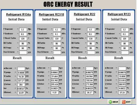
Based on data inputted by the user viz. temperature, pressure, isentropic efficiency and kind of working fluids, the software will automatically calculate the turbine work (WT), pump work (WP), heat input evaporator (Qevaporator), heat rejection condenser (Qcondenser) all units in KJ/kg, cycle efficiency (η%) and back work ratio (bwr) as described in Fig. 6. In the others form of the result, the simulator will displayed T-s diagram, thermo-dynamic properties and state of condition for working fluid in each stage as shown in Figure 7.
To see the effect of working fluids on the thermal performance ORC cycle under same temperature and pressure on each stage, the user must return to the input format data and change the
working fluid to other refrigerant. With the same procedure, the simulator will display the comparison of thermal performance for ORC in different working fluids as shown in Figure 8.
Figure 6. Calculation Results
Figure 7. T-s Diagram and Model Process
Figure 9a and 9b show the dependence of the turbine work (KJ/kg) on the different turbine inlet temperature under superheated vapor condition for pressure 7 bar and 12 bar respectively, with constant pressure 1 bar at condenser. In the case of R22 and R134a at pressure 7 bar, the work turbine significantly increases with increase in the turbine inlet temperature. The work turbine is calculated by Equation (2) with the isentropic efficiency of the turbine is assumed to be 80%. As this equation, increasing the value of enthalpy inlet turbine will formulate the turbine work output become enlarge. For R123 and RC318, it only slightly increases and also the value of the turbine work output is small. The relationship the work turbine and the temperature inlet turbine is expressed as a straight line. For the evaporator pressure 12 bar, the turbine work has same tendency with Figure 9a only the value relatively higher than pressure 7 bar.
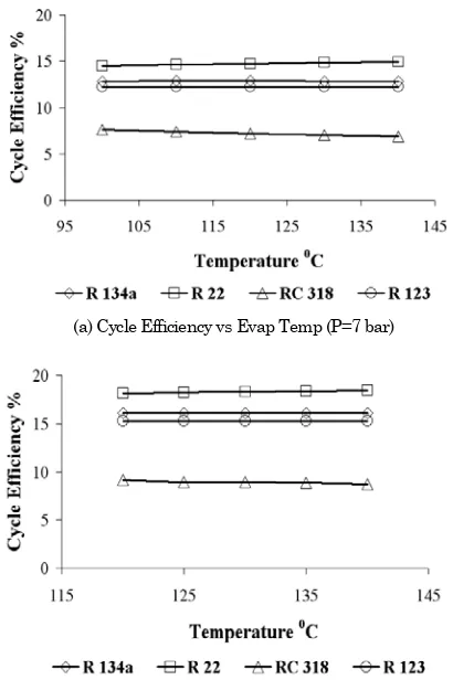
Figure 10a and b present the effect of the turbine inlet temperature on the cycle efficiency under superheated vapor condition for pressure 7 bar and 12 bar respectively, with constant pressure 1 bar at condenser.
(a) Turbine Work vs Evap Temp (P=7 bar)
b) Turbine Work vs Evap Temp (P=12 bar)
Figure 9. The Effects of the Turbine Inlet Tempera-ture on Turbine Work
(a) Cycle Efficiency vs Evap Temp (P=7 bar)
(b) Cycle Efficiency vs Evap Temp (P=12 bar)
Figure 10. The Effects of the Turbine Inlet Tempera-ture on Cycle Efficiency
R22 has the highest cycle efficiency and increases trend with enhancing in the turbine inlet temperature. Therefore raising the temperature inlet turbine and pressure, give us much higher system performance. Inline with R22, R123 and R134a have also increase trend. Conversely, RC318 has lowest the cycle efficiency and decreases tendency for increasing turbine inlet temperature. Thus RC318 will give the best efficiency if it is operated at saturated vapor condition. For the pressure 12 bar Figure 10b, the cycle efficiency has same gradient with Fig. 10a only the value slightly higher than pressure 7 bar. These results, however, tell us the characteristics of each working fluid and the effect of the temperature inlet turbine.
Component Transport Properties Analysis
The working fluid, RC318, has the lowest specific volume and the value will enlarge in higher pressure P=12 bar. Because the vapor will expands in casing turbine to generate mechanical power, increasing the specific volume indicates an increase the turbine work.
Figure 12 shows the impact of evaporator pressure on the enthalpy of vaporization (hfg). Almost
all working fluids have same trend with decreasing latent heat of vaporization as the evaporator pressure increase. RC318 has the lowest enthalpy of vaporization thus vaporizes under relatively very low evaporator heat supply.
(a) Spesific Volume vs Evaporatoe Temperature (P=7 bar)
(b) Spesific Volume vs Evaporatoe Temperature (P=12 bar)
Figure 11. The Effects of the Turbine Inlet Tempera-ture on Specific Volume of the Working Fluid
Figure 12. The Impact of the Evaporator Pressure on Enthalpy of Vaporization
CONCLUSION
A software developed using Delphi Program can be used for simulation and analysis of the effect of thermodynamic and transport properties of some working fluids, i.e. R22 (Chlorodifluoromethane), R123 (Dichlorotrifluoroethane), R134a (Tetrafluoro-ethane), and RC318 (Octafluorocyclobutane) on an Organic Rankine Cycle (ORC).
From the simulation, it was found that R22 gives the highest turbine work output and cycle efficiency, while RC318 gives the lowest. Increasing the turbine inlet temperature, the cycle efficiency using R22 tends to increase while RC318 tends to decrease. RC318 has the lowest latent heat of vaporization thus vaporizes under relatively very low evaporator heat supply.
REFERENCES
1. Yamamoto T, Furuhata T, Arai N, Mori K,
"Design and Testing Of The Organic Rankine Cycle", Energy Journal, vol. .26, pp. 239-251, 2001.
2. Madhawa HD, Mihajlo G, William MW, Ikegami Y, "Optimum Design Criteria for an Organic Rankine Cycle Using Low-Temperature Geother-mal Heat Sources", Energy Journal, vol. 32, pp 1698-1706, 2007.
3. Donghong W, Xuesheng L, Zhen L, Jianming G,
"Performance Analysis And Optimization Of Organic Rankine Cycle (ORC) For Waste Heat Recovery", Energy Conversion and Management Journal, vol. 48, pp. 1113-1119, 2007.
4. Pedro JM, Louay MC, Kalyan S, Chandramohan
S, "An Examination of Regenerative Organic
Rankine Cycle Using Dry Fluid", Applied
Thermal Engineering Journal, vol. 28, pp. 998-1007, 2008.
5. Aleksandra BG, Wladyslaw N, "Maximising The Working Fluid Flow As A Way Of Increasing
Power Output Of Geothermal Power Plant",
Applied Thermal Engineering Journal, vol. 27, pp. 2074-2078, 2007.
6. Bo-Tau Liu, Kuo-Hasiang C, Chi-Chuan W.,
"Effect of Working Fluids on Organic Rankine Cycle for Waste Heat Recovery", Journal Energy, vol. 29, no.4, pp. 1207-1217, 2004.
7. Saitoh T, Yamada N, Wakashima S, "Solar Rankine Cycle System Using Scroll Expander", Journal of Environment and Engineering, vol. 2, no. 4, pp. 708-719, 2007.
9. Arne J., Bjarne D.R., Morten J.S., Simon E.A., CoolPack ver 1.46, Dept. of Energy Eng., Technical University of Denmark (DTU), May 2001.