Distance Estimation of Colored Objects in Image
Arif Rahman
1, a)Nuryono Satya Widodo
2, b)1Information System Department, 2 Electrical Engineering Department
Ahmad Dahlan University
Jl. Prof. Dr. Soepomo, SH, Janturan Yogyakarta, Indonesia.
a)Corresponding author: [email protected] b) [email protected]
Abstract. Detect objects with a specific color are one of the topics in computer vision. An object captured by the camera will be represented as an image. Closer objects will appear larger in the image and vice versa. However, size changes of the object do not inform actual distance of the object to the camera. This paper proposes a method to estimate the distance between the colored object to the camera by processing the image captured. First, image color filtering based on HSV color model performed and then to detect the colored object in the image, object detection applied to labeling nearest 8 connected components with the same value with Moore-neighborhood tracing algorithm. The distance of the object estimates with single point projection principle from the object height in the image represented by the bounding rectangle, and the height of the real object. An experiment conducted using objects with different color and object distance variance in centimeters. Results show that the method is able to estimate the real distance of the colored object from the camera.
INTRODUCTION
Object detection can be done with various methods, through feature detection [1] or by its color [2]. The color feature is invariant with respect to scaling, translation, and rotation of an image. The color in the digital system can be represented in a variety of color models. Image processing hardware, in general, applies the RGB color model with the consideration of the ease in technical color displaying. Other color model focuses on human’s eye perception to the color, such as HSL. This color model represents color as three components, Hue (H), Saturation (S) and Value (V). Hue is an attribute of human perception and can be described as red, green, blue, purple, and yellow as primary hues or any intermediate combinations of them. The colorfulness of a color is described by the saturation component, a measure of colorfulness or whiteness in the color perceived. The Value gives a measure of the brightness of colors, a measure of how much light is reflected from the object or how much light is emitted from a region.
A real object captured by the digital camera will be represented as a digital image. Closer objects will appear larger in the image and vice versa. The Object size in an image does not explicitly informs the actual distance of the object to the camera[3]. This paper proposes a method to estimate the distance between the colored object to the camera by processing the image captured.
METHODS
FIGURE 1. Sequential processes to estimates distance of an object in image
Image Acquisition
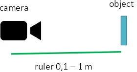
In this research, a digital image from real objects captured using a simple generic web camera without a zoom feature. The reason for this is because this research developed for the system with limited computing resource and camera such as a robot or a mobile system. Fixed image resolution is used in this process to simplify the calculation of object height in the image which is using the ratio between the image height and real object’s height. In this paper, resolution 640x480 pixels for an image is used. Image acquisition is done at a distance in the range of one meter with markers with length difference 10 centimeters each. Object position is aligned with the camera lens. The position of the camera shifts along the ruler. Image acquisition process to estimate the distance of the real object is shown in Figure 2
FIGURE 2. Image acquisition process
Image Color Filtering
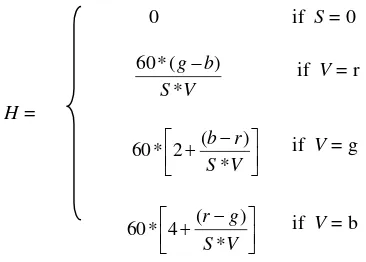
Image that has been captured by the camera has the RGB color model, however color filtering process in this paper is using HSV color model which is focussing on human’s eye preception of the colors. So, color conversion is needed in order to filter color of pixel in image appropriately. Color conversion from RGB to HSV steps are as follows [4] : r, g, b values are first obtained by normalizing each color of pixel such that:
(4)
In HSL Color filtering, pixels with color in the specified range of H, S, and V value will pass the filter, and therefore marked with 1 in binary image which is the output of this filter. Otherwise, pixels will be marked as 0 in output. HSV filtering can be expressed as Equation (6)
(6)
𝐹𝐻𝑆𝑉(𝑝𝑖) = { 1, 𝑚𝑖𝑛0, 𝐻≤ 𝐻(𝑝𝑖) ≤ 𝑚𝑎𝑥𝐻 , 𝑚𝑖𝑛𝑆≤ 𝑆(𝑝𝑖) ≤ 𝑚𝑎𝑥𝑆 ,𝑚𝑖𝑛𝐿≤ 𝑉(𝑝𝑖) ≤ 𝑚𝑎𝑥𝑉
If HSV value of pixel pi is between minimum values for each HSV component minH, minS,minV and maximum
values maxH , maxS , maxV , value of pi is 1 or white , otherwise pi is set to value 0 or black.
Object Detection
Binary image from the color filtering process, then analyzed to detect the object. Image contour is used to represent the object. Contours in the image is detected with Moore-Neighborhood Tracing algorithm. The Moore neighborhood of a pixel is the set of 8 pixels which share a vertex or edge with that pixel as shown in Figure 3. P1, P2, P3, P4, P5, P6, P7 and P8 are the Moore neighborhood of P [5].
P1 P2 P3
P8 P P4
P7 P6 P5
FIGURE 3. The Moore neighborhood
Algorithm to detect contour in the binary image I with black background color and white pixels can be described as follow:
ALGORITHM Moore-Neighborhood Tracing
2. From bottom to top and left to right scan the cells of I until a pixel s of P is found (until the current pixel p=s is a white pixel of P), insert s in B. Let b denote the current boundary point, i.e.,
b=s.
3. Backtrack (move the current pixel to the pixel from which s was entered) and advance the current pixel p being examined to the next clockwise pixel in M(b).
while p is not equal to s do
if p is white, insert p in B, set b=p and backtrack (move the current pixel to the pixel from which p=b
was entered); else advance the current pixel p to the next clockwise pixel in M(b). end while
End
Distance Estimation
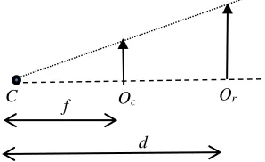
Real object distance from the camera is calculated based on the ratio of the height of detected object in an image and the real object height. Single point projection principle is used to model the relation of camera, object in image and real object as shown in Figure 4
FIGURE 4. Single point projection of object in camera
focal length f can be calculate with respect to object height in camera Oc , real object Or and the object distance d
from camera C in Equation 7. [6]
𝑓
𝑑
=
𝑂𝑐
𝑂𝑟 (7)
real object and distance are in centimeters, and height of the object in the image is expressed as a ratio between the height of the object in the image and image height in pixels.
RESULTS
The experiment was conducted on images of a squared object with red and blue color and white background color. First, images are processed to obtain the focal length of the camera, and then focal length is used to estimate the object distance from the camera. Figure 5 shows the output image of each process in this proposed method
d
(a) (b)
(c) (d)
FIGURE 5. Image output from each process (a) original image (b) color filtering, (c) detected object, (d) distance estimation
In Figure 5.(b) shows the result of color filtering with red color. The white pixels represent pixels that pass the filter in Equation 6 for HSV value of red color. Object detection is performed using bounding rectangle of white pixels as shown in (c). After object is detected, then distance calculated with the height of bounding rectangle as object height and the resukt diplayed in the image as shown in (d). Distance estimation of the red and blue objects with real object distance in interval of 10 -100 cm described in Table 1, distance and estimation are in centimeters.
TABLE 1. Distance estimation results of red and blue object
distance (d)
estimation (e)
red object blue object
10 7.918 13.624 20 16.660 16.280 30 26.900 30.867 40 51.593 33.706 50 61.514 46.135 60 66.640 53.370 70 72.699 64.211 80 79.968 68.492 90 88.854 76.102 100 106.625 91.322
To determine the difference between the real value and predicted value Root Mean Square Error (RMSE) as in Equation 8 is used. It represents the gap of real object distance from a camera and the estimated distance based on an image captured. Normalized RMSE (NRMSE) is used to represent the magnitude the error with respect to the range of value as described in Equation 9. It is shown in Table 1 that experiments result NRMSE 0.069 for red object and 0.089 for the blue object and in average is 0.079
𝑅𝑀𝑆𝐸 = √∑𝑛𝑖=1(𝑒𝑖−𝑑𝑖)2
𝑛 (8)
𝑁𝑅𝑀𝑆𝐸 =𝑑 𝑅𝑀𝑆𝐸
𝑚𝑎𝑥−𝑑𝑚𝑖𝑛 (9)
CONCLUSION
Proposed method with four sequence processes: image acquisition, color filtering, object detection and object distance estimation with single point projection principle is able to predict the distance between the object and the simple generic webcam. The experiment result shows that the distance estimation of two objects with different color has average normalized error NMRSE 0.079 for the distance range 10 to 100 centimeters which mean the distance prediction has error 7.9%
The accuracy of object detection by its color needs to be improved, especially in color filtering process due to illumination of the object. The method proposed also could be implemented to the video to get real-time distance prediction of the object.
REFERENCES
1. Long F., Zhang H., Feng D., Fundamentals of Content-based Image retrieval, Multimedia Information Retrieval and Management - Technological Fundamentals and Applications, D. Feng, W.C. Siu, and H.J.Zhang. (ed.), Springer (2002)
2. Gevers, Theo, Smeulders, Arnold WM, Color-based Object Recognition, Pattern Recognition,32,3, Pergamon, (1999) pp. 453-464
3. Rahman, Ashfaqur, et al. An image based approach to compute object distance. International Journal of Computational Intelligence Systems 1.4 (2008) pp. 304-312.
4. Acharya T., Ray A.K., Image Processing Principles and Applications, by John Wiley & Sons, (2005) 5. Pradhan, Ratika, et al. Contour line tracing algorithm for digital topographic maps. International Journal of
Image Processing (IJIP) 4.2 (2010): 156-163.