Series Editor: David Hutchison,Lancaster University, Lancaster, UK Series Advisers: Serge Fdida,Universite´ Pierre et Marie Curie, Paris, France
Joe Sventek,University of Glasgow, Glasgow, UK
The ‘Wiley Series in Communications Networking & Distributed Systems’ is a series of expert-level, technically detailed books covering cutting-edge research, and brand new developments as well as tutorial-style treatments in networking, middleware and software technologies for communications and distributed systems. The books will provide timely and reliable information about the state-of-the-art to researchers, advanced students and development engineers in the Telecommunications and the Computing sectors.
Other titles in the series:
Wright:Voice over Packet Networks0-471-49516-6 (February 2001) Jepsen:Java for Telecommunications0-471-49826-2 (July 2001) Sutton: Secure Communications0-471-49904-8 (December 2001)
Stajano:Security for Ubiquitous Computing0-470-84493-0 (February 2002) Martin-Flatin:Web-Based Management of IP Networks and Systems, 0-471-48702-3 (September 2002)
Berman, Fox, Hey:Grid Computing. Making the Global Infrastructure a Reality, 0-470-85319-0 (March 2003)
Turner, Magill, Marples: Service Provision. Technologies for Next Generation Communications0-470-85066-3 (April 2004)
Welzl:Network Congestion Control: Managing Internet Traffic0-470-02528-X (July 2005) Raz, Juhola, Serrat-Fernandez, Galis:Fast and Efficient Context-Aware Services
0-470-01668-X (April 2006)
SERVICE AUTOMATION
AND DYNAMIC
PROVISIONING
TECHNIQUES IN IP/MPLS
ENVIRONMENTS
Christian Jacquenet, Gilles Bourdon and Mohamed Boucadair
All atTelephone (þ44) 1243 779777
Email (for orders and customer service enquiries): [email protected] Visit our Home Page on www.wiley.com
All Rights Reserved. No part of this publication may be reproduced, stored in a retrieval system or transmitted
in any form or by any means, electronic, mechanical, photocopying, recording, scanning or otherwise, except under the terms of the Copyright, Designs and Patents Act 1988 or under the terms of a licence issued by the Copyright
Licensing Agency Ltd, 90 Tottenham Court Road, London W1T 4LP, UK, without the permission in writing
of the Publisher. Requests to the Publisher should be addressed to the Permissions Department, John Wiley & Sons Ltd, The Atrium, Southern Gate, Chichester, West Sussex PO19 8SQ, England, or emailed to [email protected], or faxed to (þ44) 1243 770620.
Designations used by companies to distinguish their products are often claimed as trademarks. All brand names and product names used in this book are trade names, service marks, trademarks or registered trademarks of their respective owners. The Publisher is not associated with any product or vendor mentioned in this book. All trademarks referred to in the text of this publication are the property of their respective owners.
This publication is designed to provide accurate and authoritative information in regard to the subject matter covered. It is sold on the understanding that the Publisher is not engaged in rendering professional services. If professional advice or other expert assistance is required, the services of a competent professional should be sought.
Other Wiley Editorial Offices
John Wiley & Sons Inc., 111 River Street, Hoboken, NJ 07030, USA Jossey-Bass, 989 Market Street, San Francisco, CA 94103-1741, USA Wiley-VCH Verlag GmbH, Boschstr. 12, D-69469 Weinheim, Germany
John Wiley & Sons Australia Ltd, 42 McDougall Street, Milton, Queensland 4064, Australia
John Wiley & Sons (Asia) Pte Ltd, 2 Clementi Loop #02-01, Jin Xing Distripark, Singapore 129809 John Wiley & Sons Canada Ltd, 6045 Freemont Blvd, Mississauga, ONT, L5R 4J3, Canada
Wiley also publishes its books in a variety of electronic formats. Some content that appears in print may not be available in electronic books.
Library of Congress Cataloging-in-Publication Data
Jacquenet, Christian.
Service automation and dynamic provisioning techniques in IP/MPLS environments / Christian Jacquenet, Gilles Bourdon and Mohamed Boucadair.
p. cm. Includes index.
ISBN 978-0-470-01829-3 (cloth : alk. paper)
1. MPLS standard. 2. TCP/IP (Computer network protocol) I. Bourdon, Gilles. II. BoucadaIr, Mohamed. III. Title.
TK5105.573.J33 2008 004.6’2–dc22
2007043741
British Library Cataloguing in Publication Data
A catalogue record for this book is available from the British Library
ISBN 978-0-470-01829-3 (HB)
Typeset in 10/12 pt Times by Thomson Digital, India.
Preface xi
Acknowledgements xiii
PART I ARCHITECTURES AND PROTOCOLS FOR SERVICE
AUTOMATION 1
1 Introduction 3
1.1 To Begin With 3
1.1.1 On IP Networks in General, and Routers in Particular 3 1.1.2 On the Usefulness of Dynamic Routing Protocols
in IP Networks 5
1.1.3 On the Inability of an IGP to Address Interdomain
Communication Needs 7
1.1.4 On the BGP-4 Protocol 9
1.1.5 The Rise of MPLS 10
1.2 Context and Motivation of this Book 13
1.2.1 Classifying Capabilities 14
1.2.2 Services and Policies 14
1.2.3 The Need for Automation 15
1.3 How this Book is Organized 16
1.4 What Is and What Should Never Be 16
References 16
2 Basic Concepts 19
2.1 What is a Policy? 19
2.2 Deriving Policies into Rules and Configuration Tasks 19
2.2.1 Instantiation 20
2.2.2 Device Identification 20
2.2.3 Translation 21
2.3 Storing Policies 21
2.4 Policy and Device Configuration 21
2.5 Policy-based Management Model 22
2.5.1 Reaching a Policy Decision 24
2.5.2 Requirements for a PEP–PDP Communication Protocol 24
3 The RADIUS Protocol and its Extensions 27
3.1 Protocol Design 27
3.1.1 Protocol Structure and Messages 28
3.1.2 Forces and Weaknessess 36
3.1.3 Authorization and Provisioning with RADIUS 39
3.2 Radius Extensions 44
3.2.1 EAP Support with RADIUS 44
3.2.2 Interim Accounting 47
3.2.3 Dynamic Authorization 49
3.2.4 Using RADIUS for Assignment, Prioritization and Filtering
with VLANs 51
3.2.5 Filtering IP Traffic 52
3.2.6 Future Extensions 53
3.2.7 RADIUS and its Future 55
References 59
4 The Diameter Protocol 61
4.1 Learning from RADIUS Deficiencies 61
4.1.1 General Requirements 62
4.1.2 Authentication Requirements 63
4.1.3 Authorization Requirements 64
4.1.4 Accounting Requirements 64
4.1.5 Diameter is Born 64
4.2 Diameter: Main Characteristics 65
4.2.1 Diameter Network Entities 66
4.2.2 Diameter Applications 67
4.2.3 Sessions and Connections 67
4.2.4 Diameter Routing 68
4.2.5 Peer Discovery 70
4.2.6 Peer Connection Maintenance for Reliable
Transmissions 71
4.3 Protocol Details 71
4.3.1 Diameter Header 71
4.3.2 AVP Format 73
4.3.3 Command Codes 74
4.3.4 Accounting 76
4.4 Diameter Network Access Application (NASREQ) 76
4.4.1 AVP Usage for NASREQ 77
4.4.2 Enhanced Authorization Parameters 78
4.4.3 Enhanced Authorization Examples 80
4.5 Diameter Credit Control Application 81
4.6 Diameter in NGN/IMS Architecture for QoS Control 82
4.6.1 What is an NGN? 82
4.6.2 QoS Control in ETSI/TISPAN Architecture 85
5 The Common Open Policy Service (COPS) Protocol 91 5.1 A New Scheme for Policy-based Admission Control 91
5.2 A Client–Server Architecture 92
5.3 The COPS Protocol 94
5.3.1 The COPS Header 94
5.3.2 The COPS Message Objects 95
5.4 COPS Messages 97
5.4.1 Client-Open (OPN) 97
5.4.2 Client-Accept (CAT) 97
5.4.3 Request (REQ) 97
5.4.4 Decision (DEC) 98
5.4.5 Other COPS Messages 99
5.5 Summary of COPS Operations 100
5.6 Use of COPS in Outsourcing Mode 101
5.7 Use of COPS in Provisioning Mode 101
5.7.1 On the Impact of Provisioning Mode on COPS Operations 102 5.7.2 On the Impact of Provisioning Mode on PEP–PDP Exchanges 103
5.8 Security of COPS Messages 104
References 104
6 The NETCONF Protocol 105
6.1 NETCONF at a Glance 105
6.1.1 Introduction 105
6.1.2 Motivations for Introducing NETCONF 106
6.1.3 NETCONF, an IETF Initiative 107
6.1.4 Missions of the IETF NETCONF Working Group 107
6.1.5 NETCONF-related Literature 108
6.1.6 What is In? What is Out? 109
6.2 NETCONF Protocol Overview 109
6.2.1 Some Words about XML 110
6.2.2 NETCONF Terminology 114
6.2.3 NETCONF Layer Model 114
6.2.4 NETCONF Communication Phases 116
6.2.5 NETCONF Data 117
6.2.6 NETCONF Capability Exchange 118
6.2.7 RPC Layer 120
6.2.8 NETCONF Filtering 129
6.3 NETCONF Protocol Operations 130
6.3.1 Retrieve Configuration Data 135
6.3.2 Get 137
6.3.3 Delete Configuration Data 137
6.3.4 Copy Configuration 138
6.3.5 Edit Configuration Data 139
6.3.6 Close a NETCONF Session 142
6.3.8 Lock NETCONF Sessions 144
6.3.9 Unlock NETCONF Sessions 145
6.3.10 Validate Configuration Data 146
6.3.11 Commit Configuration Changes 148
6.3.12 Discard Changes of Configuration Data 149
6.3.13 NETCONF Notification Procedure 149
6.4 NETCONF Transport Protocol 153
6.4.1 NETCONF as Transport-independent Protocol 153
6.4.2 Transport Protocol Alternatives 153
6.5 NETCONF Capabilities 162
6.5.1 URL Capability 163
6.5.2 XPath Capability 165
6.5.3 Writable-Running Capability 166
6.5.4 Candidate Configuration Capability 167
6.5.5 Confirmed Commit Capability 167
6.5.6 Validate Capability 168
6.5.7 Distinct Startup Capability 169
6.5.8 Rollback on Error Capability 170
6.5.9 Notification Capability 171
6.6 Configuring a Network Device 171
6.7 NETCONF Content Layer 173
References 173
7 Control and Provisioning of Wireless Access Points (CAPWAP) 175 7.1 CAPWAP to Address Access Point Provisioning Challenges 176
7.2 CAPWAP Concepts and Terminology 176
7.3 Objectives: What do we Expect from CAPWAP? 180
7.4 CAPWAP Candidate Protocols 182
7.5 The CAPWAP Protocol 183
7.6 CAPWAP Future 186
References 186
PART II APPLICATION EXAMPLES OF SERVICE AUTOMATION
AND DYNAMIC RESOURCE PROVISIONING TECHNIQUES 187
8 Dynamic Enforcement of QoS Policies 189
8.1 Introduction 189
8.1.1 What is Quality of Service, Anyway? 189
8.1.2 The Need for Service Level Specifications 192
8.2 An Example 193
8.3 Enforcing QoS Policies in Heterogeneous Environments 193
8.3.1 SLS-inferred QoS Policy Enforcement Schemes 193
8.3.2 Policy Rules for Configuring DiffServ Elements 197
9 Dynamic Enforcement of IP Traffic Engineering Policies 199
9.1 Introduction 199
9.2 Terminology Considerations 200
9.3 Reference Model 201
9.4 COPS Message Content 202
9.4.1 Request Messages (REQ) 202
9.4.2 Decision Messages (DEC) 203
9.4.3 Report Messages (RPT) 203
9.5 COPS-PR Usage of the IP TE Client-Type 204
9.6 Scalability Considerations 205
9.6.1 A Tentative Metric Taxonomy 205
9.6.2 Reporting the Enforcement of IP Traffic Engineering Policy 206
9.7 IP TE PIB Overview 206
9.8 COPS Usage for IP TE Accounting Purposes 207
References 208
10 Automated Production of BGP/MPLS-based VPN Networks 211
10.1 Introduction 211
10.2 Approach 212
10.3 Use of Policies to Define Rules 214
10.4 Instantiation of IP VPN Information Model Classes 214 10.5 Policy Components of an IP VPN Information Model 215 10.5.1 Physical Components of an IP VPN Information Model 216 10.5.2 Virtual Components of an IP VPN Information Model 217
10.5.3 Inheritance Hierarchy 218
10.6 Dynamic Production of IP VPN Services 221
10.7 Context of a Multidomain Environment 222
10.7.1 A Bit of Terminology 222
10.7.2 Reference Model 223
10.8 Possible Extensions of the VPN Model 224
References 224
11 Dynamic Enforcement of Security Policies in IP/MPLS Environments 227 11.1 Enforcing Security Policies for Web-based Access Control 227 11.2 Enforcing Security Policies in Companies with 802.1X 235
References 238
12 Future Challenges 239
12.1 Introduction 239
12.1.1 Current Issues with Configuration Procedures 239
12.1.2 Towards Service-driven Configuration Policies 240
12.2 Towards the Standardization of Dynamic Service Subscription
and Negotiation Techniques 241
12.2.1 Basic Motivation 241
12.2.2 Commercial Framework 241
12.2.4 Publishing and Accessing Services 243 12.2.5 Example of Automated IP VPN Service Composition 244
12.3 Introducing Self-organizing Networks 246
12.3.1 What is a Self-organizing Network? 246
12.3.2 Characteristics of SON Networks and Devices 247
12.3.3 On Self-management 248
12.3.4 SON Algorithms and How to Use Them for Enhancing Dynamic
Policy Enforcement Schemes 248
12.3.5 SON-inferred Business Opportunities 249
References 249
APPENDICES 251
Appendix 1 XML Schema for NETCONF RPCs and Operations 253
Appendix 2 XML Schema for NETCONF Notifications 269
Appendix 3 Example of an IP Traffic Engineering Policy Information
Base (IP TE PIB) 273
Appendix 4 Example of an IP TE Accounting PIB 297
Appendix 5 Description of Classes of an IP VPN Information Model 311
A5.1 Introduction 311
A5.2 Policy Class Definitions 311
Just remember the set of services offered by the Internet a few years ago – emails, web services, sometimes experimental voice services, over what used to be referred to as a ‘high-speed’ connection of a few hundred kbits/second! The Internet has gone through a profound transformation and has been evolving at an unprecedented rate compared with other industries, thus becoming the central component of all forms of communication: data (emails, web services, search engines, peer-to-peer, e-commerce, stock trading, etc.), voice but also video (TV broadcasting, videoconferencing).
New innovative applications and services will undoubtedly continue to emerge, and we are still at an early stage of what the Internet will be able to provide in the near future. With no doubt, the impact of the Internet on how people communicate around the world and access to information will continue to increase rapidly. New forms of communication will arise such as tele-presence, ubiquitous services and distributed gaming, and the Internet will ineluctably extend its reach to ‘objects’, which is sometimes referred to the ‘Internet of things’, with billions of objects interconnected with each other and new forms of machine-to-machine communication. This new era of services will lead to endless possibilities and opportunities in a variety of domains.
The offering of a wide range of new services has required the design of networking technologies in the form of sophisticated protocols and mechanisms based on open standards driven by the Internet Engineering Task Force (IETF). The non-proprietary nature of the Internet Protocol (IP) led to interoperable solutions, thus making the Internet a unique platform of innovation.
As a direct implication of the Internet becoming critical to our personal and professional lives, user expectation has become very high in terms of reliability, quality of service (QoS) and security. A network failure of a few minutes is now considered as unacceptable! Fast network failure detection and traffic reroute mechanisms have been designed to find alternate paths in the network within the timeframe of a few milliseconds while maintaining path quality.
Fine granularity in terms of QoS is now a must: although some applications are inherently delay tolerant (e.g. asynchronous communications such as emails), other traffic types impose bounded delays, jitters and reliability constraints that require complex configuration tasks to engineer the network. QoS guarantees imply traffic classification at the edge of the network, sophisticated local forwarding techniques (multipriority scheduling and traffic discard) and traffic engineering.
volume of varying traffic. Furthermore, service providers have to engineer the network carefully in order to meet the quality of services imposed by demanding applications while having to deal with resource constraints. Security has become a central component: user identification and authentication and protection against attacks of different forms, including denial of service (DoS) attacks, require the configuration of complex networking technol-ogies. Last but not least, the ability to efficiently manage and monitor the network is an absolute requirement to check service level agreements, enforce policies, detect network faults and perform network troubleshooting to increase the network availability.
A considerable amount of attention has been paid to service automation, network provisioning and policy enforcement. Network technology designers have been actively working on various tools to effectively provision, configure and monitor the network with sophisticated network components so as to ensure the toll quality that the Internet is now delivering, far from the ‘best effort’ service of the early days of the Internet. These tasks are increasingly crucial and complex, considering the diversity of the set of services provided by the Internet and the scale at which such tasks must be performed, with hundreds of millions of end-users, hundreds of services and a very significant traffic growth.
This is the right book at the right time, and the authors are known for their deep level of expertise in this domain. The organization of the book is particularly well suited to the topic. The first part examines the protocols and architecture required for network provisioning and policy enforcement in IP/MPLS networks. However, a book on this key subject would not be thorough without a strong emphasis on issues of a practical nature, and this is what the second part of the book is about. A number of highly relevant examples are provided on QoS, traffic engineering and virtual private networks, ideally complementing the theory expounded in the first part of the book.
Christian To my wife Be´atrice and my sons Pierre and Paul, with all my love Gilles To my wife and my son
Part I
Architectures and
1
Introduction
1.1 To Begin With
The Internet has become a privileged playground for the deployment of a wide range of value-added IP service offerings. These services rely upon the combination of complex yet advanced capabilities to forward the corresponding traffic with the desired level of quality, as per a set of policies (in terms of forwarding, routing, security, etc.) that have been defined by the service provider, and sometimes negotiated with the customers.
This is a book about techniques that allow the dynamic enforcement of such policies. Before discussing the motivation for such a book and detailing its organization, this chapter begins with an introductory reminder about the basics of IP networks. A 30 000 ft overview of the Internet as we know it.
1.1.1 On IP Networks in General, and Routers in Particular
An IP network is a set of transmission and switching resources that process IP traffic. The IP traffic is composed of protocol data units (PDUs) (RFC 791 [1]), which are called datagrams. The transmission resources of an IP network rely upon various link-level transport technologies, such as asynchronous transfer mode (ATM), synchronous digital hierarchy (SDH), etc.
The switching resources of an IP network are called ‘routers’. IP routers are in charge of processing each IP datagram, as per the following chronology:
Upon receipt of a datagram, the router analyzes the contents of the destination address field of the datagram. This allows the router to identify the output interface through which the IP datagram will be forwarded, according to the contents of the forwarding information base, or FIB. An FIB of an IP router is typically composed of a set of {next hop; IP network} associations. The first member of these associations corresponds to the interface identifier of the next router capable of processing the datagram whose
Service Automation and Dynamic Provisioning Techniques in IP/MPLS Environments C. Jacquenet, G. Bourdon and M. Boucadair
destination address field corresponds to the IP network (expressed as an IP address) which is the second member of the pair.
The analysis of the FIB allows the router to perform the switching features that will direct the datagram to the appropriate output interface through which the next hop router’s interface identified in the aforementioned pair can be reached.
Then the router performs the forwarding task which will actually transmit the datagram over the selected output interface.
Thus the forwarding of an IP datagram relies upon the hop-by-hop paradigm owing to the systematic identification of the next router on the path towards the final destination [2–4]. Note also that Postel [1] also mentions the source routing mode, where the path to be followed by IP datagrams can either be partially (‘loose source routing’) or fully (‘strict source routing’) defined by the source that sends the IP datagram.
An FIB of an IP router is fed by information that comes from the use of a routing process, which can be either static or dynamic. In the case of static routing, the set of paths towards destination prefixes is manually configured on every router of the network.
In the case of a dynamic routing process, the FIB is dynamically fed by information that is stored and maintained in a specific table – the routing information base (RIB). There are at least as many RIB databases as routing protocols activated on the IP router.
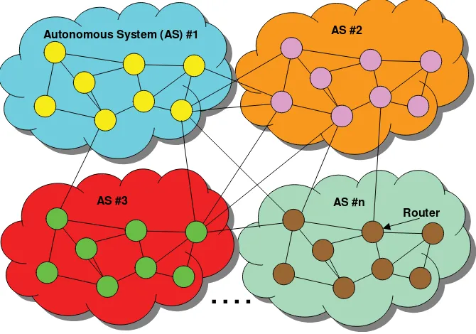
The IP routers, which are operated by a globally unique administrative entity within the Internet community, form an autonomous system (AS) (see Figure 1.1) or border gateway protocol (BGP) domain (RFC 4271 [5]). From a typological standpoint, an AS is composed of a set of routers, thus yielding the distinction between the inner of an AS and the outer of an AS. The outer of an AS is the rest of the Internet.
AS #n AS #3
AS #2 Autonomous System (AS) #1
Router
1.1.2 On the Usefulness of Dynamic Routing Protocols in IP Networks
The deployment of IP networks of large scale (such as those that compose today’s Internet) has rapidly led to the necessity of using dynamic routing protocols, so that routers might determine as efficiently as possible (that is, as fast as possible) the best route to reach a given destination (such an efficiency can be qualified in terms of convergence time).Protocol convergence can be defined as the time it takes for a routing protocol to compute, select, install and disseminate the routing information [that is, the required information to reach a (set of) destination prefix(es)] at the scale of a region, be it an OSPF area or a BGP domain. That is, for a given destination prefix, a converged state is reached when information regarding this prefix has been added/modified or withdrawn in all relevant databases of the routers in the region. Traffic for a ‘converged’ prefix should be forwarded consistently inside the region.
As a matter of fact, static routing reveals itself as being incompatible with the number of IP networks that currently compose the Internet, because the static feeding of the FIB databases (which may therefore contain tens of thousands of entries, as per http://bgp. potaroo.net/) is a tedious task that may obviously impact upon the forwarding efficiency of such IP networks, because of network failures or congestion occurrences. Indeed, static routing leads to ‘frozen’ network architectures, which cannot adapt easily to the aforemen-tioned events, unlike dynamic routing.
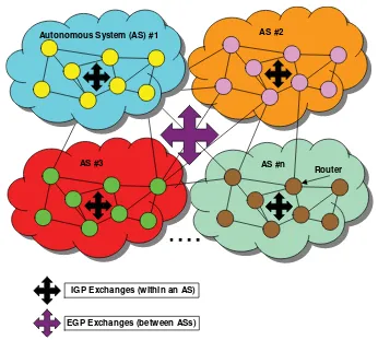
Dynamic routing protocols therefore allow routers to dynamically exchange network reachability information. Such information is stored in the RIB bases of these routers (as mentioned above) and is dynamically refreshed. The organization of the Internet into multiple autonomous systems yields the following routing protocol classification:
dynamic routing protocols making it possible to exchange reachability information about networks that are part of the autonomous system: such protocols are called interior gateway protocols, or IGP;
dynamic routing protocols making it possible to exchange reachability information about networks that are outside the autonomous system: such protocols are called exterior gateway protocols, or EGP.
Figure 1.2 depicts such a classification. Note that the white arrow of the figure should not be understood as a limitation of EGP exchanges that would be restricted to inter-AS communications. As a matter of fact, there are also BGP exchanges within domains.
These dynamic routing protocols use a specific algorithm whose calculation process takes into account one or several parameters which are often called metrics. These metrics are used by the routing algorithm to enforce a routing policy when the administrator of an IP network has the ability to actually define (and possibly modify) the values of such metrics.
Among the most commonly used metrics, one can cite:
the number of routers (hop count metric) to cross before reaching a given destination [the fewer the routers, the better will be the route, whatever the characteristics of the links (in terms of speed, among others) that interconnect the routers];
The nature of the routing algorithms yields another typological effort, which consists in distinguishing the following:
Routing protocols using algorithms based upon distance-vector calculation. Such an algorithm is generally inspired by the Bellman–Ford probabilistic calculation.
Routing protocols using algorithms that take into account the state of the links interconnecting the routers. Such routing protocols are called ‘link-state’ routing proto-cols, and their algorithms are generally based upon the use of the Dijkstra probabilistic calculation.
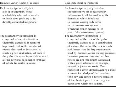
Table 1.1 provides a summary of the principal IGP-specific characteristics of both distance-vector and link-state routing algorithms.
The very first IGP to be specified, standardized, developed and implemented by router vendors was the routing information protocol (RIP) (RFC 1058 [6], RFC 2453 [7]) back in 1984. The route selection process of RIP relies upon the use of a distance-vector calculation, directly inspired from the Bellman–Ford algorithm.
AS #n AS #3
AS #2 Autonomous System (AS) #1
Router
IGP Exchanges (within an AS)
EGP Exchanges (between ASs)
An example of a link-state routing protocol is the open shortest path first (OSPF) protocol (RFC 2328 [8]), which is supported by most of the routers on the market.
1.1.3 On the Inability of an IGP to Address Interdomain
Communication Needs
The organization of the Internet into autonomous systems does not necessarily justify the aforementioned IGP/EGP typology, since the network reachability information exchange between autonomous systems is primarily based upon the use of a dynamic routing protocol, whatever this protocol might be (static routing between ASs is not an option, for the reasons mentioned in Section 1.1.2).
Therefore, why not use an IGP protocol to exchange network reachability information between autonomous systems? Here is a couple of reasons:
1. A router that activates adistance-vector routing protocoladvertizes to its neighbors the whole set of networks it can reach. This information is displayed as a vector list that includes the cost of the path associated with each network. Each router of the network builds its own RIB database according to the information contained in these vector lists, Table 1.1 Comparison between distance-vector and link-state routing protocols
Distance-vector Routing Protocols Link-state Routing Protocols
Each router (periodically but Each router (periodically but also also spontaneously) sends spontaneously) sends reachability reachability information (routes information to all the routers of the to destination prefixes) to its domain to which it belongs directly-connected neighbors. (a domain corresponds either
to the autonomous system to which the router belongs to or part of the autonomous system). The reachability information is The reachability information is
composed of a cost estimation composed of the cost of the paths (generally expressed in terms of (generally expressed as a combination hop count, that is, the number of of metrics that reflect the cost of each routers that need to be crossed to path better than the hop count metric reach a given destination) of each of used by distance-vector routing protocols; the paths that make it possible to reach link-state protocols use metrics that all the networks (destination prefixes) reflect the link bandwidth associated of which the router is aware. with a given interface, for example)
but this information does not provide any clue concerning the identity of the routers and the networks that have to be crossed before reaching a given destination. This may present some difficulty when exchanging such reachability information between auton-omous systems:
The distance-vector routing protocol states that all the routers running it have a common understanding of the metric that allows them to select a next hop rather than another. This common understanding may not be the case for routers belonging to different autonomous systems.
The routing policy that has been defined within an autonomous system might be such that communication with specific autonomous systems is forbidden (e.g. for exchanging specific network reachability information). A distance-vector routing protocol has no means to reflect such filtering capabilities in the vector lists it can propagate.
2. A router that activates a link-state routing protocol advertizes network reachability information which is partly composed of the costs associated with the links that connect the router to adjacent networks, so that each of these routers has the ability to build up a complete image of the network topology. This advertisement mechanism relies upon the use of a flooding capability, which may encounter some scalability issues when considering communication between autonomous systems:
The autonomous systems do not necessarily have a common understanding of the metrics that are used to compute a shortest path, so that the topological information that is maintained by the routers may be dramatically different from one autonomous system to another.
The aforementioned flooding capability of a link-state protocol can rapidly become incompatible with networks of large scale (in terms of the number of routers composing a given domain), especially when considering the traffic volume associated with the broadcasting of network reachability information.
The basic motivation that yielded the specification, the standardization and the develop-ment of routing protocols of the EGP type was based upon the following information: since the metrics used by IGP routing protocols can be understood differently by routers belonging to different autonomous systems, the network reachability information to be exchanged between autonomous systems should rely upon other metrics.
Thus, a router belonging to autonomous system A would advertize to autonomous systems B, C, etc., the networks it can reach, including the autonomous systems that have to be crossed to reach such networks. This very basic concept is used by EGP routing protocols, and it is called ‘path-vector routing’.
An EGP routing protocol has the following characteristics:
The information exchanged between routers that belong to different autonomous systems does not contain any clues about the use of a specific metric, or the value of any cost.
The latter characteristic allows a router to enforce a routing policy that has been defined by the administrator of an autonomous system, so that, for example, this router could decide to avoid using a specific route because this route traverses autonomous systems whose degree of reliability is incompatible with the sensitive nature of the traffic that could use this route.
The forwarding of IP traffic over the Internet implies the crossing of several autonomous systems, thus yielding the activation of an EGP routing protocol. The BGP-4 (border gateway protocol version 4) protocol (RFC 4271 [9]) is currently the EGP that has been deployed over the Internet. The BGP protocol has arisen from the experience acquired during the very first stages of Internet deployment, especially through the deployment of the NSFNET (National Science Foundation NETwork), owing to the specification and the implementation of the exterior gateway protocol (EGP) (RFC 904 [10], RFC 1092 [11], RFC 1093 [12]).
1.1.4 On the BGP-4 Protocol
The principal feature of a BGP-4-enabled router consists in exchanging reachability information about IP networks (aka IP destination prefixes) with other BGP-4-enabled routers. Such information includes the list of the autonomous systems that have been crossed, and it is sufficiently specific for it to be possible to build up an AS connectivity graph from this information.
This AS connectivity graph will help BGP-4-enabled routers in avoiding routing loops (which result in the development of IP network-killing ‘black holes’), and it will also help in enforcing the routing policies that have been defined by the AS administrator.
The BGP protocol relies upon transmission control protocol (TCP) port 179 (RFC 793 [13]) – a transport layer-specific protocol that supports fragmentation, retransmission, acknowledgement and sequencing capabilities.
The BGP communication between two routers can be briefly described according to the following chronology:
The BGP routers establish a TCP connection between themselves by exchanging messages that aim to open this connection, then confirming the parameters that char-acterize this connection.
Once the TCP connection has been established, the very first exchange of (reachability) information is composed of the overall contents of the BGP table maintained by each peer.
Then, information is exchanged on a dynamic basis. This information actually represents specific advertisements every time the contents of one or the other BGP tables have changed. Since the BGP-4 protocol does not impose a periodic update of the global contents of the BGP routing table, each router must keep the current version of the global contents of all the BGP routing tables of the routers with which it has established a connection.
protocol, which waits for the end of the ongoing data transmission before effectively shutting down the connection.
Although the BGP-4 protocol is a routing protocol of the EGP type, routers that belong to the same autonomous system have the ability to establish BGP connections between themselves as well, which yields the following typology:
The connections that are established between BGP routers belonging to different autonomous systems are called ‘external sessions’. Such connections are often named ‘external BGP’ or ‘eBGP’ connections.
The connections that are established between BGP routers belonging to the same autonomous system are called ‘internal sessions’. Such connections are often named ‘internal BGP’ or ‘iBGP’ connections.
iBGP connections are justified by the will to provide (to the BGP routers belonging to the same autonomous system) as consistent a view of the outside world as possible. Likewise, an IGP protocol provides a homogeneous view of the internal routes within an autonomous system.
A BGP route (i.e. the reachability information that is transmitted within the context of the establishment of a BGP connection) is made up of the association of an IP prefix and the attributes of the path towards the destination identified by this prefix. Upon receipt of such information, the router will store it in the BGP routing table, which is actually made up of three distinct tables:
TheAdj-RIB-Intable, which stores all the advertized routes received by a BGP peer. This information will be exploited by the BGP decision process.
TheAdj-RIB-Outtable, which stores all the routes that will be advertized by a BGP peer. These are the routes that have been selected by the BGP decision process.
TheLoc-RIBtable, which stores all the routes that will be taken into consideration by the BGP decision process. Among these routes there will be those that are stored in the Adj-RIB-Out.
The distinction between these three tables is motivated by the BGP route selection process. In practice, most of the BGP-4 implementations use a single BGP routing table, which will be indexed appropriately according to the above-mentioned typology.
1.1.5 The Rise of MPLS
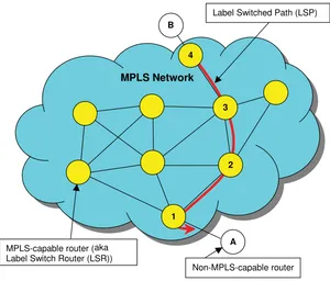
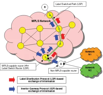
The hop-by-hop IP routing paradigm of the old days of the Internet (as introduced in Section 1.1.1) is being questioned by the multiprotocol label switching (MPLS) technique (RFC 3031 [14]). MPLS is a switching technique that allows the enforcement of a consistent forwarding policy at the scale of aflow, where a flow can be defined as a set of IP datagrams that share at least one common characteristic, such as the destination address.
In this case, all the IP datagrams of a given flow [designated as a forwarding equivalence class (FEC) in the MPLS terminology] will be conveyed over the very same path, which is called a label switched path (LSP) (see Figure 1.3).
to forward traffic over LSP paths. MPLS has been defined so that it can be used whatever the underlying transport technology, or whatever the network layer-specific communication protocol, such as IP. The MPLS forwarding scheme is depicted in Figure 1.4.
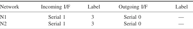
The MPLS forwarding scheme relies upon the maintenance of label tables, called label information bases (LIBs). To forward an incoming MPLS packet, the MPLS-enabled router will check its LIB to determine the outbound interface as well as the outgoing label to use, based upon the information about the incoming interface as well as the incoming label. As per the example provided by Figure 1.4:
Router A of the figure, which does not support MPLS forwarding capabilities, is connected to (or has the knowledge of) networks N1 and N2, which can be reached through its Ethernet 0 (E0) interface. Table 1.2 is an excerpt from its FIB, which basically lists the network prefix, the outgoing interface and the associated next hop router. The black arrow in Figure 1.4 suggests that an ordinary routing update (by means of a
dynamic routing protocol, such as OSPF), advertizes the routes to the MPLS-enabled router [or label switch router (LSR) in the MPLS terminology], which is directly connected to router A.
Using the label distribution protocol (LDP) (RFC 3036 [15]), router 1 selects an unused label [label 3 in the example provided by the excerpt of its label information base below (Table 1.3)] and advertizes it to the upstream neighbor. The hyphen in the ‘Label’ column of Table 1.3 denotes that all labels will be popped (or removed) when forwarding the
MPLS Network
A B
Non-MPLS-capable router MPLS-capable router (aka
Label Switch Router (LSR))
Label Switched Path (LSP)
3
2
1 4
packet to router A, which is not MPLS capable. Thus, an MPLS packet received on the serial 1 interface with label 3 is to be forwarded out through the serial 0 interface with no label, as far as LSR 1 which is directly connected to router A is concerned. The white arrow in Figure 1.4 (between router 1 and router 2) denotes the LDP communication that indicates the use of label 3 to the upstream LSR 2.
LSR 1 has learned routes that lead to N1 and N2 network prefixes. It advertizes such routes upstream. When LDP information is received, router 1 records the use of label 3 on the outgoing interface serial 0 for the two prefixes mentioned previously. It then allocates label 16 on the serial 1 interface for this FEC and uses LDP to communicate this information
E0
Network N1
Network N2
MPLS Network
A B
Non-MPLS-capable router MPLS-capable router (aka
Label Switch Router (LSR)
Label Switched Path (LSP)
3
2
1 4
S0 S1
Label Distribution Protocol (LDP)-based exchange of information
Interior Gateway Protocol (IGP)-based exchange of information
Figure 1.4 MPLS forwarding principle
Table 1.2 Excerpt from the forwarding information base of router A (as per Figure 1.4)
Network Interface
N1 E0
to the upstream LSR. Thus, when label 16 is received on serial 1, it is replaced with label 3 and the MPLS packet is sent out through serial 0, as per Table 1.4.
Note that there will be no labels received by router B (and sent by router 4 in the figure), since the top router B is not an LSR, as illustrated by its routing table (no labels are maintained in this table). The label switched path (LSP) is now established.
Note also that MPLS labels can be encoded as the virtual path identifier/virtual channel identifier (VPI/VCI) information of an ATM cell, as the data link connection identifier (DLCI) information of a frame, in the sense of the frame relay technology, but also as 20-byte long information encoded in the 4-20-byte encoded MPLS header associated with each IP PDU, as depicted in Figure 1.5.
MPLS capabilities are now supported by most of the router vendors of the market, and the technique is gaining more and more popularity among service providers and network operators, as the need for traffic engineering capabilities emerges. Traffic engineering is the ability to (dynamically) compute and select paths whose characteristics comply with requirements of different kinds: the need to make sure that a given traffic will be conveyed by a unique path (potentially secured), e.g. for security purposes, or the need for minimum transit delays, packet loss rates, etc.
MPLS-based traffic engineering capabilities can be seen as some of the elementary components of a global quality of service (QoS) policy.
1.2 Context and Motivation of this Book
IP service offerings (ranging from access to the Internet to more advanced services such as TV broadcasting or videoconferencing) are provisioned owing to the combined activation of different yet complex capabilities, which not only require a high level of technical expertise but also result in the organization of complex management tasks.
Table 1.3 Excerpt from the label information base of router 1 (as per Figure 1.4)
Network Incoming I/F Label Outgoing I/F Label
N1 Serial 1 3 Serial 0 —
N2 Serial 1 3 Serial 0 —
Table 1.4 Excerpt from the label information base of router 2 (as per Figure 1.4)
Network Incoming I/F Label Outgoing I/F Label
N1 S1 3 S0 16
N2 S1 3 S0 16
Label EXP bits Stack Time To Live (TTL)
20 bits 3 bits 1 bit 8 bits
1.2.1 Classifying Capabilities
As stated above, IP services are provided by means of a set of elementary capabilities that are activated in different regions and devices of an IP/MPLS network infrastructure. These capabilities can be organized as follows:
Architecturalcapabilities, which are the cornerstones for the design and enforcement of addressing, forwarding and routing policies. Such policies aim to convey service-specific traffic in an efficient manner, e.g. according to the respective requirements and constraints that may have been (dynamically) negotiated between the customer and the service provider.
Quality of Service(QoS) capabilities, as briefly introduced in Section 1.6. Securitycapabilities, which include (but are not necessarily limited to):
– the user and device identification and authentication means;
– the protection capabilities that preserve any participating device from any kind of malicious attacks, including (distributed) denial of service (DDOS) attacks;
– the means to preserve the confidentiality of (some of) the traffic that will be conveyed by the IP network infrastructure;
– the means to protect users and sites from any kind of malicious attack that may be relayed by the IP/MPLS network infrastructure;
– the functions that are used to check whether a peering entity is entitled to announce routing information or not, and also the features that provide some guarantees as far as the preservation of the integrity (and validity) of such (routing) information is concerned.
Managementcapabilities, composed of fault, configuration, accounting, performance and security (FCAPS) features. Monitoring tools are also associated with such features. They are used for analysis of statistical information that aims to reflect how efficiently a given service is provided and a given policy is enforced.
1.2.2 Services and Policies
The management tasks that are performed to provision and operate an IP network or a set of IP service offerings can be grouped into several policies that define what capabilities should be activated, and how they should be used (that is, the specification of the relevant configuration parameters).
Policies can relate to a specific service [e.g. the forwarding policy to be enforced at the scale of a BGP domain to convey voice over IP (VoIP) traffic with the relevant level of quality], or can be defined whatever the nature of the service offerings (e.g. the BGP routing policy to be enforced within a domain).
The design and the enforcement of a given policy must therefore address a set of elementary questions, as follows:
checked (that is, reliability is a key characteristic of configuration tasks), as well as the dynamic allocation of (network) resources, either proactively (e.g. as part of a global network planning policy) or reactively (e.g. to address traffic growth issues).
What? This is the set of capabilities that are required to enforce a policy, possibly to be inferred by the different services that may be provided. For example, a security policy may rely upon the use of filtering, encryption and firewalling capabilities.
How? This is the set of techniques as well as information (in terms of valued configuration parameters) that reflects the instantiation of a given policy. This is also what this book is about – discussing and detailing the various techniques that can be used dynamically to enforce policies, as well as the provisioning of several examples of services. As an example of an instantiated policy, the QoS policy that needs to be enforced for VoIP traffic may include the explicit identification of such traffic (e.g. by means of a specific DSCP marking), as well as the whole set of configuration arguments (token bucket parameters, actions to be taken by the routers in case of in-profile and out-of-profile traffic, etc.) that define how such traffic is prioritized and forwarded. A specific chapter of this book further elaborates on this example.
Note that timely parameters are also part of this question, like the epoch during which a policy is to be enforced (e.g. 24 hours a day, 7 days a week, etc.). ‘When?’ is therefore the kind of question that is addressed by these parameters.
The design, the provisioning and the operation of a wide range of IP service offerings are therefore the result of the enforcement of a complex combination of policies. Even more complex is the underlying substrate of various technologies that are solicited to provide (from the subscription phase to the actual deployment) and to manage a given service.
The foreseen development of the so-called ‘triple-play’ services, where data, voice and image traffics should be gracefully mixed, provided the underlying network infrastructure has the appropriate resources to convey these different traffics with the relevant level of quality, is another key driver for policy-based management and dynamic provisioning techniques.
1.2.3 The Need for Automation
Needless to say, the provisioning of a wide range of service offerings with the adequate level of quality generally takes time, because policy-based design and management are complex tasks, and also because consistency checks take time: addressing any issue that may result from the operation of conflicting configuration tasks, verifying the accessibility of the service, monitoring its availability and checking the appropriate resources are correctly provisioned on time, etc., are headaches (if not nightmares) for network engineers and operators.
It is therefore generally expected that the introduction of a high level of automation in the service provisioning process as well as the use of dynamic policy enforcement techniques should largely contribute to:
a reduction in the service delivery time;
a reduction in the overall operational expenditures (OPEX) costs associated with the delivery and the exploitation of such services: automation improves production times and is supposed to reduce the risks of false configuration which may jeopardize the quality of the impacted services.
Automation is the key notion that motivated the writing of this book.
1.3 How this Book is Organized
The organization of this book is basically twofold:
The first part deals with the theory, where candidate protocols and architectures for the dynamic provisioning of services and the enforcement of policies within IP/MPLS infrastructures are described in detail.
The second part of the book deals with practice, by introducing and discussing a set of examples [enforcement of QoS and traffic engineering policies, production of BGP/ MPLS-based virtual private network (VPN) facilities, etc.] that aim to convince the reader about the reality of such issues and how dynamic provisioning techniques can gracefully address them.
1.4 What Is and What Should Never Be
This is not a book that aims to promote a ‘one-size-fits-all’ approach, where a single protocol or architecture would address any kind of concern, whatever the nature of the policy, the service and/or the environment.
This is not a book about what is going on in standardization, as far as dynamic provisioning techniques and protocols are concerned.
This is a book that aims to provide readers with a practical yet hopefully exhaustive set of technical updates and guidelines that should help service providers, network operators but also students in acquiring a global yet detailed panorama of what can be done to facilitate (if not automate) the production of services over IP/MPLS infrastructures.
And we sincerely hope you will enjoy it as much as we enjoyed writing it.
References
[1] Postel, J., ‘Internet Protocol’, RFC 791, September 1981.
[2] Perlman, R., ‘Interconnections: Bridges and Routers’, Addison-Wesley, 1992.
[3] Comer, D., ‘Internetworking with TCP/IP. Volume 1. Principles, Protocols and Architecture’, Prentice-Hall, 1995.
[5] Rekhter, Y., Li, T., ‘A Border Gateway Protocol 4 (BGP-4)’, RFC 4271, January 2006. [6] Hedrick, C., ‘Routing Information Protocol’, RFC 1058, June 1988.
[7] Malkin, G., ‘RIP Version 2’, RFC 2453, November 1998. [8] Moy, J., ‘OSPF Version 2’, RFC 2328, April 1998.
[9] Rekhter, Y. and Li, T., ‘A Border Gateway Protocol 4 (BGP-4)’, RFC 1771, March 1995. [10] Mills, D., ‘Exterior Gateway Protocol Formal Specification’, RFC 904, April 1984.
[11] Rekhter, J.et al., ‘EGP and Policy Based Routing in the New NSFNET Backbone, RFC 1092, February 1989.
[12] Braun, H., ‘The NSFNET Routing Architecture’, RFC 1093, February 1989. [13] Postel, J., ‘Transmission Control Protocol’, RFC 793, September 1981.
[14] Callon, R.et al., ‘Multiprotocol Label Switching Architecture’, RFC 3031, January 2001. [15] Andersson, L.et al., ‘LDP Specification’, RFC 3036, January 2001.
[16] Blake, S.et al., ‘An Architecture for Differentiated Services’, RFC 2475, December 1998. [17] Bernet, Y.et al., ‘An Informal Management Model for Diffserv Routers’, RFC 3290, May 2002. [18] Heinanen, J.et al., ‘Assured Forwarding PHB Group’, RFC 2597, June 1999.
2
Basic Concepts
2.1 What is a Policy?
Policy-based management concepts were introduced at the end of the 1990s and were standardized in the early 2000s. The notion ofpolicyis generally associated with the concept of rules with various degrees of abstraction. Policies can reflect a business strategy (e.g. privilege the forwarding of corporate traffic over Internet traffic within a virtual private network), a company-wide set of rules (e.g. access to the Internet is forbidden) or a combined set of network-inferred rules that yield the specification of forwarding, routing, quality of service and/or security policies.
The aforementioned notion of abstraction refers to the definition of a scope of any given policy without explicitly describing it. According to RFC 3198 [1], a policy can be defined as ‘a set of rules to administer, manage and control access to network resources’, where these rules can be defined in support of business goals. The latter can also define policies as a ‘definite goal, course or method of action to guide and determine present and future decisions’.
Policies defined as a set of rules follow a common information model (such as RFC 3060 [2]), where each and every rule defines a scope, a mechanism and actions. An example of such a rule could be: ‘If Internet traffic exceeds 50% of the available bandwidth on the link that connects a VPN site to the network, then limit the corresponding Internet traffic-dedicated resources during certain periods’. In this example, the scope of the policy is the Internet traffic, the mechanism is the bandwidth allocation and the action consists in limiting resources used by Internet traffic during certain periods. This example also introduces the notion of the ‘condition’ that will trigger the application of the rule.
2.2 Deriving Policies into Rules and Configuration Tasks
Policies that are defined by network administrators need to be understood by the (network) devices that will be involved in the enforcement of the corresponding policies. This gives rise to the need for mechanisms that will process the policy-specific information so that such
Service Automation and Dynamic Provisioning Techniques in IP/MPLS Environments C. Jacquenet, G. Bourdon and M. Boucadair
devices can be configured accordingly, that is, with the configuration tasks that will have to be performed to enforce the policy. Policy-based management relies upon the following steps to derive generic policies into configuration information.
2.2.1 Instantiation
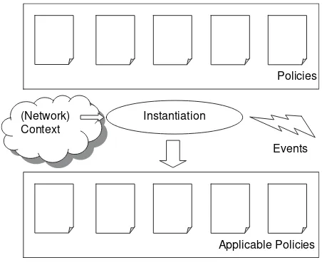
The set of rules that define a policy need to be instantiated according to the environment (e.g. the services to which the policy will be applied) where the policy will be enforced. The policy instantiation can rely upon received events or information that is descriptive of the context (Figure 2.1).
The instantiation process requires:
an understanding of the context-specific information, such as the importance of the mesh in the network, the operating hours, etc.;
the processing of the incoming events (e.g. link failure) and their impact on the policies; knowledge of the information model.
2.2.2 Device Identification
The enforcement of policies needs not only to reflect the applicability of the policies in a given condition but also to identify (and locate) the devices that will participate in the enforcement of the policy. The relationships between the policy and the participating devices are defined in the information model. The actual location of the ‘target’ devices can rely upon the network topology information (as part of the information model), but also on the information depicting the forwarding paths along which traffic will be conveyed in the network.
Policies
Instantiation
Applicable Policies (Network)
Context
Events
The device identification processes require:
knowledge of the scope of action that can be performed by a participating device [e.g. firewalls are not supposed to enforce traffic engineering policies but security policies (based upon the establishment and the activation of traffic filters, for example), while routers may not be solicited to enforce user-specific identification policies, but rather the forwarding policies that will reflect the level of quality associated with the delivery of a given service, as per user requirements];
knowledge of the information model, as well as the (network) topology information.
2.2.3 Translation
Once the policies have been instantiated into a set of applicable policies and the target devices involved in the enforcement of such applicable policies have been defined and identified, the rules defined in the applicable policies need to be translated into device-specific configuration information. This translation process is device-specific to a policy and might be local to the participating device, or use a proxy capability by means of protocols such as the common open policy service (COPS) (RFC 2748 [3], RFC 3084 [4]).
2.3 Storing Policies
The information that depicts a policy needs to be stored and maintained by means of directory services. Directory services have the following characteristics:
They provide a defined syntax for the objects they store, as well as a means to uniquely identify them (notion of distinguished names). Manipulation of the objects accessible through directory services is also defined by means of a set of allowable operations (such as ‘retrieve’ information related to a specific object, ‘modify’ the attributes of an object, etc.).
The information model stored in directory services is hierarchical and often reflects an organizational, function-derived structure. Objects are grouped in branches, and they can have precedence defined by their position in the tree structure.
Directory services rely upon databases that are distributed, yielding slave–master relation-ships. Slave databases partially or totally replicate the information stored in master databases. The master database corresponds to a central repository where policies can be managed in a centralized fashion.
2.4 Policy and Device Configuration
Figure 2.2 reflects the fact that policy-related configuration is centralized, whereas device-specific configuration information is distributed by essence.
2.5 Policy-based Management Model
Both the Internet Engineering Task Force (IETF) and the Desktop Management Task Force (DMTF) have been involved in the specification and the standardization of a policy-based management model, which now serves as a reference for the specification and the enforcement of a set of policies within networking infrastructures. Figure 2.3 outlines the different components that are introduced with this model.
Figure 2.3 depicts the relationships between the following components:
Thepolicy decision point(PDP), where policy decisions are made. PDPs use a directory service for policy repository purposes. The policy repository stores the policy information
…
Policy-derived Device-related Configuration
…
• System Policies • Network Policies • Access
Policies Policy Server
Policy-related
Configuration Directory
Figure 2.2 Policy configuration and policy-derived device configuration
PDP
PEP Policy
Repository
LPDP PIB
Policy server PEP-PDP
Communication Protocol
PEP-embedding Device
that can be retrieved and updated by the PDP. The PDP delivers policy rules to the policy enforcement point (PEP – see below) in the form of PIB elements.
The policy enforcement point (PEP), where policy decisions are applied. PEPs are embedded in (network) devices, which are dynamically configured from the policy-formatted information that has been processed by the PEP. PEPs request configuration from the PDP, store the configuration information in the policy information base (PIB) and delegate any policy decision to the PDP. This is commonly referred to as theoutsourcing mode. PEPs are responsible for deriving policy-formatted information (as forwarded by the PDP to the PEP) into (technology-specific) configuration information that will be used by the PEP-embedding device to enforce the corresponding policies accordingly. Note that PEP and PDP capabilities could be colocated.
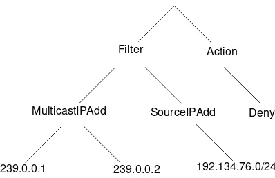
The policy information base (PIB) is a local database that stores policy information. It uses a hierarchical structure, where branches are called policy rule classes (PRCs), and where leaves are called policy rule instances (PRIs). Both PRCs and PRIs are uniquely identified by means of policy rule identifiers (PRIDs). Figure 2.4 provides a generic representation of a PIB structure, and Figure 2.5 gives an example of what a PIB can look like.
Finally, the local policy decision point (LPDP) is often seen as an optional capability (from a policy-based management standpoint) that can be embedded in the device to make local policy decisions in the absence of a PDP. Examples of LPDPs include the routing processes that enable routers to dynamically compute and select paths towards a destination without soliciting the resources of a remote PDP.
The example provided in Figure 2.5 denotes a policy that basically consists in filtering out any multicast traffic sent by any source whose IP address is in the 192.134.76.0/24 range, and which is forwarded on the 239.0.0.1 and 239.0.0.2 group addresses.
PRC
PRC
PRC
PRI
PRI
PRI
2.5.1 Reaching a Policy Decision
When a generic event invokes a PEP for a policy decision, the PEP generates a request that includes information related to the event. The PEP then passes the request with all the relevant policy elements to the PDP. The PDP then reaches a decision, which in turn will be forwarded to the PEP for application purposes.
Within the context of policy-based management, the PEP must contact the PDP even if no policy information is received, to retrieve the configuration information it needs upon bootstrap, for example. Both PDP and PEP should have the ability to send an unsolicited message towards each other at any time (decision change, error message, etc.).
2.5.2 Requirements for a PEP–PDP Communication Protocol
There are several candidate protocols that can be suitable for conveying policy information between PEP and PDP capabilities. This book details the machinery of some of them, such as the COPS protocol (RFC 2748 [3], RFC 3084 [4]), the remote authentication dial-in user service (RADIUS) (RFC 2865 [5]) or the Diameter protocol (RFC 3588 [6]). This section only aims to list basic requirements for such a protocol:
The protocol needs to rely upon a reliable transport mode, to avoid undetected loss of policy queries and responses.
The protocol should add as small an amount of delay as possible to the response time experienced by policy queries, hence stimulating fast processing capabilities.
The protocol needs to support opaque objects to avoid protocol changes every time a new policy object has to be exchanged between a PEP and a PDP.
The protocol needs to support a transactional way of communication, so as to stimulate the query/response formalism, including the ability to renegotiate a previous policy decision.
The protocol should support unsolicited messaging, to allow both PEP and PDP to notify each other whenever a state change occurs.
Communication between a PEP and a PDP should be secured, hence preserving the confidentiality of the information exchanged between both entities.
Filter
MulticastIPAdd
Action
239.0.0.1 239.0.0.2
SourceIPAdd Deny
192.134.76.0/24
References
[1] Westerinen, A.et al., ‘Terminology for Policy-based Management’, RFC 3198, November 2001. [2] Moore, B.et al., ‘Policy Core Information Model – Version 1 Specification’, RFC 3060, February
2001.
[3] Boyle, J., Cohen, R., Durham, D., Herzog, S., Raja R. and Sastry A., ‘The COPS (Common Open Policy Service) Protocol’, RFC 2748, Proposed Standard, January 2000.
3
The RADIUS Protocol and its
Extensions
The Remote Authentication Dial-In User Service (RADIUS) protocol (RFC 2865) is one of the most popular authentication protocols used in operators’ networks. Its success began with the early Livingston implementations, to offer a scalable and centralized solution to authenticate and authorize users, and possibly to report about resource usage for users connected to equipment through a log-in service (like Telnet) or to remote access servers, primarily through public switched telephone network (PSTN) or integrated services digital network (ISDN) infrastructures. Based on Livingston’s early developments, the IETF has standardized its concepts and usage. The last version edited by the IETF is RFC 2865, which is based upon the same concepts than those that were described in the very beginning, but also enhances the protocol to make its implementation more suited to the evolution of remote access usages.
Nowadays, RADIUS is often seen as an obsolete protocol, which is partly true in its conception, as we will see in the next section. However, this judgement has to be moderated, since RADIUS managed to take up most technical challenges imposed by the evolution of access technologies such as large xDSL deployments and secured wireless access (IEEE 802.11i), among others. Mobile phone architectures are also using RADIUS extensively for content billing purposes, even though 3GPP enthroned the Diameter protocol as its successor.
3.1 Protocol Design
RADIUS is based upon a client/server protocol model. The client sends requests to the server, which answers back with appropriate replies depending on the initial request. Regular RADIUS architectures make the Network Access Server (NAS) support the client role, and it queries the RADIUS server as the Authentication Authorization Accounting (AAA) server, as we can see in Figure 3.1.
Service Automation and Dynamic Provisioning Techniques in IP/MPLS Environments C. Jacquenet, G. Bourdon and M. Boucadair
RADIUS exchanges can be split into two different categories: AUTH (AUTHentication/ AUTHorization) messages and accounting messages. The corresponding flows can follow different paths in the network, since purpose and constraints required by these messages are different. AUTH flows require real-time treatment to grant access as fast as possible, whereas accounting messages may be stored in a database for further exploitation, such as billing.
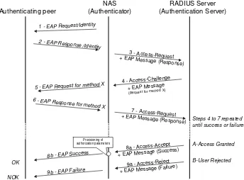
A RADIUS client request is triggered whenever an end-user notifies the NAS that it requires to be connected to the network. This primary notification is performed with any access protocol capable of carrying information between the end-user and the NAS, such as PPP, EAPoL with 802.1X, HTTP or even Telnet. Depending on the complexity of the state machine of the access protocol, RADIUS exchanges might vary. The very basic framework of RADIUS protocol exchanges starts with an Access-Request message, requesting an authentication/authorization on behalf of an end-user, and ends with an Access-Accept message, transmitting all required parameters for this end-user to make use of the net-work, assuming this end-user is entitled to access the network. Otherwise, the RADIUS exchanges will terminate with an Access-Reject message. We will see later that this simple request/response exchange becomes more complicated when used with EAP, for instance.
Accounting message exchanges also follow a regular client/server model, with notifica-tions sent by the RADIUS client to the accounting server, these notificanotifica-tions being acknowledged by the latter.
In order to provide a way to secure RADIUS transactions, both RADIUS client and server might be configured with a shared secret, which is used in response messages (messages from server to client) to ensure message integrity and authenticity, as long as the secret is not compromised. This method does not protect the content of the message itself, but it is still an efficient way to protect a RADIUS client against man-in-the-middle replay attacks. In request messages, the shared secret is only used to encrypt the user’s password.
3.1.1 Protocol Structure and Messages
RADIUS relies upon the UDP protocol, using destination ports 1812 and 1813 for AUTH and accounting messages respectively. The choice of UDP has been regularly debated, since
Access Network (PSTN, ISDN,
ADSL)
RADIUS Client Terminal
NAS Transport Network
RADIUS Server
UDP might appear to be incompatible with the required level of resilience expected by access network operators. UDP has been chosen for different reasons such as its simplicity for RADIUS implementations, and also because UDP is less resource consuming for operating systems by comparison with TCP. As a consequence, RADIUS implementers have been obliged to maintain their own timers for retransmissions, but UDP made it easier to handle backup server switching and to lower CPU consumption. Whatever one’s opinion of this choice, UDP proved its suitability to RADIUS extensive usage.
RADIUS messages consist of five main fields as shown in Figure 3.2:
Code: 8 bits. This field identifies the type of RADIUS message. RFC 2865 defines the different types of message, as listed below:
– Access-Request(code 1); – Access-Accept(code 2); – Access-Reject(code 3); – Accounting-Request(code 4); – Accounting-Response(code 5); – Access-Challenge(code 11).
Identifier: 8 bits. This field is used to identify the message exchange being performed between the client and the server. It is interesting to note that this 8-bit field length imposes a limit of 256 simultaneous requests generated by a client without answers from the AAA server. If 256 requests might appear to give a sufficient cushion to serve all requests, large-scale deployments have shown that it is not always sufficient to bear request bursts (e.g. in the case of massive disconnections).
Length: 16 bits. This field indicates the total length of the RADIUS message.
Authenticator: 128 bits. This field is filled up with a suite of octets generated to ensure authenticity of server-initiated messages during RADIUS exchanges. It is also used to encrypt the user’s password inAccess-Reques