THE 42 VOLT POWER NET ARCHITECTURE STANDARDS
by Emilian Ceuca
Abstract. The automobile is undergoing a revolution in the design of its electrical system. This is the result of increasingly sophisticated engine and body controls, as well as the introduction of new, electrically controlled functions. The main electrical bus of the future will be 42 V, and it will be buffered by a 36 V battery [1,2]. As many devices and electronic control units require voltages different from 42, conversion from the 42 V bus to these other voltages will be necessary. Some anticipated features, such as electromechanical engine valves, will demand both conversion and sophisticated control at power levels in the 2 kW to 10 kW range. These, and other developments in automotive engineering, are promising to create a vital and challenging new market for power electronics in the next decade.
1. INTRODUCTION
Introduction of an array of new electrical and electronic features into future vehicles is generating vehicle electrical power requirements that exceed the capabilities of today's 14 volt electrical systems. In the near term (5 to 10 years), the existing 14V system will be marginally capable of supporting the expected additional loads with escalating costs for the associated charging system. However, significant increases in vehicle functional content are expected as future requirements to meet longer-term (beyond 10 years) needs in the areas of emission control, fuel economy, safety, and passenger comfort. A higher voltage electrical system will be required to meet these future requirements.
the currently available 14V power supply, and a higher voltage supply would definitely be beneficial to some of the existing automotive components. Yet, today's situation is quite different and more complicated than that in 1955. The comparative complexity of today's 14V electrical system and the sheer number of different components that have been designed to operate at 14V make the prospect of changing to any new voltage quite painful. Furthermore, there are some specific components such as incandescent lightbulbs and low-power electronic modules that prefer low voltage operation and appear unlikely to offer any advantages from the introduction of a higher system voltage. It is because of this dilemma that proposals for introduction of a dual-voltage electrical system have been gaining increasing interest throughout the global automotive industry . According to this approach, a new higher-voltage system is introduced to accommodate desired higher power components and features while simultaneously preserving the present 14 volt system – at least for an interim period – for those components that prefer the present lower voltage. An important side benefit of this approach is the natural segregation of the higher-power loads to the higher-voltage bus which provides opportunities for improved voltage regulation of the 14V bus due to the removal of electrically "noisy" components such as motors.
It is only recently that manufacturers have begun to appreciate the electrical system’s influence on vehicle performance and price. The result has been an increasing interest in re-placing mechanical actuators by electrical, improving electrical system efficiency, finding alternatives to the present 14 Vdc system, and improving safety and comfort by introducing new functions that are best controlled electrically. A further, rather interesting, motivation to electrify functions is that electrically driven “things” provide packaging flexibility.
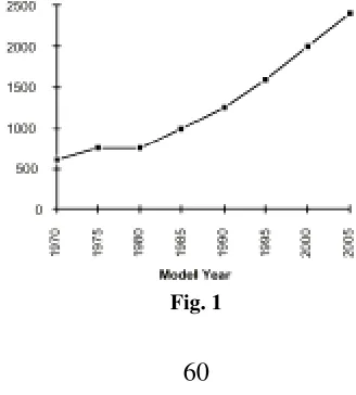
Mechanically driven devices, such as power steering, water pumps and air conditioning, are located on the front of the engine and driven by the “front-end accessory drive” (FEAD). Automotive designers would love to have the styling flexibility provided by eliminating the FEAD. The anticipated increase in average electrical load in a high-end car is shown in below:
Further motivation for a critical assessment and redesign of the electrical system is provided by the US Partnership for a New Generation of Vehicles (PNGV) [3]. This is an aggressive program, co-funded by the US government and the auto industry, to develop an 80 mpg, “green,” automobile. Europe is pursuing an equivalent program to produce a 3 liter car [4]. The target vehicle class is the mid-size sedan, e.g., a Ford Taurus or Chevrolet Lumina. This partnership is now completing its sixth year, and the highly probable design outcome for all three participating OEM’s is a variant of the hybrid. It has also become clear that one of the technologies dominating vehicle cost is power electronics.
In brief, the dual-voltage system is particularly attractive because it simultaneously:
• enables implementation of functionality that cannot be achieved with a 14V supply alone
• offers system benefits associated with implementation of a higher-voltage bus
• maintains 14V for those components that benefit from the lower voltage • imposes a smaller design burden than transforming the entire system to a higher voltage
• reduces the impact on suppliers who have to retool components for higher voltages
The purpose of this paper is to examine the capacity pressures that are building on the present 14V electrical system, followed by a more thorough examination of the advantages offered by the introduction of a dual-voltage 42/14V electrical system as listed above.
2. ELECTRICAL LOADS
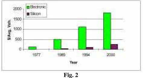
The electrical and electronic content in personal transportation vehicles has grown very significantly during the past two decades, and there is little evidence that it will reach a plateau anytime soon . As indicated below, the electronic content alone of vehicles at the turn of this century is projected to reach nearly US$2000, with silicon chip content representing over 13% of the total. Although it is likely that electrical and electronic content will eventually settle out at some fixed percentage of total vehicle purchase price beyond the near term (2010 to 2020), the impact of the expected load growth during the next several years will undoubtedly have a major effect on the electrical system design.
Fig. 2
This reflects an ongoing trend to introduce new electrically-powered loads that have been converted from existing functions or features that are presently powered either by hydraulics, pneumatics, or direct mechanical connection to the engine shaft. Examples which have already been introduced or are undergoing significant development include electric power steering, electric brakes, electric water pumps, active ride control, and electromechanical (EM) engine valve actuators. Each of these new loads requires power in the range of several hundred watts or higher . Conversion of existing functions and features to electrical power offers valuable opportunities for vehicle performance benefits in such important areas as fuel economy, emissions, and passenger comfort. Electronics provides a potent means of adding "smarts" to vehicle functions so that power is used only when needed (i.e., "on demand") as a means of saving energy. An excellent example of this approach is electric power steering. Today's conventional hydraulic power steering system uses an engine-powered, belt-driven pump to generate the hydraulic pressure. This pump runs continuously, placing a constant power drain on the engine. By converting the steering function to electric power from hydraulics, power is applied only when the steering wheel is rotated, and then only in proportion to the amount of the rotation.
Using the EPA fuel economy cycle, it is estimated that electric power steering can provide a 1 to 3% improvement in fuel consumption depending on vehicle class. For a vehicle that averages 9 l/100 km (25 mpg), this is an improvement of 0.11 to 0.32 km/l (0.25 to 0.75 mpg).
3. WIRING HARNESS
Fig. 3
These statistics are driven by the predominantly point-to-point configuration of today's electrical system network. The vehicle's wiring complexity continues to increase as new electrical loads are added, despite a long-standing desire by automotive manufacturers to find ways to simplify the wiring harness in order to reduce cost and improve reliability. The prospect of new high-power loads with ratings exceeding 1 kW is particularly disturbing for electrical system designers because of the large wire sizes needed to handle the associated high currents at 14V, adding significantly to the weight and cost.
Introduction of a higher voltage bus supports the long-term objective of simplifying the wiring network in at least two ways. First, there is an important opportunity to reduce the wire harness weight and cost by reducing the wire size. For example, delivering the same power at 42V requires only one-third of the current required at 14V, opening the way for use of smaller, lighter weight wires on all of the vehicle's higher power lines as shown above. The value of this conversion is somewhat limited in today's vehicles since many of the wires for existing low power loads are already constrained to a minimum size in order to provide sufficient mechanical strength. As a result, conversion of a large sedan from 14V to a dual-voltage 42/14V system is projected to yield a wiring harness savings of only approximately US$15 and 4 kg.
switching networks in future electrical systems, streamlining the wiring network needed to supply tomorrow's higher-power loads.
4. CHARGING SYSTEM
5. THE PRESENT ELECTRICAL SYSTEM
The present electrical system employs a 12 V lead-acid battery for energy storage and power capability, thus creating a network with a nominal voltage of 14.4 V with the engine on. A conceptual diagram of the system is shown in below:
Fig. 4
Not shown in this diagram are the details of the electronic control units (ECUs) comprising microprocessors and MOSFET switches to control the engine, transmission and many other functions requiring a response to sensor inputs. Perhaps the most significant of these from a power electronics point of view is the antilock braking system (ABS). Hydraulic valves are rapidly actuated by power MOSFET switches in response to brake pedal pressure. Originally conceived to prevent brake lock-up, the ABS control system is now used routinely to provide traction and dynamic stability controls. It is an excellent example of how electronics, and particularly power electronics, has made possible significant performance and safety improvements in the car. A typical high-end car, e.g., a Lincoln Continental, contains over 50 fuses, a midsize car contains over 40, and a Jaguar contains 80. These fuses are incorporated in two or more junction boxes placed in accessible locations within the engine and/or passenger compartments. In addition to fuses, these junction boxes often contain relays, and are an expensive and complex component of the electrical system.
rate (full alternator output), and a battery terminal connector suddenly coming loose. The alternator field current cannot be instantly reduced, so the alternator’s voltage behind reactance, which can exceed 100 V under these conditions, appears at its terminals. Such a transient is shown below:
Fig. 5
The car’s entire electrical system (excluding the now disconnected battery) is subjected to this transient. Some mitigation of the transient is provided by avalanche diodes in modern cars, but a maximum system voltage of 40–60 V is still assumed for design purposes. Power semiconductor devices, e.g., those used as relay drivers or in the ABS, are thus typically rated for 60 V even though the nominal system voltage is only 14 V. The voltage is measured at a tail lamp. The initial spike is the alternator L(di/dt) voltage, while the longer transient is due to the decay of the alternator field.
6. THE 42 V ARCHITECTURES
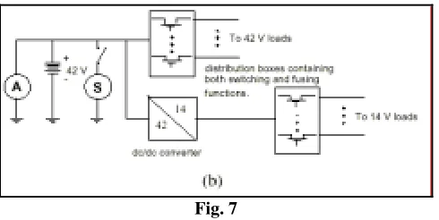
The structure of the 42 V electrical system is still fluid, and it is not clear that there will be an industry standard. Two practical alternatives being seriously considered by OEMs are shown in next figures.
Figure (a) shows a dual battery system, while Fig. (b) illustrates an architecture using only a single 42 V battery. Each of these designs has advantages and disadvantages with respect to cost, reliability and flexibility, due mostly to the different requirements placed upon the power electronics in each. A common feature of both is the presence
of a 14 V network. While some manufacturers are exploring the practicality of a comprehensive 42 V network, the present 14 V supply and service infrastructures present a formidable challenge.
The philosophy behind the dual battery system, Fig. (a), is that the starting function should be isolated from the storage function required for “key-off” loads. These are the electrical loads drawing power when the ignition is off, e.g., keyless entry, theft alarm, clock. These loads are sufficient to drain the battery in today’s car when left parked for long periods, for example, at an airport for several weeks.
Fig. 7
In contrast, the single battery architecture of Fig. (b) is based upon the desire to avoid the cost, weight and packaging problems created by a second battery. The philosophy here is that the energy management system will be smart enough to monitor the single battery and manage the key-off loads to prevent depleting the 36 V battery to the point where the car cannot be started.
7. CONCLUSION: APPLICATIONS WITH HIGHER SUPPLY VOLTAGE Several vehicle manufacturers already have very specific ideas concerning the timescale for an additional 42V power system. Consequently, countless automobile suppliers worldwide are working on proposed solutions for generating, storing and distributing electrical power at a nominal supply voltage of 42V. Prominent applications include starting and generating, in some cases also combined, power DC/DC converters, power steering, as well as drive arrangements for various motors, such as radiator fans, but also the switching of simple thermal resistances. In order to implement all these ideas, protected or unprotected power switches with a dielectric strength of approximately 60-70V are required.
On the other hand, there are many other applications in the automobile sector which operate at highernominal supply voltages. Firstly there are the 24V truck applications employing a 24V generator and a24V battery, with similar load dump problems to those of today’s 14V automobile electrical system. Ahigh degree of electronification is discernible in the truck sector, together with a strong demand for smartpower switches with a dielectric strength >65V.
In addition, there are applications in which a higher voltage is generated locally by means of DC/DC converters. Typical of these applications is fuel direct injection where the high voltage is used to achieve a rapid injection valve response. This requires smart power switches with a dielectric strength of e.g. >80V.
REFERENCES
[1] Kassakian, J. G., H. C. Wolf, J. M. Miller and C. J. Hurton, Automotive Electrical Systems circa 2005, IEEE Spectrum, Aug. 1996, pp. 22- 27.
[2] Miller, J.M., et al., Making the Case for a Next Generation Automotive Electrical
System, IEEE-SAE International Congress on Transportation Electronics
(Convergence),Dearborn, MI, Oct. 1998.
[3] Review of the Research Program of the Partnership for a New Generation of Vehicles, Fifth Report, National Research Council, National Academy Press, 1999.