ACCURACY EVALUATION FOR A PRECISE INDOOR MULTI-CAMERA
POSE ESTIMATION SYSTEM
C. Götz, S. Tuttas, L. Hoegner, K. Eder, U. Stilla
Photogrammetry and Remote Sensing, Technische Universitaet Muenchen, Arcisstraße 21, 80333 Munich, Germany
carsten.goetz@bv.tum.de, stilla@tum.de
Working Groups III/1, III/5
KEY WORDS: Close Range, Industrial, Pose Estimation, Accuracy
ABSTRACT:
Pose estimation is used for different applications like indoor positioning, simultaneous localization and mapping (SLAM), industrial measurement and robot calibration. For industrial applications several approaches dealing with the subject of pose estimation employ photogrammetric methods. Cameras which observe an object from a given point of view are utilized as well as cameras which are firmly mounted on the object that is to be oriented. Since it is not always possible to create an environment that the camera can observe the object, we concentrate on the latter option. A camera system shall be developed which is flexibly applicable in an indoor environment, and can cope with different occlusion situations, varying distances and density of reference marks. For this purpose in a first step a conception has been designed and a test scenario was created to evaluate different camera configurations and reference mark distributions. Both issues, the theoretical concept as well as the experimental setup are subject of this document.
1. INTRODUCTION 1.1 Motivation
Nowadays quality control in the view of geometric accurateness is an essential task in industrial manufacturing. According to a survey accomplished in 2009 by the Fraunhofer-Allianz Vision (Sackewitz, 2009), about 85% of German companies in the automotive industry employ 3D measurement techniques for different tasks. About 40% of them are using optical measurement systems or systems combined with them. For achieving highly accurate results in an absolute coordinate system, the pose of the measurement device must be known very precisely. Subject to certain conditions, determining these orientation parameters is feasible without greater efforts by means of additional sensor systems. An operable but cost-intensive solution would be the use of a laser tracker in combination with a six degrees of freedom (6DOF) tracking device. If the measurement task cannot comply with the necessary conditions, conventional solutions will not be applicable.
In literature the task of determining the orientation of an object is related to the problem of pose estimation. During the last two decades many articles have been published about photogrammetric approaches dealing with pose estimation. It is subject of various applications ranging from pose detection of persons, localization of vehicles to industrial applications. Only a brief choice will be mentioned here to show the diversity in which pose estimation could be used.
Hahn et al. (2010) present a method for tracking the spatio-temporal 3D pose of a human hand-forearm. Willert (2010) developed an approach to determine a person’s position within a building using an image taken by a cell phone. An overview about optical systems for indoor self-positioning in general is given in Mautz & Tilch (2010). Their own system uses a set of projected laser points which are detected by a digital camera. Beyond indoor applications Muffert et al. (2010) investigated
the quality of the spatial trajectory of a mobile survey vehicle from images recorded by an omnidirectional camera system. Another approach that exploits image sequences is introduced by Chen & Schonfeld (2010). To estimate an object’s pose from multiple cameras they firstly derived a solution for only one camera employing a feature based method and extended it for multiple cameras.
Another field of research is the so called ‘simultaneous localization and mapping’ (SLAM). Early work pursuing different methods has been published by Facchinetti et al. (1995) and Wells et al. (1996). More recent developments can be found in Mouragnon (2006), who improved accurateness and speed of the localization and mapping of a moving vehicle by a local bundle adjustment. In addition Lemaire (2007) conducted a comparison between an algorithm that relies on monocular vision and a solution using stereovision observations. In Linkugel & Bobey (2010) a stereovision approach employing the Speeded Up Robust Feature Algorithm (SURF) is used for detection of artificial and natural landmarks. Gupta & Jarvis (2010) showed the feasibility of a localisation system for a mobile robot based on a camera with optics providing a field of view of 180°.
Further publications concentrate on industrial measurement and robot calibration. For the latter photogrammetric approaches have already been proposed in the 1990s (Albada et al., 1995; Maas, 1997). Hefele & Brenner (2001) examined the calibration done by a target board mounted to the robot and a camera placed at a fixed position as well as vice versa. Aside of applications where the industrial robot itself is of interest, pose estimation is used in conjunction with measurement devices (Sahrhage et al., 2006; Aicon3d, 2011).
Throughout all these different fields like indoor applications, SLAM and industrial applications a contradiction exists between the demand for large measurement volumes and high accuracy. So the solution for the estimated pose is a compromise with respect to the intended application.
We aim to develop a camera system for industrial applications which is able to determine its pose with submillimeter accuracy but which is useable within a range of several meters. For that purpose we plan to establish a coordinate system composed of precisely measured coded reference targets. Possible cases of application can be seen for example in processes like industrial assembly, quality control, the foresaid robot calibration or the precise alignment of tools, which are fixed on such a pose estimation system. This paper describes a concept as well as the description of a first test setup whose results will allow the evaluation of different adjustment models.
1.2 Related Work
One possibility to classify the approaches is to group them in terms of the state of motion of the pose determining sensor. The first type would be any kind of external sensor, which operates at a fixed position observing an object’s pose in a constant direction. For example Sahrhage et al. (2006) follows this concept utilizing a stereovision camera system. Schütze et al. (2010) propose a camera frame consisting of four sensors observing an active target carried by a robot. Their approach could improve the absolute positioning accuracy of the robot by a factor of 20 compared to the accuracy without any further means. The disadvantage of methods which estimate an object’s pose by an external sensor is that it can hardly cope with randomly occurring occlusions, except a high redundant number of sensors is used.
The second type of pose estimating sensors can be seen in systems mounted directly on the object for which the pose has to be determined. Muffert et al. (2010) has mounted the omnidirectional camera system Ladybug 3 (Point Grey, 2011) on a mobile survey vehicle. The computation of the spatial trajectory is done from the parameters of orientation and position calculated from image sequences. As they do not bring in any pass-point information, an absolute orientation cannot be carried out.
In the field of industrial applications, the handheld probe Aicon ProCam (Aicon3d, 2011) can also be mentioned. But there is the limitation, that its measurement tip is only used to measure the coordinates of a single point and not a complete pose. The precision is specified to be 0,1mm + 0,1mm/m depending on the distance to the reference board.
Luhmann (2009) carried out an investigation on the theoretical precision of the measurement of position and orientation of an object in 3D space with respect to a reference system using a single camera. He uses two space resections, one for the transformation between camera and reference field and one for the transformation between camera and (moving) object. Although his explanations are related to the first type (sensor not in motion), one could imagine the camera being fixed to the moving object and adapt the procedure.
Frahm et al. (2004) developed an approach to estimate the pose of a multi-camera system. They assume for the system that the cameras have fixed orientations and translations between each other. Their method is applicable even in the case of non-overlapping views of the cameras. A technique to estimate the relative orientation of all the mounted cameras directly from the image sequence itself is also given.
A similar approach is that of Muhle et al. (2008). They describe a process to determine the relative orientation of two rigidly connected stereo camera systems. But both of the last-mentioned methods do not concentrate on determining an accurate pose under industrial conditions, which is the aim of our approach.
None of the approaches mentioned above does simultaneously meet the requirements for a system that can achieve a high accuracy despite randomly occurring occlusions at relatively low costs.
1.3 Overview
In section 2 of this article the demanded properties for the future pose estimation system are derived. First we sketch a coarse application scenario, and then we give an overview of the steps that have to be executed during the process. Section 3 deals with a first experimental setup, which has been designed to investigate the potential of the utilized hardware and to give verification for theoretically derived results. In section Fehler! Verweisquelle konnte nicht gefunden werden. the steps for a following data processing are drafted. Section 5 contains a brief discussion of the experiment. At least, in section 6, a perspective to future work and studies in this field is mentioned.
2. SYSTEM SETUP 2.1 Requirements
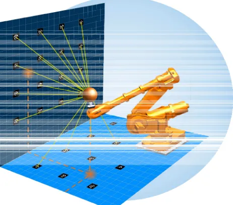
The photogrammetric pose estimation sensor to be developed should utilise coded reference targets to determine its absolute pose within a global coordinate system. The main principle of the approach is illustrated in Figure 1. The sensor shall be flexibly applicable in an indoor environment and shall cope with different occlusion situations, varying distances and density of reference marks. To this we examine possible configurations of such a measurement device and a setup of reference targets for evaluating the accuracy potential.
Figure 1. Pose estimation by a camera system observing surrounding reference targets.
A basic condition is, that the position at which an exact pose has to be determined, is controlled by other processes. That means that the position can be far from being optimal to determine the absolute pose in a best way. It is also not assured that there is a homogenous distribution of reference marks available since there could be limited possibilities to place them in the surrounding area. So our measurement device has to determine a precise pose, even in the case of larger occluded parts in one or more of the images.
The intended accuracy should be better than 0.2 mm for the absolute positioning within the established coordinate system of the tool used by a robot or in a more general view the robot’s tool centre point. As mentioned before, this accuracy has to be achieved during suboptimal measurement conditions (occlusions, different light situations) and within a typical measurement volume of about 8x8x5 m³.
These requirements reflect a scenario of an industrial robot at a production line equipped with tools that need to be applied very precisely or carrying any other type of measurement device for quality control. In both situations the object to be worked at can have a different shape, can be located at varying places or even be in motion and occlusions of reference targets can occur very often.
As one cannot predict the visibility of reference marks (in cause of occlusion), the selection of hardware components is a compromise between the field of view and the accuracy of the target measurement within the acquired images.
Concerning the optics, a short focal length increases the chance to image any of the coded reference targets but also reduces the size of the target in an image. The latter will lead to a worse image measurement or even to the circumstance, that a target cannot be measured at all. Within this context also fisheye lenses must be evaluated in a further step, as their hemispherical view would open up a construction of a sensor which gives nearly a full field of view by comparatively low costs. Beyond that, the optics should be of compact dimensions, of low weight and offer the possibility to fix aperture and focus in a stable manner.
Concerning the requirements to the camera it can be said, that a high resolution will be helpful to detect targets and their codes respectively. But it must be considered, that the sensor size also affects the field of view. In addition, for the use in an industrial environment a compact and robust camera body is also important. Especially dust and - depending on the use of the system - affecting acceleration forces must not impair the cameras.
These considerations would lead to a compact multi-camera system which can provide a precise position, even if one (or more) cameras are not able to see reference marks. The advantage compared to approaches using an external pose estimation system is, that there is a chance to compute the pose even in situations, where the line of sight is blocked by any other object.
2.2 Concept
In a first step, the pose of the sensor is estimated only by the use of coded reference targets, whose coordinates are precisely known in a global coordinate system. At any position within that reference field, each of the n used cameras acquires an image (Figure 2, see A). The interior orientation parameters of each camera are assumed to be known and stable over the time that is needed for one specific task. Furthermore the cameras are fixed on a stable platform, so that their relative orientation can be determined in advance and will remain constant. The circular centres of the reference targets are measured automatically. Since the orientation of all targets is known, a correction can be added to the image coordinates of a target centre if the target is too close to the sensor. This reduces errors caused by the divergence of the true target centre and the centre of the measured ellipse (Dold, 1996). To compute an adequate set of exterior orientation parameters for each image, a closed form solution for space resection will be applied (Rohrberg, 2009) in conjunction with the RANSAC algorithm (Fischler &
Bolles, 1981) depending on the total number of recognized targets.
With the obtained values, which are considered as initial values, a check can be made to verify the target codes recognized. If a code cannot be validated, the affected target has to be excluded from further processing. If a specific probability exists, that a certain other code belongs to that target, it depends on the remaining detected targets, if that code is assigned to the doubtful target or if the target is just rejected.
Figure 2. Process overview. System at stage 1 (see A) which will be extended to a stage 2 to use feature tracking for supporting pose estimation (B).
Afterwards the parameters are refined by an adjustment approach using only the validated subset of recognized reference marks. This yields information about the variances of the determined parameters and can be used for a quality evaluation. If a camera is not able to be oriented with a sufficient accuracy, its measurements can be excluded from the final bundle adjustment.
In a second step, the system will be extended to improve the stability of the results in difficult situations (Figure 2, B). It is intended to support the pose estimation process by tracking extractable features if not enough coded reference marks are visible. In such a situation a process needs to be introduced to support the decision whether the orientation of a camera based on feature tracking can enhance the final result or if the information must be rejected.
3. FIRST EXPERIMENTAL SETUP 3.1 Purpose of the experiment
The purpose of the experiment is to obtain a dataset from which the pose of two cameras can be computed in various combinations. This will reveal the potential for determination of the exterior orientation of the selected hardware with special attention to the translations and point out the advantages of different configurations. With a configuration the arrangement of the cameras, precisely said their distance and their relative orientation is meant. A second aspect is the verification of computations which shall simulate the same configuration as the real tests.
3.2 Experimental Setup
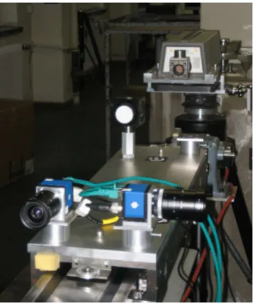
Two very compact industrial cameras are mounted on a platform (Figure 3), which is moveable along a linear slide rail. The change of the coordinates in linear direction can be verified by the measurement with a laser interferometer as a reflector is also mounted on that platform.
Figure 3. Cameras in orthogonal configuration on platform. The movement is measured by a laser interferometer.
The cameras are directly connected to a PC via a Gigabit-Ethernet adapter using their GigE vision interface. We use two CCTV optics having a different focal length of 6.1 mm and 8 mm respectively with the cameras. The laser interferometer is able to resolve a movement of the platform in linear direction with 1/10 µm. The position’s differences can be determined with an accuracy of 2-3 µm. The largest limiting factor is the registration of the atmospheric conditions. Nevertheless for our accuracy requirements it is sufficient that temperature and pressure are determined at one single position. It can be assumed that the environmental conditions are constant for the duration of the experiment. The following Table 4 summarizes the hardware used for the experiment and a schematic layout of the experiment is depicted in Figure 9.
Item Properties
Camera(s) SVS-Vistek SVCam eco655 2448 x 2050 pixel
3.45 µm pixelsize monochromatic CCD GigE Vision interface
Optics VS Technology CCTV
1 SV-0614H, f = 6.1 mm 1 SV-0814H, f = 8 mm Laser interferometer HP 5519A
Table 4. Utilized components.
The reference coordinate system is defined by installing circular coded targets on the wall and on several stable auxiliary constructions. Different diameter sizes are used to realize measurements on varying distances. The coordinates for a basic
network of 80 coded marks were measured with the Kern ECDS, which resulted in a mean RMS of 0.10 mm and a standard deviation of 0.077 mm. The network is complemented with additional 50 marks for the first of the two scenarios and further 200 different for the second scenario (see section 3.3). These reference points are included into the basic network via images, taken by a photogrammetric camera (NIKON D3).
3.3 Procedure
The experiment is divided into two parts which simulate two different scenarios. The first acquisition situation deals with marks in distances from 2 m up to 9 m (Scenario I) and afterwards an acquisition situation with a larger number of smaller marks within short distances of around 1.2 meters (Scenario II) (see Figure 5) is tested.
Figure 5. Reference targets in scenario (II)
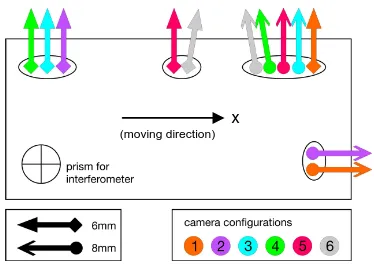
Different sets of configurations of the camera mounting are carried out. Five configurations are realised in scenario I and six configurations in scenario II. The configurations are depicted in Figure 6 and Figure 7, respectively. Each pair of equally coloured arrows shows one specific configuration for the two used cameras. The shape of the arrowhead denotes the focal length of the optics which was mounted on the camera.
Figure 6. Camera configurations for scenario (I). Each pair of equally coloured arrows denotes a configuration, arrowheads show the used optics.
For scenario I the camera platform is moved to four positions for image acquisition, whereas in scenario II only three positions are taken into account. In Table 8 the mean positions with the related RMS error for all camera configurations are shown. An example for an acquisition situation is depicted in Figure 9.
x
z y
x (moving direction)
Figure 7. Camera configurations for scenario II. See expla-nation of Figure 6.
Scenario Position number
Position on linear axis [mm]
RMS [m]
I 1 -0.0186 9.6
2 684.0687 6.7
3 2437.7995 8.8
4 2868.9189 3.4
II 1 2711.2399 1.5
2 2801.4716 2.5
3 2868.9116 2.5
Table 8. Number of positions and distances for image acquisition.
Figure 9. Schematic layout of the experiment and example for image acquisition with configuration 2 at position 3. Values bear on the measurements of the laser inter-ferometer.
4. PROCESSING
The following two analysis strategies are intended for the acquired images: Space resection with a single camera and bundle adjustment using both cameras with overlapping images as well as non-overlapping images.
Furthermore the combination of images taken from cameras in different configurations is planned to simulate a camera setting with more than the actually used two cameras. For this purpose, the positions for image acquisition along the linear slide rail must be met very precisely (see Table 8). The repeatability of a certain position for the carriage, which has to be adjusted manually, is in the range of 10 m. It must be shown, if this is sufficient for the appropriate merging of the different configurations. Additional variations arise from the fact that cameras with different focal lengths are used.
Since the cameras do not provide an automatic exposure measurement and the illumination situation is expected to be
very variable at the test location, an exposure series with constantly increasing exposure time is acquired at every position. This series covers exposure times from 50 ms to 200 ms with an interval of 25 ms.
Data processing will be done in two steps. First the coordinates of all reference targets have to be determined. Incorrectly assigned target codes and outliers have to be corrected or eliminated manually. In a second step, the exterior orientation parameters will be computed within a bundle adjustment exploiting every reasonable combination of the above mentioned variations of image acquisition. In addition occlusions will be simulated by deleting different image measurements from the vector of observations.
The results thus obtained, more precisely the positions of the camera's projection centres, will then be compared to the measurements done with the laser interferometer. For that, coordinate differences between two acquisition positions must be calculated.
Parallel to the data analysis of the experiment a computation derived from a geometrical model of the scene will be done. The aim is to verify the theoretical results with the results from the real test.
5. DISCUSSION
The aim of this first experiment is to obtain 3D coordinates of a rigid camera platform within an absolute coordinate system. For this purpose two cameras with different optics were available only. From a practical point of view this circumstance implies a differing imaging geometry depending on the direction of motion relative to the reference coordinate system (along or across the optical axis), which could be seen as a disadvantage. On the other hand this allows considering a larger number of configurations.
6. FUTURE WORK
A next step would be to extend the experiment in a way that camera orientation angles can be measured and evaluated as well, since according to the experimental setup described in this paper it is only possible to examine a shift.
Further investigations will be made in the field of appropriate reference targets. In cases of partly occluded centres of the circular reference marks, their coordinates cannot be determined correctly anymore. Maybe a reference target could be helpful, that allows the computation of the centre in an additional way. A centre point definition by two crossing lines could be imaginable. An additional advantage would be that the influence of a displaced ellipse centre could be directly measured. This investigation involves, that a decision must be made during the image measurement, to which extraction algorithm a priority is given.
Also a process has to be developed, that a flexible extension of a core reference field is possible. As the first tests have shown, it is often necessary to densify the reference field in some situations. To do this, the user should not be dependant of the availability of another photogrammetric system.
To overcome the problem of occlusions, further test will be made with fisheye lenses. This investigation shall clarify, how far the advantage of a large field of view can compensate the reduction of size of the imaged features. Beyond that a question is how the large distortions at the image margins will allow the recognition of target codes or influence the precision of target measurement at all.
x (moving direction)
Since at every stop of the camera platform a series of images with different exposure times has been taken, an algorithm has to be implemented, that selects the image measurement of the image, where a certain reference mark is exposed optimal. Furthermore, it needs to be investigated how the additional images can be combined to gain a higher accuracy in the performed image measurements. To obtain a statement for this, the influence of the exposure state on the measured image coordinate needs to be investigated.
ACKNOWLEDGMENTS
We would like to thank the Lehrstuhl für Geodäsie of Technische Universität München for providing us their measurement laboratory and especially Dr. Wasmeier and his team for establishing the basic reference system.
This research is funded by the BFS (Bayerische Forschungsstiftung) within the contract number AZ-876-09.
REFERENCES
Aicon3d, 2011. Product description for the ProCam active probe. http://www.aicon3d.de/produkte/moveinspect-techno logy/procam/auf-einen-blick.html (accessed 9 May 2011)
van Albada, G.D., Lagerberg, J.M., Visser, A., Hertzberger, L.O., 2007. A low-cost pose-measuring system for robot cali-bration. Robotics and Autonomous Systems, 15(3), pp. 207-227.
Chen, C., Schonfeld, D., 2010. Pose estimation from multiple cameras based on Sylvester's equation. Computer Vision and Image Understanding, 114(6), pp. 652-666.
Dold, J., 1996. Influence of Target Size on the Results of Photogrammetric Bundle Adjustment. In: Proceedings of the ISPRS Commission V Congress, Vienna, Austria, Vol. XXXI, Part B5, pp. 119-123.
Facchinetti, C.; Tièche, F. & Hügli, H., 1995. Self-Positioning Robot Navigation Using Ceiling Image Sequences. In: Proceeding ACCV'95 (Asian Conference on Computer Vision), Singapore, Vol. 3, pp. 814-818.
Fischler, M.A., Bolles, R.C., 1981. Random sample consensus: A paradigm for model fitting with applications to image analysis and automated cartography. Communications of the ACM, 24(6), pp. 381-395.
Frahm, J.-M., Köser, K., Koch, R., 2004. Pose Estimation for Multi-camera Systems. In: Lecture Notes in Computer Science Vol. 3175: Pattern Recognition, Springer, 2004, pp. 286-293.
Gupta, O. K., Jarvis, R., 2010. Robust pose estimation and tracking system for a mobile robot using a panoramic camera. In: Proceedings of the 2010 IEEE Conference on Robotics, Automation and Mechatronics (RAM), Singapore, pp. 533-539.
Hahn, M., Krüger, L., Wöhler, C., Sagerer, G., Kummert, F., 2010. Spatio-temporal 3D Pose Estimation and Tracking of Human Body Parts in an Industrial Environment. In: Photogrammetrie - Laserscanning - Optische 3D-Messtechnik: Beiträge der Oldenburger 3D-Tage 2010, Wichmann, 2010, pp. 158-170.
Hefele, J., Brenner, C., 2001. Robot pose correction using photogrammetric tracking. In: SPIE Proceedings: Machine Vision and Three-Dimensional Imaging Systems for Inspection and Metrology, Vol. 4189, pp. 170-178.
Lemaire, T., Berger, C., Jung, I.-K., Lacroix, S., 2007. Vision-Based SLAM: Stereo and Monocular Approaches. International Journal of Computer Vision, 74(3), pp. 343-364.
Linkugel, T., Bobey, K., 2010. Visuelle Positions- und Bewegungsbestimmung eines autonomen Systems. In: Photogrammetrie - Laserscanning - Optische 3D-Messtechnik: Beiträge der Oldenburger 3D-Tage 2010, Wichmann, 2010, pp. 195-201.
Luhmann, T., 2009. Precision potential of photogrammetric 6DOF pose estimation with a single camera. ISPRS Journal of Photogrammetry and Remote Sensing, 64(3), pp. 275-284.
Maas, H.-G., 1997. Dynamic photogrammetric calibration of industrial robots. In: SPIE Proceedings Videometrics V, San Diego, Vol. 3174, pp. 106-112.
Mautz, R., Tilch, S., 2010. Innenraumpositionierung mit optischen Methoden. Allgemeine Vermessungs-Nachrichten, 2010(7), pp. 250-255.
Mouragnon, E., Lhuillier, M., Dhome, M., Dekeyser, F., Sayd, P., 2006. Monocular Vision Based SLAM for Mobile Robots. In: Proceedings of the 18th International Conference on Pattern Recognition (ICPR'06), Hong Kong, Vol. 3, pp. 1027-1031.
Muffert, M., Siegemund, J., Förstner, W., 2010. The estimation of spatial positions by using an omnidirectional camera system. In: Proceedings of the 2nd International Conference on Machine Control & Guidance), Bonn, Germany, pp. 95-104.
Muhle, D., Abraham, S., Heipke, C., Wiggenhagen, M., 2008. Automatische Orientierung von zwei gemeinsam bewegten Stereosystemen ohne gegenseitige Korrespondenzen. In: Photogrammetrie - Laserscanning - Optische 3D-Messtechnik: Beiträge der Oldenburger 3D-Tage 2008, Wichmann, 2008, pp. 186-193.
Point Grey, 2011. Product description for the Ladybug3 spherical digital video camera system. http://www.ptgrey.com/ products/spherical.asp (accessed 9 May 2011)
Rohrberg, K., 2009. Geschlossene Lösung für den räumlichen Rückwärtsschnitt mit minimalen Objektinformationen. In: Photogrammetrie - Laserscanning - Optische 3D-Messtechnik: Beiträge der Oldenburger 3D-Tage 2009, Wichmann, 2009, pp. 332-339.
Sackewitz, M., 2009. Marktstudie 3-D-Messtechnik in der deutschen Automobil- und Zuliefererindustrie. Marktstudie, Fraunhofer-Allianz Vision, Erlangen, Germany.
Sahrhage, V., Riede, R., Luhmann, T., 2006. Optische 3D-Navigation von Sensoren. In: Photogrammetrie - Laserscanning - Optische 3D-Messtechnik: Beiträge der Oldenburger 3D-Tage 2006, Wichmann, 2006, pp. 54-61.
Schütze, R.; Boochs, F.; Raab, C.; Wirth, H., Meier, J., 2010. Ein Mehrkamerasystem zur exakten Positionsbestimmung von beweglichen Effektoren. In: Photogrammetrie - Laserscanning - Optische 3D-Messtechnik: Beiträge der Oldenburger 3D-Tage 2010, Wichmann, 2010, pp. 220-229.
Wells, G., Venaille, C., Torras, C., 1996. Vision-based robot positioning using neural networks. Image and Vision Computing. 14(10), pp. 715-732.
Willert, V., 2010. Bildbasierte Indoor-Positionierung. Allge-meine Vermessungs-Nachrichten, 2010(7), pp. 256-263. International Archives of the Photogrammetry, Remote Sensing and Spatial Information Sciences, Volume XXXVIII-3/W22, 2011