AERIAL TERRAIN MAPPING USING UNMANNED AERIAL VEHICLE APPROACH
K. N. Tahar
Dept. of Surveying Science & Geomatics, Faculty of Architecture, Planning & Surveying
Universiti Teknologi MARA,40450 Shah Alam, Selangor, Malaysia - [email protected]
KEY WORDS: Mapping, Analysis, Camera, Accuracy, Aerial, Photogrammetry
ABSTRACT:
This paper looks into the latest achievement in the low-cost Unmanned Aerial Vehicle (UAV) technology in their capacity to map the semi-development areas. The objectives of this study are to establish a new methodology or a new algorithm in image registration during interior orientation process and to determine the accuracy of the photogrammetric products by using UAV images. Recently, UAV technology has been used in several applications such as mapping, agriculture and surveillance. The aim of this study is to scrutinize the usage of UAV to map the semi-development areas. The performance of the low cost UAV mapping study was established on a study area with two image processing methods so that the results could be comparable. A non-metric camera was attached at the bottom of UAV and it was used to capture images at both sites after it went through several calibration steps. Calibration processes were carried out to determine focal length, principal distance, radial lens distortion, tangential lens distortion and affinity. A new method in image registration for a non-metric camera is discussed in this paper as a part of new methodology of this study. This method used the UAV Global Positioning System (GPS) onboard to register the UAV image for interior orientation process. Check points were established randomly at both sites using rapid static Global Positioning System. Ground control points are used for exterior orientation process, and check point is used for accuracy assessment of photogrammetric product. All acquired images were processed in a photogrammetric software. Two methods of image registration were applied in this study, namely, GPS onboard registration and ground control point registration. Both registrations were processed by using photogrammetric software and the result is discussed. Two results were produced in this study, which are the digital orthophoto and the digital terrain model. These results were analyzed by using the root mean square errors and mean absolute error to determine the level of accuracy and the precision of photogrammetric products. It can be concluded that the new method of image registration by using the GPS onboard of the UAV produces medium accuracy result compared to the method that uses the ground control point. This new method can be used for the medium accuracy requirements. Unmanned Aerial Vehicle can be used for several applications, which requires a medium accuracy.
1. INTRODUCTION
1.1 Related Works
Unmanned aerial vehicle is extremely potential in mapping field and provide high data accuracy. There are many types and designs of UAV that are available in the market.UAV can collect images from wide range from 0 – 2000 kilometer of flight altitudes (UVSIA, 2010). In many countries the aviation regulation limit the altitude and visibility (line) of sight) is required to the UAV. UAV also offers the same concept of image acquisition like manned flight but it does not required onboard pilot during flight mission. UAV can be deployed rapidly and it gives high resolution images for spatially limited areas. UAV also has the potential in surveillance missions (David et al., 2008; Dingus et al., 2007) and aerial tracking for various purposes and in a variety of applications. Many studies have investigated the capabilities of UAV in agricultural mapping using multispectral sensor in order to classify the plantation in term of health condition (Grenzdorffer et al., 2009; Herwitz et al., 2004). However, the integration between UAV and multispectral instruments require many modifications due to the payload limitation and endurance hour of the UAV. UAV has also been used in urban area mapping by producing a layout map of the urban area. The layout can be used by many organizations for
strategic planning in the urban area (Jwa and Ozguner, 2007). This product could be used for city planning to direct sustainable development in certain area.
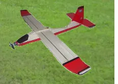
(Figure 1). These gadgets increase the precision of image acquisition conducted by UAV during flight mission.
Figure 1. An example of fixed-wing UAV
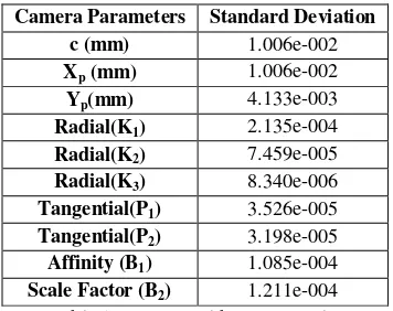
The photogrammetric products such as digital elevation model and digital orthophoto can be produced after a certain orientations through photogrammetric processes (Tahar and Ahmad, 2011; Tahar and Ahmad, 2012). The protogrammetric processes involve interior orientation, exterior orientation, aerial triangulation and bundle adjustment. Interior orientation requires information of camera calibration parameters such as focal length, principal distance (Xo, Yo), radial lens distortion (K1, K2, K3), tangential lens distortion (P1, P2) and affinity (B1) and scale factor (B2). Exterior orientation requires coordinates on the ground to define the image position was same during flight mission. Exterior orientation can be processed by using ground control points which are established by total station or global positioning system. In addition, inertial measurement unit is used to improve onboard GPS coordinates during flight mission. Inertial measurement unit (Mikropilot) was link with navigation control board and records all UAV position, altitude and rotates coordinates during flight mission. These parameters were saved automatically in GPS log file and were used during post processing during exterior orientation. This study introduce a new method for image registration in the image processing phase.
1.2 Study Area
This study was conducted in Gelang Patah in Johor, Malaysia, which is located within latitudes 1⁰ 26’N - 1⁰ 27’N and longitudes 103⁰ 34’E – 103⁰ 35’E. The map of the study area is shown in Figure 2. The landuse at the study area mainly includes urban area, forest, plantation oil palm and bare land.
Figure 2. Study area
2. DATA ACQUISITION
2.1 Flight Preparations
Data acquisition is solely obtained from unmanned aerial vehicle, with a specific fixed wing unit which autopilot system has been adopt from Mikropilot product. This UAV is equipped
with the current and advanced technologies such as onboard GPS, fiber optics gyro, autopilot chipset, electronic speed controller, wireless antenna, camera mount, high resolution digital camera, high end transmitter and inertial navigation system (Mikropilot). Figure 3 shows the digital camera that was installed at the bottom of UAV. The images were taken autonomously by UAV based on flight path which was programmed in a flight mission control software. Pre-flight planning is a must in photogrammetric work because it will reflect the quality of the end products. The coordinates were obtained from Google Earth Pro to identify the area of interest.
Figure 3. Digital camera
Generally, Google Earth inherited 20-50 meter accuracy (Potere, 2008) but it is still the fastest and the easiest way to get an idea of the study area, other alternative is to visit the study area and conduct survey observation. Next, the images of study area were cropped and saved in jpeg file. Raster image (jpeg file) needs to be registered by using ground control points to perform georeference processing. These processes can be done with well known geographical information system (GIS) software such as ArcGIS, ArcView or MapInfo software. There are at least three control points needed to perform georeference processed which can be obtained from google earth or GPS observation. Then, georeferenced images will be opened in lentsika flight planning software. Lentsika software is very effective for UAV flight planning because it includes coverage area, required resolution, number of images, attitudes, altitudes and flight path. After the user is satisfied with the flight planning of the study area, then it is saved in *.fly file. In the software, user needs to specify the area of interest and to determine each corner of the study. This software can generate flight path automatically based on user’s input. Finally, flight planning file from lentsika will be opened in ground control software known as Horizon software. Horizon software will finalize the flight pattern and altitude control. Normally, user is requested to enter ground resolution required for the mission. The software will automatically calculate the number of images taken, the number of waypoint, flight path and it will also calculate the exposure time. Flight planning file will be uploaded into autopilot chip or autonomous flight system in UAV via cable or wirelessly. In this study, we used 7 centimeter ground resolution at an altitude of 320 meter or 1200 feet.
After UAV has landed, GPS onboard should be switched off immediately, otherwise the GPS data will be lost. It is due to the limitation of GPS log file memory. The same been applied for the next flight mission. The operator is in charge of downloading all of the images from the digital camera and the GPS log file from the autopilot chip.
2.2 Camera calibration
Camera calibration was carried out to determine the parameter of the camera that is used for image acquisition. These parameters are required for interior orientation during image processing using photogrammetric software. In this study, self calibration bundle adjustment was carried out before flight mission. Plate calibration which has a dimension of about 0.6 meter x 0.6 meter and consist of 36 reflective target with various height were used in camera calibration. During the calibration processes, the camera captured eight images from different angle of view. This is known as the convergence method in photogrammetric work. The distance between camera and calibration plate is approximately the same. The images taken were processed in calibration software which is known as Australis software. Australis software requires the size of pixel, number of horizontal resolution and number of vertical horizontal of the images. Finally, this software will automatically produce parameters of the camera. Residual of bundle orientation after camera calibration reached sigma0 is 0.681µm. Root mean square (RMS) of image coordinate is about 0.27 µm. The result of the referring to the sigma0 values. The results obtained from camera the calibration were required in the interior orientation during image processing.
3. IMAGE PROCESSING
The UAVs images will be processed in photogrammetric software. In this study, Erdas Imagine was used to process all acquired images. All UAV images will be saved automatically in jpeg file and it will usually cover the whole coverage of the study area. Normally, photogrammetrist requires at least three or four ground control points for each model. Ground control points were established using GPS observation by either real time kinematic or rapid static method. However, the capablities of onboard GPS provide an opportunity for photogrammetrist to use the data for
Image registration is required for exterior orientation process in photogrammetric software. We propose a new image registration method that uses the onboard GPS as a primary control points for stitching of the UAV images. This registration was carried out to evaluate the initial position of photogrammetric product based on the onboard GPS .
The principal point (Fxo, Fyo) is the origin of image. The model. The fiducial points can be expressed by equations for F1(x) and F1(y) as shown in Equation 1 and 2.
F1(x) = Fxo + (Hp/2 - 2) Sp + ϵ (1) F1(y) = Fyo + (Vp/2- 2) Sp + ϵ (2)
Where Fxo and Fyo = origin coordinate of the image which is obtained from GPS onboard
Hp = number of horizontal pixel Vp = number of vertical pixel Sp = pixel size of image ϵ = rotation error
The Equation 1 and 2 are represented in matrix form.
F1(x)
F1(y)
= +− 2
− 2
( )
+(
ϵ
)
(3)The exposure location of an aerial photograph, an object point and its images on the image plane are all on a straight line. Therefore, collinearity condition equation must be applied in Equation 1 and 2 to eliminate rotation error (Paul and Bon, 2004). There are three rotations involved in this equation; omega (ω), phi (Φ), and kappa (κ) rotations. The rotation errors are the effect of air turbulence during flight mission due to the wind correction. The Equation 1 and 2 after rotation correction are shown in Equation 4 and 5.
Fxo, Fyo
F1
F2 F3
F1(x) = Xo + (Hp/2 2) Sp
-f ( )′ ( )′ ( )′
( )′ ( )′ ( )′
!
(4)F1(y) = Yo + (Vp/2 2) Sp
-f ( )′ ( )′ ( )′
( )′ ( )′ ( )′
!
(5)Where Fxo and Fyo= principal points of the image Hp = number of horizontal pixel
Vp = number of vertical pixel Sp = pixel size
f = camera focal length
m’s = function of the rotation angles omega, phi, kappa F1(x)’, F1(y)’, F1 (z)’ = rotate image coordinates are related to the measured photo coordinates F1(x) and F1(y).
Coordinate of F2, F3 and F4 can be derived by using Equations 1 - 5. The general formula can be defined in Equation 6 and 7.
Fn (x) = Fxo + (Hp/2 - 2) Sp + ϵ (6) Fn (y) = Fyo + (Vp/2- 2) Sp + ϵ (7)
Where Fn(x) and Fn(y) = position of diagonal coordinate x and y
In this study, all measured coordinates were used in the image processing for the production of digital orthophoto and digital elevation model. As mentioned in the data acquisition section, all acquired images will be processed by using photogrammetric software. In this study, for each photograph three control points were established; One control point was obtained from the principal point and the other two control points were measured from the proposed equations (Equation 6 and 7). These three control points were used to rectify each photograph and all rectified images were mosaiced to generate digital orthophoto of the study area. The result of digital orthophoto and digital elevation model is discussed in the result section.
3.2 Image processing based on Google Earth control points
The second method for image processing in this study used Google Earth coordinates as control points. Several control points were captured in Google Earth and were used for exterior orientation in the production of digital orthophoto and digital elevation model. The photogrammetric product can be computed
after going through certain photogrammetric steps such as interior orientation, exterior orientation, aerial triangulation and bundle adjustment. The results of image processing by using Google Earth coordinates and GPS onboard were compared and analyzed in the discussion section.
3.3 Data Verification
Photogrammetric products must be verified before they can be used for any applications. There were 57 checkpoints that were randomly distributed evenly for the whole study area. Each checkpoint was established by using Real Time Kinematic (RTK) GPS which required only 2-3 minutes per control point. The accuracy assessment of photogrammetric product in this study is discussed in the analysis section.
4. RESULTS
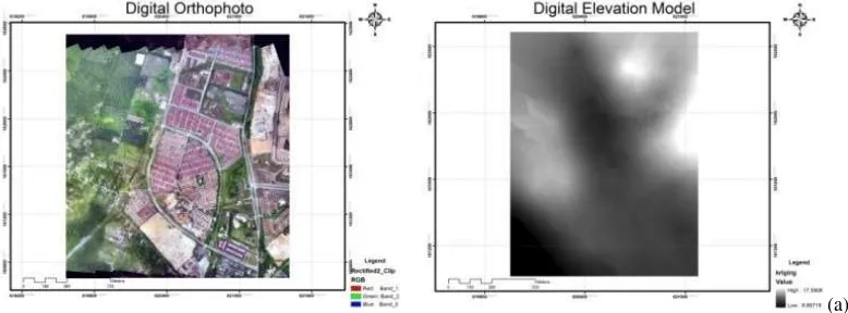
The result can be discussed in two cases; first case is the results of image processing by using proposed image registration algorithm and second case is the result of image processing by using control points from Google Earth coordinates. There were two photogrammetric products produced in this study, namely digital orthophoto and digital elevation model. The size of image block for this area is about two kilometer by two and half kilometer where 228 images were captured during flight mission. Spatial coverage of one image is about 326 meter x 245 meter. Each overlapped images were about 60 percent and sidelap were about 30 percent. These results were described in Figure 4(a) and Figure 4(b). Figure 4(a) shows the product of digital orthophoto after the rectification processes by using the proposed image registration method. The advantage of the proposed method is that the images can be rectified by using diagonal coordinate which was defined from the proposed algorithm and improve image matching during auto-tie point measurements. Rectified images were mosaiced and digital orthophoto was created for the study area. Figure 4(b) shows the product of digital orthophoto based on control points acquired from Google Earth coordinates.
Based on Figure 4, in graphical view, there is no difference between the digital orthophoto for both techniques while for the digital elevation model there were slight differences. This might be caused by inconsistency of Google Earth and onboard GPS coordinates used as control points in image processing. It is because coordinates obtained from Google Earth and onboard GPS has some error that need to be considered. However, the details on the accuracy of the assessment of both results are discussed in the dicussion section.
(b) Figure 4. (a) Digital Orthophoto and Digital Elevation Model for Proposed Algorithm; (b) Digital Orthophoto and Digital
Elevation Model for Google Earth Coordinates
(a)
(b)
Figure 5. (a) Linear graph X, Y, Z coordinates for GPS onboard; (b) Linear graph X, Y, Z coordinate for Google Earth (GE) coordinates.
Figure 5 shows that most of points fit in the line 1:1 (red line on the graph) for X coordinate and it can be concluded that x coordinates for GPS onboard are precise while x coordinates for Google Earth (GE) control points are less precise because some of the points are located higher and lower than line 1:1. Most of points are located exactly in line 1:1 for Y coordinate, thus it can be concluded that y coordinates for GPS onboard and GE control points are precise and reliable. The situation is different for Z coordinate because some of points are randomly located above and below line 1:1. However, there is a slight difference between GPS onboard and GE control points in which the result of GPS onboard showed better precision compared to GE control points. In contrast, proposed algorithm gives better precision compared to GE control points. However, the detail of points located on line 1:1 can be viewed if the linear graph is shown in a larger scale image size.
5. DISCUSSION
In this study, the accuracy of photogrammetric product was assessed based on root mean square error, mean absolute error and linear fit equation and determination of correlation coefficient for each result. The general formula of linear fit equation is illustrated in Equation 8.
y=a+bx (8)
Where a,b = coefficient data
superimposition between digital orthophoto and error distribution for GPS onboard and Google Earth respectively.
(a) (b)
Figure 6. Error Distribution; (a) GPS onboard; (b) Google Earth
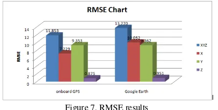
Based on Figure 6, most of the errors were distributed at the diagonal of digital orthophoto. It might be caused by interpolation of control points during image processing. The distribution error for x, and in this study, the accuracy of all photogrammetric products that were produced by using GPS onboard and GE control points were calculated by using root mean square error (RMSE). The accuracy was achieved based on digital orthophoto and digital elevation model from both methods. There were 57 checkpoints that were established randomly in the study area. RMSE for GPS onboard is +11.853 and RMSE for GE control points is +13.770 (Figure 7).
Figure 7. RMSE results
Based on Figure 7, the accuracy of GPS onboard gives a medium accuracy. Thus, it can be used for updating Google Earth image because satellite images from google earth gives error within +15m (Redzwan and Ramli, 2007).
6. CONCLUSION & FUTURE WORK
In conclusion, the proposed image registration method can improve image processing result with the condition that GPS onboard is stable during image acquisition. Furthermore, the difference of GPS onboard and GE control points is about +2meter. It can be concluded that GPS onboard has its limitation in x and y positioning which might be caused by GPS error. In future, calibration of GPS onboard will be carried out and the accuracy of GPS onboard will be assessed.
ACKNOWLEDGEMENT
Faculty of Architecture, Planning and Surveying Universiti Teknologi MARA (UiTM) and Faculty of Geoinformation & Real Estate, Universiti Teknologi Malaysia (UTM) are greatly acknowledged.
REFERENCES
David, G.S.III, and Benjamin, R.D., Charles, R., 2008. Development and Application of an Autonomous Unmanned Aerial Vehicle for Precise Aerobiological Sampling above Agricultural Fields. Journal of Field Robotics, 25 (3), pp. 133-147.
Dingus, B.R., Schmale, D.G., and Reinholtz, C.F., 2007. Development of an autonomous unmanned aerial vehicle for aerobiological sampling.
Phytopathology, 97(7), pp. 184.
Jwa, S. and Ozguner, U., 2007. Multi-UAV sensing over urban areas via layered data fusion. Statistical Signal Processing, SSP ’07. IEEE/SP 14th workshop on, pp. 576-580
Grenzdorffer, G.J., Engel, A., and Teichert, B., 2008. The Photogrammetric Potential of Low-Cost UAVs in Forestry and Agriculture. The international Archives of the Photogrammetry, Remote
Sensing and Spatial Information Sciences. Vol. XXXVII. Part B1.
Beijing, pp. 1207-1214
Herwitz, S.R., Johnson, L.F., Dunagan, S.E., Higgins, R.G., Sullivan, D.V., Zheng, J., Lobitz, B.M., Leung, J.G., Gallmeyer, B., Aoyagi, M., Slye, R.E. and Brass, J., 2004. Demonstration of UAV-based imaging for agricultural surveillance and decision support. Computer and Electronics in Agriculture, 44, pp.49-61
Osborne, J. and Rysdyk, R.,2005. Waypoint Guidance for Small UAVs in Wind. American Institute of Aeronautics and Astronautics University of Washington, Seattle, WA, 98115,USA.
Paul R.W. and Bon A.D., 2004. Elements of Photogrammetry with
application in GIS. International Edition. McGrawHill, pp. 551-554.
Potere, D., 2008. ,Horizontal Positional Accuracy of Google Earth’s High Resolution Imagery Archive Sensors 2008, 8, 7973-7981; DOI: 10.3390/s8127973
Redzwan, G., and Ramli, M.F.,2007. Geo-referencing the Satellite Image from Google Earth by Relative and Absolute Positioning. Malaysian
Journal of Science, 26 (2), pp. 135-141. ISSN 13943065
UVSIA, 2010. UAV Categories. Unmanned Vehicle Systems. International Association http://www.uav-info.com/uav-pdf/uav-categories.pdf (20 February 2011)
Tahar, K.N and Ahmad, A.,2011. Capability of Low Cost Digital Camera for Production of Orthophoto and Volume Determination. CSPA 2011 7th International Colloquium on Signal Processing & Its Applications IEEE. Penang, Malaysia, pp. 67-71.
Tahar, K.N., and Ahmad, A., 2012. A simulation study on the capabilities of rotor wing unmanned aerial vehicle in aerial terrain mapping.