OGC 09-127r2
Open Geospatial Consortium
Publication Date: 2012-01-25 Approval Date: 2011-12-13 External identifier of this OGC® document: http://www.opengis.net/spec/PUCK/v1.4/
Reference number of this OGC® project document: OGC 09-127r2 Version: 1.4 Category: OGC® Encoding Standard Editor: Tom O’Reilly
OGC
®PUCK Protocol Standard Version 1.4
Copyright notice
Copyright © 2012 Open Geospatial Consortium.
To obtain additional rights of use, visit http://www.opengeospatial.org/legal/.
Warning
This document is an OGC Member approved international standard. This document is available on a royalty free, non-discriminatory basis. Recipients of this document are invited to submit, with their comments, notification of any relevant patent rights of which they are aware and to provide supporting documentation.
Document type: OGC® Standard Document subtype: Encoding
OGC 09-127r2
Copyright © 2012 Open Geospatial Consortium.
Copyright © 2009, 2010, 2011, 2012 Monterey Bay Aquarium Research Institute
OGC 09-127r2
Copyright © 2012 Open Geospatial Consortium.
iii License Agreement
Permission is hereby granted by the Open Geospatial Consortium, ("Licensor"), free of charge and subject to the terms set forth below, to any person obtaining a copy of this Intellectual Property and any associated documentation, to deal in the Intellectual Property without restriction (except as set forth below), including without limitation the rights to implement, use, copy, modify, merge, publish, distribute, and/or sublicense copies of the Intellectual Property, and to permit persons to whom the Intellectual Property is furnished to do so, provided that all copyright notices on the intellectual property are retained intact and that each person to whom the Intellectual Property is furnished agrees to the terms of this Agreement.
If you modify the Intellectual Property, all copies of the modified Intellectual Property must include, in addition to the above copyright notice, a notice that the Intellectual Property includes modifications that have not been approved or adopted by LICENSOR.
THIS LICENSE IS A COPYRIGHT LICENSE ONLY, AND DOES NOT CONVEY ANY RIGHTS UNDER ANY PATENTS THAT MAY BE IN FORCE ANYWHERE IN THE WORLD.
THE INTELLECTUAL PROPERTY IS PROVIDED "AS IS", WITHOUT WARRANTY OF ANY KIND, EXPRESS OR IMPLIED, INCLUDING BUT NOT LIMITED TO THE WARRANTIES OF MERCHANTABILITY, FITNESS FOR A PARTICULAR PURPOSE, AND NONINFRINGEMENT OF THIRD PARTY RIGHTS. THE COPYRIGHT HOLDER OR HOLDERS INCLUDED IN THIS NOTICE DO NOT WARRANT THAT THE FUNCTIONS CONTAINED IN THE INTELLECTUAL PROPERTY WILL MEET YOUR REQUIREMENTS OR THAT THE OPERATION OF THE INTELLECTUAL PROPERTY WILL BE
UNINTERRUPTED OR ERROR FREE. ANY USE OF THE INTELLECTUAL PROPERTY SHALL BE MADE ENTIRELY AT THE USER’S OWN RISK. IN NO EVENT SHALL THE COPYRIGHT HOLDER OR ANY CONTRIBUTOR OF
INTELLECTUAL PROPERTY RIGHTS TO THE INTELLECTUAL PROPERTY BE LIABLE FOR ANY CLAIM, OR ANY DIRECT, SPECIAL, INDIRECT OR CONSEQUENTIAL DAMAGES, OR ANY DAMAGES WHATSOEVER RESULTING FROM ANY ALLEGED INFRINGEMENT OR ANY LOSS OF USE, DATA OR PROFITS, WHETHER IN AN ACTION OF CONTRACT, NEGLIGENCE OR UNDER ANY OTHER LEGAL THEORY, ARISING OUT OF OR IN CONNECTION WITH THE IMPLEMENTATION, USE, COMMERCIALIZATION OR PERFORMANCE OF THIS INTELLECTUAL PROPERTY.
This license is effective until terminated. You may terminate it at any time by destroying the Intellectual Property together with all copies in any form. The license will also terminate if you fail to comply with any term or condition of this Agreement. Except as provided in the following sentence, no such termination of this license shall require the termination of any third party end-user sublicense to the Intellectual Property which is in force as of the date of notice of such termination. In addition, should the Intellectual Property, or the operation of the Intellectual Property, infringe, or in LICENSOR’s sole opinion be likely to infringe, any patent, copyright, trademark or other right of a third party, you agree that LICENSOR, in its sole discretion, may terminate this license without any compensation or liability to you, your licensees or any other party. You agree upon termination of any kind to destroy or cause to be destroyed the Intellectual Property together with all copies in any form, whether held by you or by any third party.
Except as contained in this notice, the name of LICENSOR or of any other holder of a copyright in all or part of the Intellectual Property shall not be used in advertising or otherwise to promote the sale, use or other dealings in this Intellectual Property without prior written authorization of LICENSOR or such copyright holder. LICENSOR is and shall at all times be the sole entity that may authorize you or any third party to use certification marks, trademarks or other special designations to indicate compliance with any LICENSOR standards or specifications.
This Agreement is governed by the laws of the Commonwealth of Massachusetts. The application to this Agreement of the United Nations Convention on Contracts for the International Sale of Goods is hereby expressly excluded. In the event any provision of this Agreement shall be deemed unenforceable, void or invalid, such provision shall be modified so as to make it valid and enforceable, and as so modified the entire Agreement shall remain in full force and effect. No decision, action or inaction by LICENSOR shall be construed to be a waiver of any rights or remedies available to it.
OGC 09-127r2
OGC 09-127r2
Copyright © 2012 Open Geospatial Consortium.
v
8.2.6 PUCKSA – Set address referenced by the PUCK internal memory pointer ... 16
8.2.7 PUCKSZ – Get the size of PUCK memory ... 16
8.2.8 PUCKTY – Query PUCK type ... 16
8.2.9 PUCKVR – Get PUCK version string ... 17
8.2.10 PUCK – Null PUCK command ... 18
8.2.11 PUCKIM – Put PUCK device into instrument mode ... 18
8.2.12 PUCKVB – Verify baud rate support ... 18
8.2.13 PUCKSB – Set PUCK‐enabled instrument baud rate ... 19
8.2.14 PUCKIP – Get instrument port number ... 19
8.3 PUCK Error Codes ... 20
9 PUCK Instrument Datasheet ... 20
9.1 Instrument datasheet entries ... 21
9.1.1 Universally Unique Identifier ... 21
9.1.2 Version – Instrument datasheet version ... 21
9.1.3 Datasheet size – instrument datasheet size ... 22
9.1.4 Manufacture ID – Identifier of instrument manufacture ... 22
9.1.5 Manufacture Model – The model of a manufactures instrument ... 22
9.1.6 Manufacture Version – The version of a manufactures instrument model ... 22
9.1.7 Serial Number – Instrument serial number ... 23
9.1.8 Instrument Name – ASCII string containing instrument name ... 23
10 PUCK Payload ... 23
Table of Figures Figure 1: OGC SWE services, SensorML and PUCK ... xii
Figure 2: State diagram for RS232 PUCK ... 7
OGC 09-127r2
Copyright © 2012 Open Geospatial Consortium.
i.
Abstract
This standard defines a protocol for RS232 and Ethernet connected instruments. PUCK addresses installation and configuration challenges for sensors by defining a standard instrument protocol to store and automatically retrieve metadata and other information from the instrument device itself.
ii.
Keywords
ogcdoc, PUCK, plug-and-work, swe, sensors, instruments, oceans, firmware
iii.
Preface
This candidate standard has been submitted to the OGC by the Monterey Bay Aquarium Research Institute on behalf of the PUCK implementation community. PUCK has been used in conjunction with existing OGC Sensor Web standards.
iv.
Submitting organizations
The following organizations submitted this Implementation Standard to the Open Geospatial Consortium:
Monterey Bay Aquarium Research Institute (MBARI)
Universitat Politecnica de Catalunya, SARTI Research Group (UPC-SARTI)
Marine Institute of Memorial University of Newfoundland (MI)
Smart Ocean Sensors Consortium (SOSC)
OGC 09-127r2
Copyright © 2012 Open Geospatial Consortium.
vii 52north
University of California San Diego/Ocean Observatories Initiative
Northrop Grumman
Compusult Ltd
v.
Submission contact points
All questions regarding this document should be directed to the editor or the contributors:
Contact Affiliation Email
Tom O'Reilly (editor)
MBARI oreilly<at>mbari.org
Kent Headley MBARI headley<at>mbari.org
Duane R. Edgington
MBARI duane<at>mbari.org
Antoni Manuel Lazaro
UPC-SARTI antoni.manuel<at>upc.edu
Joaquin del Rio
Arne Broering 52 North broering<at>52north.org
Luis Bermudez SOSC lbermudez<at>opengeospatial.org
Robert Thomas Compusult Ltd rthomas<at>compusult.net
Scott Fairgrieve Northrop Grumman
Scott.Fairgrieve<at>ngc.com
Randy Gillespie MI Randy.Gillespie<at>mi.mun.ca
Christoph Waldmann
MARUM waldmann<at>marum.de
OGC 09-127r2
Copyright © 2012 Open Geospatial Consortium.
vi.
Revision history
Date Release Author Paragraph modified Description
2009-08-17 0.1.0 Carl Reed First version in OGC document template 2010-11-30 1.0 Tom O’Reilly Numerous Preparation for RFC
2010-12-30 1.0 Carl Reed Numerous Preparation for RFC
2011-06-02 1.0 Tom O'Reilly Numerous Preparation for RFC, completed requirements and conformance tests 2011-12-2 1.0 Carl Reed Numerous Prepare for publication as an OGC
standard
vii.
Changes to the OGC
®Abstract Specification
OGC 09-127r2
Copyright © 2012 Open Geospatial Consortium.
ix
Foreword
Attention is drawn to the possibility that some of the elements of this document may be the subject of patent rights. Open Geospatial Consortium shall not be held responsible for identifying any or all such patent rights. However, to date, no such rights have been claimed or identified.
Recipients of this document are requested to submit, with their comments, notification of any relevant patent claims or other intellectual property rights of which they may be aware that might be infringed by any implementation of the standard set forth in this document, and to provide supporting documentation.
Future Work
OGC PUCK protocol does not provide an authentication mechanism to write device contents. A user could write malicious metadata or even executable code to devices that implement PUCK payload. Likewise, malicious metadata could be written to devices that implement a writable datasheet. Subsequent readers of the datasheet or payload would then misidentify the instrument, misinterpret its data, or execute malicious code. This problem is not necessarily an issue for every PUCK deployment:
o Many sensor networks are protected by firewalls
o In almost all current PUCK implementations, the datasheet is "read only" o Some sensor networks will not expect and hence not execute code from
the PUCK payload
OGC 09-127r2
Copyright © 2012 Open Geospatial Consortium.
Introduction
Sensor networks consist of interconnected sensors as well as dedicated “hosts” or “peer” machines that control the sensors and process their data. One or more sensors are often physically integrated into a single “instrument” device. These components are connected through wired or wireless communication port interfaces; RS232 or Ethernet are
commonly used. Various interactions are possible on the network; a host machine may provide a user interface for an instrument, may acquire and log the instrument's data, or may distribute the data to a wider network.
In order to perform these functions, the host requires information about the instrument, including communication port configuration, knowledge of the instrument command protocol, and metadata that describe the instrument and the science data it produces. Many instruments do not themselves supply all of this information automatically, but instead require that the host be configured beforehand. Part of the configuration process generally involves installation of sensor-specific driver software on the host; the driver actually handles interaction with the instrument. In addition files that describe the sensor characteristics (“configuration files”) must be installed. Most sensor networks today require careful manual installation and configuration by technicians to assure that the software components are properly associated with the physical instruments that they represent. In some cases these manual steps must be performed in environments that are physiologically and psychologically challenging (e.g. in bad weather or aboard ship in rough seas), thus increasing the possibility of human procedural errors.
Standards such as OGC SWE and IEEE 1451 strive to integrate diverse instruments into networks with minimal human effort and high reliability. Nevertheless use of these standards may require several software components to be manually installed on the instrument network, including instrument "drivers", web servers, and metadata documents that describe instruments in a standard way.
PUCK protocol addresses these installation and configuration challenges by defining a standard instrument protocol to store and automatically retrieve metadata and other information from the instrument's "PUCK memory". This information can include descriptive documents such as OGC SWE SensorML or IEEE 1451 TEDS as well as actual instrument “driver” code. A host computer that understands PUCK can
automatically retrieve and utilize this information from the instrument itself when the device is installed. For example, a SensorML document and instrument driver code can be physically stored in the instrument's PUCK memory before deployment; the
OGC 09-127r2
Copyright © 2012 Open Geospatial Consortium.
xi interface.
PUCK defines a small standard “instrument datasheet” in PUCK memory that can be retrieved from any PUCK-enabled instrument. The datasheet metadata include a universally unique identifier (UUID) that is guaranteed to be unique among all PUCK-enabled instruments, as well as manufacturer and model codes. These metadata can serve as pointers to more extensive instrument information; e.g. instrument SensorML
documents could be stored in a separate network-accessible database that is keyed to instrument PUCK UUID. All compliant PUCK instruments must supply the datasheet. PUCK also defines an optional “PUCK payload” in PUCK memory that contains additional information needed to operate the instrument; this information can include instrument driver code and metadata such as SensorML. In the case of driver code, note that the code is not executed on the instrument itself; rather it is retrieved by a capable host machine through PUCK and executed on the host. PUCK does not restrict the payload content beyond standard payload "tags", leaving the content decision up to observatory developers and users.
PUCK augments but does not replace existing instrument protocols. Thus a manufacturer can modify its instrument firmware by adding PUCK commands to the already-existing instrument command set. This approach allows manufacturers to implement PUCK without abandoning their existing firmware and software applications. Since many instruments already include a non-volatile memory device (e.g. Flash), it is usually easy for manufacturers to allocate some of that memory to PUCK memory. Note that PUCK does not specify an instrument's "native protocol", i.e. the manufacturer-defined
commands that actually configure and operate the instrument. Instead it is expected that the native protocol can be deduced from references in the PUCK instrument datasheet or the optional PUCK payload.
Figure 1 illustrates how PUCK complements other OGC SWE standard components. SWE services must sometimes interact with an actual physical sensor in order to carry out client requests; e.g. the Sensor Planning Service Submit operation ultimately requires that data acquisition be triggered from a physical sensor. Many of today's sensors are not themselves network-capable; instead they are connected to the network through a sensor host machine's serial port. Moreover most sensors themselves do not implement a standard protocol; instead the SWE service must access the device through a sensor driver, which runs on the sensor host and translates the service request to the appropriate sensor protocol command. The driver may also transform the sensor's response to a standard format, e.g. it may transform the sensor's "raw" data to an OGC Observation and Measurement object. Moreover, the OGC services also need access to the sensor's
OGC 09-127r2
Copyright © 2012 Open Geospatial Consortium. Figure 1: OGC SWE services, SensorML and PUCK
The PUCK protcol was originally developed by the Monterey Bay Aquarium Research Institute (MBARI) to simplify the integration and maintenance of ocean sensor networks. MBARI first implemented the protocol in a small device that could be attached to the serial port of any existing RS232 instrument. This “external PUCK device” contains persistent storage for PUCK datasheet and payload, a small microprocessor that executes PUCK protocol, and a relay. When the device is in “PUCK mode”, incoming serial traffic from the host is relayed to the microprocessor, which processes PUCK commands. When switched to “Sensor mode” the relay connects the incoming serial lines to the attached instrument; thus the instrument itself processes incoming "native instrument" commands from the host. This prototype external PUCK device endowed any existing RS232
OGC 09-127r2
Copyright © 2012 Open Geospatial Consortium.
OpenGIS® Standard OGC 09-127r2
Copyright © 2012 Open Geospatial Consortium.
1
OGC Encoding standard: PUCK protocol
1 Scope
This standard defines OGC PUCK version 1.4 protocol for RS232 and Ethernet instruments. Every implementation of a PUCK v1.4 device shall adhere to this standard. PUCK is a member of the OGC SWE suite and can provide on-instrument storage for SensorML as well as driver code which implements SWE protocols. However PUCK may be used independently of the other SWE standards, e.g. non-SWE instrument descriptions such as IEEE 1451 TEDS may be stored in and
retrieved from a PUCK-enabled device. Annex B of this document describes several use-cases for PUCK.
1 Conformance
Conformance with this standrd shall be checked using all the relevant tests specified in Annex A (normative). The framework, concepts, and methodology for testing, and the criteria to be achieved to claim conformance are specified in ISO 19105:
Geographic information — Conformance and Testing.
In order to conform to this OGC™interface standard, a software implementation may choose to implement: Any one of the conformance levels specified in Annex A (normative).
2 Normative references
The following normative documents contain provisions that, through reference in this text, constitute provisions of this part of OGC standard. For dated references, subsequent amendments to, or revisions of, any of these publications do not apply.
IETF RFC 3927, "Dynamic Configuration of IPv4 Link-Local Addresses":
http://www.ietf.org/rfc/rfc3927.txt
IETF Draft Standard, "Multicast DNS": http://files.multicastdns.org/draft-cheshire-dnsext-multicastdns.txt
IETF Draft Standard, "DNS-based Service Discovery": http://files.dns-sd.org/draft-cheshire-dnsext-dns-sd.txt
IETF RFC 4122, "A Universally Unique Identifier (UUID) URN Namespace":
2 Copyright © 2012 Open Geospatial Consortium.
IETF RFC 793, "Transmission Control Protocol": http://www.ietf.org/rfc/rfc793.txt
Electronic Industries Association, "EIA Standard RS-232-C Interface Between Data Terminal Equipment and Data Communication Equipment Employing Serial Data Interchange", August 1969, reprinted in Telebyte Technology Data Communication Library, Greenlawn NY, 1985, no ISBN
3 Terms and definitions
For the purposes of this document, the following terms and definitions apply.
3.1 PUCK-enabled device, PUCK-enabled instrument
A device or instrument that implements PUCK protocol
3.2 RS232 PUCK
PUCK protocol for devices having an RS232 serial port over which the protocol is carried out.
3.3 IP PUCK
PUCK protocol for devices having an Ethernet port over which the protocol is carried out.
3.4 Host platform
A controller and required infrastructure capable of communicating with attached RS232 PUCK-enabled instruments.
3.5 Peer
A software component that utilizes IP PUCK to communicate with IP PUCK-enabled instruments over an IP network.
3.6 Instrument
A data-gathering device that may be composed of one or more sensors sharing a physical interface to a host or network
3.7 Metadata
Copyright © 2012 Open Geospatial Consortium.
3
3.8 Native commands, instrument mode, and instrument port
"Native commands" are instrument-specific manufacturer-defined commands that are not included in PUCK protocol. Native commands provide means to actually operate the instrument, including commands for configuration, sample acquisition, data retrieval, etc. "Instrument mode" refers to the state of a RS232 PUCK-enabled device in which native commands are recognized and processed. "Instrument port" refers to an IP PUCK-enabled instrument's TCP/IP port on which native commands are recognized and processed.
3.9 PUCK mode
The state of an RS232 PUCK-enabled device in which PUCK commands are recognized and processed. Response to native commands while in PUCK mode is not defined by this specification.
3.10 Plug and work
"Plug and work" refers to automated integration of an instrument into an observing system that occurs when the instrument is physically plugged into the system.
3.11 Smart Ocean Sensors Consortium
The Smart Ocean Sensors Consortium
(http://groups.google.com/group/sosclist/web/smart-ocean-sensors-consortium) consists of manufacturers and users dedicated to development of standard interfaces for marine instrumentation.
3.12 Instrument datasheet
A 96-byte data structure provided by every PUCK-enabled instrument; the instrument datasheet uniquely identifies and defines the device.
3.13 PUCK payload
Information can be stored in a device's optional "PUCK payload" memory; the payload content is not defined by the PUCK specification beyond standard payload "tags", but can be defined by individual observing systems.
3.14 External PUCK
4 Copyright © 2012 Open Geospatial Consortium. 3.15 Embedded PUCK
PUCK protocol embedded within an instrument’s firmware (contrast with external PUCK).
4 Document conventions
4.1 Typographical conventions
The following are conventions that are used through out this document.
PUCK input/output is displayed in the courier font, for example
GB<CR>
19200<CR>PUCKRDY<CR>
The notation <CR> and <LF> are used to denote carriage return and linefeed respectively
The notation [0,255] is used to denote a parameter range (e.g. 0 parameter 255)
Normative requirements are indicated in this document by the word REQ in bold font, followed by an identifying URI, e.g.
REQ /req/core/datasheet
Some requirements are declared within table cells, while others are prepended to clauses within the document text.
4.2 Symbols (and abbreviated terms)
Some frequently used abbreviated terms:
ISO International Organization for Standardization
OGC Open Geospatial Consortium
SOSC Smart Ocean Sensors Consortium
SWE Sensor Web Enablement
TEDS Transducer Electronic Data Sheet
UUID Universally Unique Identifier
Copyright © 2012 Open Geospatial Consortium.
5
4.3 Namespace convention
The URL http://www.opengis.net/spec/PUCK/v1.4/ is assumed throughout this document as the namespace prefix for PUCK requirement and conformance test URIs.
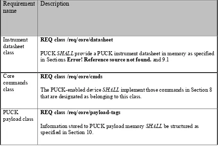
5 Core PUCK Requirements
Core PUCK requirements are applicable to all PUCK implementations (RS232 PUCK and IP PUCK).
Table 1: PUCK core requirement classes
Requirement
REQ class /req/core/datasheet
PUCK SHALL provide a PUCK instrument datasheet in memory as specified
in Sections Error! Reference source not found. and 9.1
Core commands class
REQ class /req/core/cmds
The PUCK-enabled device SHALL implement those commands in Section 8
that are designated as belonging to this class.
PUCK payload class
REQ class /req/core/payload-tags
Information stored to PUCK payload memory SHALL be structured as
specified in Section 10.
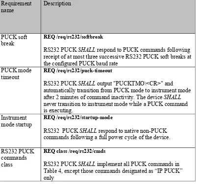
6 RS232 PUCK Requirements
6 Copyright © 2012 Open Geospatial Consortium. Table 2: RS232 PUCK requirements
Requirement
RS232 PUCK SHALL respond to PUCK commands following
receipt of at most three successive RS232 PUCK soft breaks at the configured PUCK baud rate
PUCK mode timeout
REQ /req/rs232/puck-timeout
RS232 PUCK SHALL output "PUCKTMO\<CR>" and
automatically transition from PUCK mode to instrument mode after 2 minutes of command inactivity. The device SHALL
never transition to instrument mode while a PUCK command is executing.
Instrument mode startup
REQ /req/rs232/startup-mode
RS232 PUCK SHALL respond to native non-PUCK commands following a full power cycle of the device.
RS232 PUCK commands class
REQ class /req/rs232/cmds
RS232 PUCK SHALL implement all PUCK commands in
Table 4, except those commands designated as “IP PUCK” only
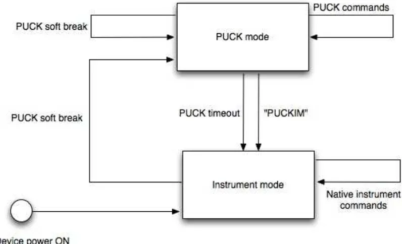
6.1 RS232 PUCK State Transitions
Figure 1 depicts states and state-transitions of an RS232 PUCK-enabled instrument, from the standpoint of a host.
Following retrieval of information from the PUCK-enabled instrument, the host may issue a command to put the device into instrument mode. When the device enters instrument mode the host platform may communicate with it using native instrument commands. An RS232 PUCK-enabled device can be switched from instrument mode to PUCK mode via the “PUCK soft break” mechanism.
Copyright © 2012 Open Geospatial Consortium.
7 Note that the definitions of instrument mode and PUCK mode (sections 1.2.5 and 1.2.6) allow implementations that respond to both PUCK and instrument-specific commands within a single mode, without violating any provisions of this specification.
Figure 2: State diagram for RS232 PUCK
6.2 RS232 PUCK Mode Timeout (Table 2, /req/rs232/puck-timeout)
If a PUCK-enabled device implementation distinguishes between instrument and PUCK modes, it SHALL automatically switch from PUCK mode to instrument mode following 2 minutes of inactivity, as measured from the completion of the last issued PUCK
command. Thus the device SHALL never transition to instrument mode while a PUCK command is executing. The device SHALL write the string “PUCKTMO<CR>” to its serial port when PUCK mode timeout occurs. Implementations that do not distinguish between PUCK mode and instrument mode need not implement PUCK timeout.
6.3 RS232 PUCK soft break (Table 2, /req/rs232/softbreak)
A host may switch a PUCK-enabled device from instrument mode to PUCK mode by issuing a PUCK soft break, which consists of the following sequence:
8 Copyright © 2012 Open Geospatial Consortium.
(wait 750 milliseconds)
“!!!!!!”
(wait 500 milliseconds)
(A soft break received by a device already in PUCK mode should be treated as a successful PUCK command, responding with "PUCKRDY".)
Note that a host may not necessarily “know” the baud rate for which the PUCK-enabled instrument's UART is configured. Thus the host may need to issue the soft break at several common baud rates before discovering the correct one. The host can confirm a successful soft break by sending the "null PUCK" command (“PUCK<cr>”) to the device; a response of PUCKRDY indicates that the device is now in PUCK mode. A compliant RS232 PUCK implementation SHALL switch to PUCK mode within three successive soft break attempts when those soft breaks are issued at the correct baud rate.
Note that the device SHALL not automatically switch its baud rate in response to a PUCK soft break.
7 IP PUCK Requirements
Copyright © 2012 Open Geospatial Consortium.
9
Table 3: IP PUCK requirements
Requirement
IP PUCK SHALL implement self-assigned IPv4 link-local addresses per IETF RFC 3927
(http://www.ietf.org/rfc/rfc3927.txt) Multicast
DNS
REQ /req/ip/multi-dns
IP PUCK SHALL implement multicast DNS for automatic name assignment, per http://files.multicastdns.org/draft-cheshire-dnsext-multicastdns.txt
DNS service discovery
REQ /req/ip/discovery
IP PUCK SHALL implement DNS Service Discovery
(DNS-SD) protocol, as defined at http://files.dns-sd.org/draft-cheshire-dnsext-dns-sd.txt, with service type "_puck._tcp".
PUCK port REQ /req/ip/puck-port
All PUCK commands and responses SHALL be carried out on a designated PUCK port; this port SHALL be specified in the DNS-SD SRV record.
TCP protocol REQ /req/ip/tcp
All communications on the PUCK port SHALL be implemented with connection-oriented TCP protocol as defined at http://www.ietf.org/rfc/rfc793.txt
Exclusive PUCK port access
REQ /req/ip/exclusive-access
10 Copyright © 2012 Open Geospatial Consortium.
PUCK port access timeout
REQ /req/ip/access-timeout
A peer connection to the PUCK port SHALL timeout after two minutes of inactivity since completion of the last PUCK command, at which time the IP PUCK will write the string “PUCKTMO<CR>” to the PUCK port and close the connection to the peer.
IP PUCK commands class
REQ /req/ip/cmds class
An IP PUCK instrument SHALL implement all PUCK commands in Table 4, except those commands designated as “RS232 only”
The PUCK port is used for PUCK commands, and the instrument SHALL also provide a port for native instrument protocol (see Table 3, /req/ip/puck-port). The RS232 PUCK concepts of “PUCK mode” and “instrument mode” are not applicable to IP PUCK.
7.1 Zeroconf implementation
Every IP PUCK-enabled instrument SHALL implement Zeroconf DNS Service Discovery (DNS-SD) protocol, as defined at http://files.dns-sd.org/draft-cheshire-dnsext-dns-sd.txt
(Table 3, /req/ip/discovery).
The IP PUCK service type SHALL be specified “_puck._tcp”.
The instrument response to SRV requests SHALL specify port number as the PUCK port number (Table 3, /req/ip/puck-port).
The instrument should respond to PTR requests with a suitably mnemonic instance name. For example, instance name could be “BrandX-modelY-1234”, denoting manufacturer, model, and serial number. Note that instance names can have a length of up to 63 bytes, and may contain Unicode or ASCII characters including space, punctuation, numbers, upper and lower case, and punctuation.
Copyright © 2012 Open Geospatial Consortium.
11
8 PUCK commands
PUCK defines a simple command-response protocol. PUCK commands are interpreted by an RS232 instrument in PUCK mode, or by an IP instrument when received on the PUCK port. PUCK commands are expressed as ASCII strings, beginning with “PUCK” and are terminated by a <CR>. All PUCK commands are case-sensitive, and are in uppercase. When a command is issued the device will attempt to execute that command. Upon successful execution the PUCK-enabled device will return the characters:
PUCKRDY<CR>
This indicates that the PUCK-enabled instrument is ready for the next command. The string “PUCK<CR>” is also a valid command (the “null command”) that results in a PUCKRDY response. If the PUCK-enabled instrument is unable to execute a command beginning with the characters “PUCK” successfully it will issue the characters
ERR ####<CR>
PUCKRDY<CR>
Where the ‘####’ is a four digit base ten error code in the range [1,9999]. PUCK error codes are defined in Table 6. If the command is a request for information then the command will return the information requested followed by the characters
PUCKRDY<CR>
The PUCK-enabled instrument will terminate any transaction initiated by a PUCK command with the characters
PUCKRDY<CR>
at which point it is ready for another command to be issued.
8.1 PUCK memory
Every compliant PUCK-enabled instrument must allocate a section of non-volatile "PUCK memory". PUCK memory contains the PUCK datasheet and (optionally) PUCK payload. PUCK memory is addressed starting at 0; the highest PUCK memory address is determined by the result of the PUCKSZ command. The "PUCK memory pointer" refers to the PUCK memory address that will be read or written by the next PUCKRM or PUCKWM command. The pointer can be set with the PUCKSA command, and its current value can be read with the PUCKGA command.
12 Copyright © 2012 Open Geospatial Consortium.
defined as the following sequence of commands, with no other commands intervening:
1. The PUCKEM command to erase all of PUCK memory 2. Optionally a PUCKSA command to set the starting address
3. One or more PUCKWM commands to write to PUCK-enabled instrument memory 4. The PUCKFM command to flush PUCK memory contents to non-volatile storage
Note that the PUCKFM (flush PUCK memory) command should be used only after a write session is complete; i.e. after PUCKFM is issued, no more PUCKWM commands are allowed until a new write session is initiated with PUCKEM.
8.2 PUCK Command specifications
Table 4 is a summary of all PUCK commands. In the case of RS232 PUCK, the
Copyright © 2012 Open Geospatial Consortium.
13
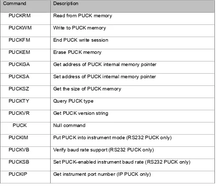
Table 4: PUCK command summary
Command Description
PUCKRM Read from PUCK memory
PUCKWM Write to PUCK memory
PUCKFM End PUCK write session
PUCKEM Erase PUCK memory
PUCKGA Get address of PUCK internal memory pointer
PUCKSA Set address of PUCK internal memory pointer
PUCKSZ Get the size of PUCK memory
PUCKTY Query PUCK type
PUCKVR Get PUCK version string
PUCK Null command
PUCKIM Put PUCK into instrument mode (RS232 PUCK only)
PUCKVB Verify baud rate support (RS232 PUCK only)
PUCKSB Set PUCK-enabled instrument baud rate (RS232 PUCK only)
PUCKIP Get instrument port number (IP PUCK only)
The following subsections discuss each command in detail. Note that for each command there is an associated “timeout” specification. Timeout is defined as the time between transmission of the command’s terminating carriage return and receipt of the first byte of the device response message. Commands designated “RS232 PUCK only” should not be recognized by IP PUCK implementations. Commands designated “IP PUCK only” should not be recognized by RS232 PUCK implementations.
8.2.1 PUCKRM – Read from PUCK memory
14 Copyright © 2012 Open Geospatial Consortium.
bytes requested has been sent. When the final byte has been sent, the PUCK-enabled instrument SHALL append the byte packet with the ASCII character ‘]’ and the PUCKRDY<CR> terminator.
Errors
ERR 0020 – the number of bytes requested is out of range.
Timeout: 500 milliseconds
Example
PUCK RX: PUCKRM 10<CR>
PUCK TX: [0123456789]PUCKRDY<CR>
8.2.2 PUCKWM – Write to PUCK memory
REQ /req/core/cmds/puckwm: The PUCKWM command writes bytes to PUCK memory. The command SHALL accept an ASCII parameter from 0 to 32 specifying the number of bytes to be written to PUCK memory, expressed in decimal format. After the PUCKWM command and parameter have been entered the PUCK-enabled instrument
SHALL accept the number of binary bytes requested for storage to PUCK memory. The bytes SHALL be stored starting at the address pointed to by the memory pointer (see commands PUCKSA and PUCKGA for memory pointer details). The memory pointer
SHALL be incremented appropriately for each successful PUCKWM command executed by the PUCK-enabled instrument. If the number bytes requested to write exceeds PUCK memory capacity based on the current address of the memory pointer then an ERR 0021
SHALL be returned. If the PUCK-enabled instrument attempts to write to a read-only region of memory an ERR 0022 SHALL be returned (see section 9 for a description of the read-only instrument datasheet option). If a write is attempted before PUCK memory has been initialized by the PUCKEM command, an ERR 0023 is returned.
Errors
ERR 0020 – the number of bytes to be written is out of range.
ERR 0021 – address requested out of range.
ERR 0022 – write attempted to read only memory.
ERR 0023 – write attempted to non-initialized memory
Timeout: 500 milliseconds
Example
PUCK RX: PUCKWM 10<CR>0123456789
Copyright © 2012 Open Geospatial Consortium.
15
8.2.3 PUCKFM – Flush to persistent memory
REQ /req/core/cmds/puckfm: The PUCKFM command ensures that any bytes buffered by the PUCK-enabled instrument during a write session (section 8.1) are stored to PUCK memory immediately, terminating the write session. Following a PUCKFM command, no other PUCKWM commands should be attempted until a new write session is initiated
with PUCKEM. A PUCK implementation SHALL accept the PUCKFM command
whether or not the particular PUCK implementation requires it.
Errors
Timeout: 30 seconds
Example
PUCK RX: PUCKFM<CR>
PUCK TX: PUCKRDY<CR>
8.2.4 PUCKEM – Erase PUCK memory
REQ /req/core/cmds/puckem: The PUCKEM command is used to erase all of PUCK memory with the exception of the datasheet if it is read-only. The command SHALL put the memory in a state such that the PUCKWM command can be used to store bytes to PUCK memory. Any write sessions to the PUCK-enabled instrument should be proceeded by the PUCKEM command (section 8.1). After the execution of the PUCKEM command the address held by the PUCK memory pointer SHALL be 0.
Errors
Timeout: 30 seconds
Example
PUCK RX: PUCKEM<CR>
PUCK TX: PUCKRDY<CR>
8.2.5 PUCKGA – Get address referenced by PUCK internal memory pointer
REQ /req/core/cmds/puckga: The PUCKGA command is used to return the memory address (expressed in decimal) pointed to by the PUCK memory pointer. When the PUCKRM or PUCKWM command are used the PUCK-enabled instrument reads or writes bytes starting at the address pointed to by the memory pointer. For every byte that is read or written to PUCK memory, the memory pointer will be incremented by 1.
Errors
16 Copyright © 2012 Open Geospatial Consortium.
Example
PUCK RX: PUCKGA<CR>
PUCK TX: 1234<CR>PUCKRDY<CR>
8.2.6 PUCKSA – Set address referenced by the PUCK internal memory pointer
REQ /req/core/cmds/pucksa: The PUCKSA command sets the PUCK memory address value of the PUCK memory pointer. When the PUCKRM or PUCKWM command are used the PUCK-enabled instrument reads or writes bytes starting at the address pointed to by the memory pointer. For every byte that is read or written to PUCK memory, the memory pointer will be incremented by 1. If an attempt is made to set the memory pointer to an address outside of PUCK memory range the PUCK SHALL indicate that an address range violation has occurred by returning error 0021. The specified address is expressed in decimal format.
Errors
ERR 0021 – memory address out of range
Example
PUCK RX: PUCKSA 1234<CR>
PUCK TX: PUCKRDY<CR>
8.2.7 PUCKSZ – Get the size of PUCK memory
REQ /req/core/cmds/pucksz: The PUCKSZ command is used to determine the total number of bytes that may be stored in PUCK memory, including PUCK instrument datasheet and payload. PUCKSZ returns the total (used and unused) number of bytes expressed in decimal format.
Errors
Timeout: 500 milliseconds
Example
PUCK RX: PUCKSZ<CR>
PUCK TX: 1048576<CR>PUCKRDY<CR>
8.2.8 PUCKTY – Query PUCK type
Copyright © 2012 Open Geospatial Consortium.
17
Table 5: PUCK type flags
PUCK Attribute Description
000 Embedded PUCK, read-write datasheet
0001 Embedded PUCK, read-only datasheet memory
0002 PUCK hardware is external to the instrument
0003 – 8000 Reserved
Errors
Timeout: 500 milliseconds
Example
PUCK RX: PUCKTY<CR>
PUCK TX: 0003<CR>PUCKRDY<CR>
8.2.9 PUCKVR – Get PUCK version string
REQ /req/core/cmds/puckvr: The PUCKVR command is used to request a version identifier of the PUCK implementation. When the PUCKVR command is issued the PUCK SHALL return a version string having the following format:
vx.y
where the literal lowercase “v” is followed by “major version number” x, followed by literal ‘.’, followed by the “minor version number” y. There are no spaces in the version string. The values of x and y are determined by the version of PUCK which has been implemented.
Errors
Timeout: 500 milliseconds
Example
PUCK RX: PUCKVR<CR>
18 Copyright © 2012 Open Geospatial Consortium. 8.2.10 PUCK – Null PUCK command
REQ /req/core/cmds/null-puck: The PUCK command simply results in a PUCKRDY response from the device if it is in PUCK mode (RS232 PUCK) or if received on the PUCK port (IP PUCK).
Errors
Timeout: 100 milliseconds
Example
PUCK RX: PUCK<CR>
PUCK TX: PUCKRDY<CR>
8.2.11 PUCKIM – Put PUCK device into instrument mode
REQ /req/rs232/cmds/puckim: Upon receiving PUCKIM, an RS232 PUCK-enabled instrument SHALL recognize and process subsequent native instrument commands. PUCKIM applies to RS232 PUCK only.
Errors
Timeout: 500 milliseconds
Example
PUCK RX: PUCKIM<CR>
PUCK TX: (undefined)
8.2.12 PUCKVB – Verify baud rate support
REQ /req/rs232/cmds/puckvb: The PUCKVB command is used to verify that a PUCK implementation supports a particular baud rate. The VB command followed by an ASCII representation of a baud rate SHALL cause the PUCK implementation to return
YES<CR> or NO<CR> followed by the PUCKRDY<CR> prompt. PUCKVB applies to RS232 PUCK only.
Errors
Timeout: 500 milliseconds
Example
PUCK RX: PUCKVB 9600<CR>
Copyright © 2012 Open Geospatial Consortium.
19
PUCK RX: PUCKVB 1234<CR>
PUCK TX: NO<CR>PUCKRDY<CR>
8.2.13 PUCKSB – Set PUCK-enabled instrument baud rate
REQ /req/rs232/cmds/pucksb: The PUCKSB command is used to change the RS232 PUCK baud rate. The PUCKSB command followed by an ASCII representation of a valid baud rate SHALL cause the PUCK-enabled instrument to set its UART to the requested baud rate. The PUCK implementation SHALL return the PUCKRDY<CR> prompt at the newly requested baud rate if successful. If the requested baud rate is not available then the PUCK implementation SHALL return an error code indicating that the requested baud rate is invalid for this implementation of RS232 PUCK. The host can determine if a particular baud rate is valid by using the PUCKVB command. PUCKSB applies to RS232 PUCK only.
Errors
Timeout: 500 milliseconds
ERR 0010 – Invalid baud rate requested
Example
PUCK RX: PUCKSB 19200<CR>
PUCK TX: PUCKRDY<CR>
8.2.14 PUCKIP – Get instrument port number
REQ /req/ip/cmds/puckip: The PUCKIP command returns an IP port number that is used for native instrument commands. The port is expressed as a decimal number followed by a carriage return, followed by the PUCKRDY<CR> prompt. PUCKIP applies to IP PUCK only.
Example
PUCK RX: PUCKIP<CR>
20 Copyright © 2012 Open Geospatial Consortium. 8.3 PUCK Error Codes
Table 6: PUCK error codes
Error Code Description
0004 No command match
0010 Invalid baud rate requested
0020 Bytes requested for read or write out of range
0021 Address requested out of range
0022 Write attempted to read only memory
0023 Write attempted to non-initialized memory
9 PUCK Instrument Datasheet
REQ /req/core/datasheet/map: The PUCK instrument datasheet SHALL occupy the first contiguous 96 bytes of PUCK memory. Fields within the datasheet SHALL be ordered as shown in Table 7, e.g. the UUID is located at address 0. The instrument datasheet may optionally be only. In the case of embedded PUCK, it is desirable to have a read-only instrument datasheet, as the information should never change for the life of the instrument. It can be determined whether an instrument datasheet is read-only via the PUCKTY command. The formats shown in the "Format" column of Table 7 are as follows:
U32 – an unsigned 32-bit integer stored in big endian format
U16 – an unsigned 16-bit integer stored in big endian format
UUID – the Leach-Salz variant of a universally unique identifier
Copyright © 2012 Open Geospatial Consortium.
21
Table 7: Instrument datasheet memory map
Description Size (bytes) Format
UUID for instrument 16 UUID
Version of instrument datasheet 2 U16
Datasheet size 2 U16
Manufacture ID 4 U32
Manufacture model 2 U16
Manufacture version 2 U16
Serial number 4 U32
Instrument name 64 CHAR ARRAY
Total size 96
9.1 Instrument datasheet entries 9.1.1 Universally Unique Identifier
REQ /req/core/datasheet/uuid: The UUID SHALL be a Leach-Salz variant of a universally unique identifier assigned to the instrument that is associated with this PUCK-enabled instrument. The UUID uniquely identifies a specific instance of an instrument; thus two different instruments having identical manufacturer, model, and version codes must have different UUIDs. A description of the Leach-Salz UUID
generation algorithm is described by IETF RFC 4122 at http://www.ietf.org /rfc4122.txt.
9.1.2 Version – Instrument datasheet version
22 Copyright © 2012 Open Geospatial Consortium. Table 8: Instrument datasheet versions
Instrument datasheet version Specification revision
1 MBARI PUCK Specification revision 1.2
2 MBARI PUCK Specification revision 1.3
3 OGC PUCK Specification revision 1.4
9.1.3 Datasheet size – instrument datasheet size
REQ /req/core/datasheet/size: The datasheet size entry SHALL be a U16 number specifying the size in bytes of the instrument datasheet, expressed in decimal format. For PUCK version 1.4, this number SHALL be equal to 96.
9.1.4 Manufacture ID – Identifier of instrument manufacture
The manufacture identifier should be a U32 number that is assigned by the Smart Ocean Sensors Consortium.
Table 9: Manufacturer ID numbers
Manufacture ID Description
0 No manufacture ID assigned
1 – 255 Experimental use
256 – 4,294,967,295 Managed by Smart Ocean Sensors Consortium
9.1.5 Manufacture Model – The model of a manufactures instrument
The manufacture model is a U16 that should be used by the manufacture to identify different instrument models. A value of 0 means that no model has been assigned to this instrument. All assigned model numbers should be made available by the instrument manufacturer for use by PUCK application developers.
9.1.6 Manufacture Version – The version of a manufactures instrument model
Copyright © 2012 Open Geospatial Consortium.
23
9.1.7 Serial Number – Instrument serial number
The serial number is a U32 number that should be assigned by manufactures. The serial number should be set to 0 if it is not available.
9.1.8 Instrument Name – ASCII string containing instrument name
The instrument name is a free-form ASCII string containing the name of the instrument. Any unused characters should be set to 0. If the instrument name is not used all
characters should be set to 0.
10 PUCK Payload
This section describes the structure of information stored in the optional PUCK payload memory.
Allocation of PUCK payload memory is optional for manufacturers. Payload capacity can be determined by the PUCKSZ command, minus the datasheet size (the third item in Table 7), and may be equal to zero. Note that payload content is not constrained in any way by the PUCK commands in Table 4. However this section of the PUCK standard defines structure and format that should be imposed by applications that write to PUCK payload memory.
PUCK payload memory can contain one or more logical payload components
simultaneously, limited only by payload capacity. PUCK does not restrict the format or content of individual components, which may be human-readable text, binary format information, or a combination of these.
REQ /req/core/payload/tags: Applications that write to PUCK payload memory SHALL
divide the payload content into one or more logical payload component; each logical PUCK payload component SHALL be immediately preceded in payload memory by a valid XML empty element tag consisting of ASCII bytes, which SHALL follow the following format:
<puck_payload type=”type” name=”name” size=”size” md5=”checksum” next_addr=”address” version=”version” />
The payload component’s content SHALL immediately follow the tag’s “/>” closure characters. The tag name (puck_payload) and the attribute names are case sensitive; all attributes (except version) are required and attribute values must be enclosed in quotes.
24 Copyright © 2012 Open Geospatial Consortium. Table 10: Payload component tag components
Attribute Name Required Description
type Y Indicates payload type. Table 11 shows
standard types
name Y Payload name. Payload may be stored in a file
of this name when extracted.
size Y Payload size in bytes, not including the tag
itself
md5 Y MD5 checksum of the payload (not including
the tag)
next_addr Y PUCK memory address of the next payload
tag; -1 indicates no more payloads
version N
Optional version information allowing host systems to accommodate one or more variations of a type
Thus the tags specify a linked list of components in PUCK payload memory. The components need not be contiguous, i.e. it is allowed to have unused memory between components. Figure 3 shows a schematic map of PUCK memory.
Table 11 is a list of standard PUCK payload component types.
Copyright © 2012 Open Geospatial Consortium.
25
Table 11: Standard payload component type names
Payload Type Description
IEEE-1451-binary-TEDS IEEE-1451 TEDS (binary format)
IEEE-1451-xml-TEDS IEEE-1451 TEDS (XML format)
SWE-SensorML SensorML format
MBARI-SIAM MBARI SIAM JAR file
26 Copyright © 2012 Open Geospatial Consortium.
Annex A: Recommended Conformance Tests
Core PUCK Tests
This section describes compliance tests that are common to both RS232 and IP PUCK implementations. If testing an RS232 PUCK-enabled instrument, these tests presume that the test software issues PUCK commands after putting the instrument into PUCK mode via PUCK soft break. If testing an IP PUCK-enabled instrument, the tests presume that test software issues PUCK commands via connection to the PUCK port.
a. PUCK memory integrity test
/conf/core/memory-integrity-test
Requirements addressed: /req/core/cmds/pucksz, /req/core/cmds/puckem, /req/core/cmds/pucksa, /req/core/cmds/puckwm, /req/core/cmds/puckfm, /req/core/cmds/puckga, /req/core/cmds/puckrm
Issue PUCKSZ command to determine total PUCK memory – verify that returned value matches device specification.
Determine whether datasheet is read-write or read-only (with PUCKTY command); if read-only, subtract datasheet size (96 bytes for PUCK v1.4) from PUCKSZ result to get total writable payload size.
The following procedure should be followed for both "walking-1's" and "walking-0's" tests:
Issue PUCKEM to erase memory and begin PUCK write session. Issue PUCKSA 0 (read-write datasheet) or PUCKSA 96 (read-only
datasheet) to set starting address.
Repeat until all of PUCK memory has been written:
Issue PUCKWM to fill PUCK memory block with walking-1's or walking-0's pattern.
Issue PUCKSA to set memory pointer to next PUCK memory block
Issue PUCKFM to flush, close PUCK write session.
Issue PUCKSA and PUCKRM commands to read memory, compare to expected walking-1's or walking-0's pattern
b. PUCK memory pointer test
Copyright © 2012 Open Geospatial Consortium.
27 Requirements addressed: /req/core/cmds/puckty, /req/core/cmds/puckvr,
/req/core/cmds/pucksa, /req/core/cmds/pucksz, /req/core/cmds/puckga
Issue PUCKTY; verify that PUCK is of expected type Issue PUCKVR; verify expected version (e.g. “v1.4”)
Issue invalid PUCK command “PUCKFOOBAR”; verify “ERR 0004” return
Issue “PUCKSA 0” to set memory pointer to start of PUCK memory; issue “PUCKGA” and verify it returns “0”. Get size of PUCK memory with “PUCKSZ”, issue “PUCKSA s-1” (where “s” is result of PUCKSZ), verify that “PUCKGA” returns s-1. Issue “PUCKSA s” to set memory pointer to location beyond valid PUCK memory, verify that it returns “ERR 0021”
c. PUCK datasheet test
/conf/core/datasheet
Requirements addressed: /req/core/datasheet/map, /req/core/datasheet/uuid, /req/core/datasheet/version, /req/core/datasheet/size
Step 1: Generate a datasheet and write to PUCK memory with the "PUCKWM" command. When generating the datasheet fields note that the values for "datasheet
version" is constrained to 3, and "datasheet version" is constrained to 96. The UUID must be generated using the Leach-Salz algorithm described at http://www.ietf.org/rfc/rfc4122.txt. "Manufacturer ID", "Manufacturer model", "Manufacturer version", and "Serial number" should be set per the directions in Section 9.1 of this specification.
Step 2: After writing the datasheet, issue "PUCKRM 96\r" and examine the resulting 96 bytes, making reference to the PUCK datasheet memory map in Table 7. Verify that "datasheet version" is equal to 3. Verify that "datasheet size" is equal to 96. Verify that remaining field values are as generated in step 1 of this test.
d. PUCK payload test
/conf/core/puck-payload-test
Requirements addressed: /req/core/payload/tags, /req/core/payload/swe-tag
Note that the standard PUCK payload tag rules are NOT enforced by firmware within the PUCK-enabled device itself. Rather, they must be implemented by any application that writes to PUCK payload.
RS-232 PUCK Tests
This section describes compliance tests that are specific to RS232 PUCK
28 Copyright © 2012 Open Geospatial Consortium.
commonly-used set. In this document, we define “common baud rates” to include 1200, 2400, 4800, 9600, 19200, and 38400.
a. PUCK softbreak test
/conf/rs232/puck-softbreak-test
Requirements addressed: /req/rs232/softbreak, /req/rs232/cmds/puckim, /req/core/cmds/null-puck
Ensure that device is in “instrument mode” with PUCKIM command. Note that we don’t necessarily know a priori instrument’s baud when trying to assert PUCK mode; thus the PUCK softbreak should be issued at all common baud rates until a “PUCKRDY” response is received in response to the null PUCK command ("PUCK\r").
At each common baud rate, issue the following sequence:
Issue “@@@@@@” (wait 750 milliseconds) Issue “!!!!!!”
(wait 500 milliseconds)
Issue “PUCK\r”; check for “PUCKRDY” response (indicates success)
Verify that the device responds to "PUCK\r" with "PUCKRDY" within three successive soft break attempts at the correct baud rate.
PUCK mode timeout test /conf/rs232/puck-timeout-test
Requirements addressed: /req/rs232/softbreak, /req/core/cmds/null-puck, /req/rs232/puck-timeout
Issue PUCK soft break to put instrument into PUCK mode, verify with “PUCK\r” which should return “PUCKRDY”. Issue no further commands, and verify that “PUCKTMO\r” is received from instrument 120 seconds later. Verify that instrument now recognizes non-PUCK "native" instrument commands.
e. Instrument mode test
/conf/rs232/instrument-mode-test
Requirements addressed: /req/rs232/startup-mode, /req/rs232/softbreak, /req/core/cmds/null-puck, /req/rs232/cmds/puckim
Issue PUCK soft break to put instrument into PUCK mode, verify with “PUCK\r” which should return “PUCKRDY”. Then issue “PUCKIM” command, and verify that
Copyright © 2012 Open Geospatial Consortium.
29 Remove all power from instrument, wait 10 seconds, then reapply power. Verify that instrument recognizes and processes non-PUCK "native" instrument commands.
f. Valid PUCK baudrates test
/conf/rs232/valid-baudrates-test
Requirements addressed: /req/rs232/cmds/puckvb, /req/rs232/cmds/pucksb, /req/rs232/softbreak, /req/core/cmds/null-puck
Issue PUCK soft break at common bauds to establish connection with instrument in PUCK mode.
For each common baud rate:
Issue “PUCKVB b\r”, where ‘b’ is the baud rate. If PUCK responds “YES”, note ‘b’ as a valid PUCK baud
For each valid PUCK baud as determined above: Issue “PUCKSB b\r” to set PUCK baud rate to ‘b’
Set host port’s baud to ‘b’, issue “PUCK\r” and verify “PUCKRDY” response
IP PUCK Tests
This section describes compliance tests that are specific to IP PUCK implementations.
g. ZeroConf compliance test
/conf/ip/zeroconf-test
Requirements addressed: /req/ip/address, /req/ip/multi-dns, /req/ip/discovery, /req/ip/puck-port, /req/ip/tcp
For this test, run a ZeroConf browser (e.g. Bonjour Browser) on the instrument test network.
Power up instrument, then connect to IP network via Ethernet connection. Using
ZeroConf browser, verify that instrument PUCK service appears on network with service type "_puck._tcp", with a link-local address, and that instrument has human-readable name.
Verify that PUCK commands are recognized on a TCP connection established on the PUCK port (specified by the DNS SRV request response).
h. Exclusive PUCK port access test
/conf/ip/puck-port-test
30 Copyright © 2012 Open Geospatial Consortium.
While one peer has a TCP connection to the PUCK port, run a second peer that attempts to connect; the second peer should receive TCP/IP error 10061 (connection refused).
i. PUCK port timeout test
/conf/ip/puck-port-timeout-test
Requirements addressed: /req/ip/access-timeout, /req/core/startup
Power-cycle PUCK-enabled device, wait 4 seconds then attempt to establish connection to PUCK port, issue “PUCK\r”, verify “PUCKRDY” response; verify that connection establishment and processing of commands on PUCK port is achieved within 5 seconds of device power-up. Do not issue further commands on PUCK port, and verify receipt of “PUCKTMO” from port after 120 seconds followed by disconnection. Verify that peer can immediately reconnect to PUCK port.
j. Native instrument port test
/conf/ip/native-port-test
Requirements addressed: /req/ip/cmds/puckip
Copyright © 2012 Open Geospatial Consortium.
31
Annex B: PUCK Use Cases (informative)
This annex describes how PUCK can be used in various scenarios. Some of these
examples are drawn from the OGC Ocean Sciences Interoperability Experiment II, which includes more detail [1].
k. Example Architecture #1
Figure 4 illustrates an architecture developed by MBARI and Compusult Ltd which integrates a standard SWE SOS interface into a MBARI “SIAM” observatory [1]. SIAM is middleware developed by MBARI before the advent of Sensor Web Enablement. Each physical instrument in a SIAM observatory is represented by a SIAM “instrument
service” which presents a generic Java RMI interface to network clients. The SIAM instrument service interface is logically similar to the SWE SOS standard. For example, SIAM's Instrument.getMetadata() method provides a standardized instrument description document, corresponding to the SOS DescribeSensor operation. SIAM's
32 Copyright © 2012 Open Geospatial Consortium. Figure 4: Example architecture #1 – integration of PUCK, MBARI SIAM middleware, and SWE
Thus the SOS can be readily integrated with the "legacy" SIAM instrument service. In this system, each instrument’s PUCK payload is loaded with the appropriate
SensorML document and SIAM driver code before deployment, with appropriate “tags” preceding the payload components. When the PUCK-enabled instrument is deployed, the instrument host computer uses PUCK protocol to retrieve the payload and extracts the components based on the tags; the host then executes the retrieved driver code and makes the retrieved SensorML document available to SOS client DescribeSensor requests.
l. Example Architecture #2
Figure 5 illustrates an architecture developed by 52North.org, UPC-SARTI, and MBARI that eliminates the need for instrument-specific driver software [2].This architecture utilizes a proposed extension to SensorML known as Sensor Interface Descriptors (SID) [3, 4]. SID provides a schema to describe instrument command protocols and data structures in a standard way. For example, the SID document for a
Copyright © 2012 Open Geospatial Consortium.
33
Figure 5: Example architecture 2
Thus the SID approach eliminates the need for instrument-specific instrument drivers, since the generic SID interpreter can operate any instrument that has a corresponding SID document. As shown in Figure 5, an instrument’s SID document can be stored in the instrument’s PUCK payload, then later retrieved by the SID interpreter through PUCK. The instrument can then be operated through standard SWE components such as SOS, SPS, and SAS, which access the instrument through the SID interpreter. An
implementation of an SID interpreter can be found at http://52north.org/sid.
m. PUCK-enabled instrument detection strategies
34 Copyright © 2012 Open Geospatial Consortium.
and GND RS232 signals in order to be compatible with existing oceanographic
instruments and applications, connectors and cables. Oceanographic instruments are often deployed on the end of long cables, e.g. hanging from a mooring. Many oceanographic instruments are also deployed on platforms that are limited in available power. The RS232 serial protocol is compatible with these constraints, and so is the most common oceanographic instrument interface. In addition, underwater systems are usually designed to minimize the number of wires in order to control housing and connector complexity, cable weight, and cost. Thus RS232 PUCK does not utilize a single dedicated connector pin signal to detect when an instrument is physically installed or removed from a host computer port. Instead other approaches that utilize just RX, TX, and GND must be used to determine when these events have occurred. These approaches include the following:
a) PUCK detection at boot time: In this approach, the host computer attempts to contact instruments with the PUCK "soft break" command on each serial port immediately after the host is booted. The soft break must be issued at all possible baud rates since PUCK does not specify a "discovery" baud rate. If the host receives a PUCK response from a port, it can then retrieve the PUCK datasheet and optional payload from the instrument and utilize them to load the appropriate instrument driver and metadata. If a PUCK response is not received at any baud, then the next serial port is tried until are ports are checked. After all ports have been processed, the host initializes all discovered
instruments and goes into normal operations mode. This approach requires the instrument host computer to be rebooted when instruments are installed or removed. However this requirement is quite acceptable for many systems in which instruments are changed relatively infrequently.
b) Manual notification of instrument installation and removal: In this approach, a human operator runs a simple utility that notifies the instrument host computer that a PUCK-enabled instrument has been installed or removed from a serial port. When notified that an instrument has been physically installed, the host uses PUCK to automatically retrieve the PUCK datasheet and optional payload, and installs appropriate instrument drivers and metadata. This approach sacrifices automated device detection and “hot- swapping” but conserves power and avoids safety and corrosion issues associated with applying power to exposed underwater wires. MBARI currently uses this approach on its deployed buoy-based and cable-to-shore observatories.
c) Automated detection of installation and removal using PUCK: A group at UPC-SARTI has developed a “hot swapping” approach that does not require any manual steps other than physical installation or removal of an instrument [1]. Error! Reference source not found. illustrates this algorithm as a flowchart. The host computer periodically
Copyright © 2012 Open Geospatial Consortium.
35 driver and metadata to configure the newly detected instrument. Finally the driver begins retrieving data samples from the instrument at some interval ISAMPLE. If ISAMPLE is greater than the time needed to query an instrument for its PUCK datasheet (TPUCK-CHECK), then the instrument driver will attempt to read the PUCK datasheet before each sample, thus detecting when the instrument has been removed or replaced with another. If on the other hand ISAMPLE is shorter than TPUCK-CHECK, then the host checks the serial port for a PUCK response only if an error is encountered when attempting to communicate with the instrument. This algorithm presumes that replacing a fast-sampling instrument with another will always result in a communications error. However note that if the instrument is quickly replaced with another of the same model, a communications error might not occur and hence the host would not be aware that the instrument was replaced. Thus subsequent data samples would not be associated with the correct instrument and
metadata. Therefore users must be aware that when swapping fast-sampling instruments of the same make and model they should leave the instrument port empty for at least ISAMPLE to ensure that the algorithm will properly detect the new instrument.
36 Copyright © 2012 Open Geospatial Consortium.
Annex C: External RS232 PUCK Implementation (informative)
n. RS232 PUCK Physical Interface
All RS232 PUCK implementations must support a subset of the standard RS232 serial interface signals and power as shown in Error! Reference source not found.. The PUCK or instrument electronics may be implemented with isolated communications and power returns if required by the application, e.g. underwater applications.
Table 12: RS 232 PUCK physical interface description
Signal Description
RX Serial port receive line
TX Serial port transmit line
power Instrument and PUCK power
return Signal return
o. External RS232 PUCK-enabled instrument schematic