COMMUNITY TOOLS FOR CARTOGRAPHIC AND PHOTOGRAMMETRIC
PROCESSING OF MARS EXPRESS HRSC IMAGES
R. L. Kirka*, E. Howington-Krausa, K. Edmundsona, B. Reddinga, D. Galuszkaa, T. Harea, K. Gwinnerb
aAstrogeology Science Center, U. S. Geological Survey, 2255 N. Gemini Dr., Flagstaff AZ 86001 (rkirk@usgs. gov) bGerman Aerospace Center (DLR) Institute of Planetary Research, Rutherfordstraße 2, D-12489 Berlin, Germany
ICWG III/II: Planetary Remote Sensing and Mapping
KEY WORDS: Mars, photogrammetry, topography, DTMs
ABSTRACT:
The High Resolution Stereo Camera (HRSC) on the Mars Express orbiter (Neukum et al. 2004) is a multi-line pushbroom scanner that can obtain stereo and color coverage of targets in a single overpass, with pixel scales as small as 10 m at periapsis. Since commencing operations in 2004 it has imaged ~77% of Mars at 20 m/pixel or better. The instrument team uses the Video Image Communication And Retrieval (VICAR) software to produce and archive a range of data products from uncalibrated and radiometrically calibrated images to controlled digital topographic models (DTMs) and orthoimages and regional mosaics of DTM and orthophoto data (Gwinner et al. 2009; 2010b; 2016). Alternatives to this highly effective standard processing pipeline are nevertheless of interest to researchers who do not have access to the full VICAR suite and may wish to make topographic products or perform other (e. g., spectrophotometric) analyses prior to the release of the highest level products. We have therefore developed software to ingest HRSC images and model their geometry in the USGS Integrated Software for Imagers and Spectrometers (ISIS3), which can be used for data preparation, geodetic control, and analysis, and the commercial photogrammetric software SOCET SET (® BAE Systems; Miller and Walker 1993; 1995) which can be used for independent production of DTMs and orthoimages. The initial implementation of this capability utilized the then-current ISIS2 system and the generic pushbroom sensor model of SOCET SET, and was described in the DTM comparison of independent photogrammetric processing by different elements of the HRSC team (Heipke et al. 2007). A major drawback of this prototype was that neither software system then allowed for pushbroom images in which the exposure time changes from line to line. Except at periapsis, HRSC makes such timing changes every few hundred lines to accommodate changes of altitude and velocity in its elliptical orbit. As a result, it was necessary to split observations into blocks of constant exposure time, greatly increasing the effort needed to control the images and collect DTMs. Here, we describe a substantially improved HRSC processing capability that incorporates sensor models with varying line timing in the current ISIS3 system (Sides 2017) and SOCET SET. This enormously reduces the work effort for processing most images and eliminates the artifacts that arose from segmenting them. In addition, the software takes advantage of the continuously evolving capabilities of ISIS3 and the improved image matching module NGATE (Next Generation Automatic Terrain Extraction, incorporating area and feature based algorithms, multi-image and multi-direction matching) of SOCET SET, thus greatly reducing the need for manual editing of DTM errors. We have also developed a procedure for geodetically controlling the images to Mars Orbiter Laser Altimeter (MOLA) data by registering a preliminary stereo topographic model to MOLA by using the point cloud alignment (pc_align) function of the NASA Ames Stereo Pipeline (ASP; Moratto et al. 2010). This effectively converts inter-image tiepoints into ground control points in the MOLA coordinate system. The result is improved absolute accuracy and a significant reduction in work effort relative to manual measurement of ground control. The ISIS and ASP software used are freely available; SOCET SET, is a commercial product. By the end of 2017 we expect to have ported our SOCET SET HRSC sensor model to the Community Sensor Model (CSM; Community Sensor Model Working Group 2010; Hare and Kirk 2017) standard utilized by the successor photogrammetric system SOCET GXP that is currently offered by BAE. In early 2018, we are also working with BAE to release the CSM source code under a BSD or MIT open source license.
We illustrate current HRSC processing capabilities with three examples, of which the first two come from the DTM comparison of 2007. Candor Chasma (h1235_0001) was a near-periapse observation with constant exposure time that could be processed relatively easily at that time. We show qualitative and quantitative improvements in DTM resolution and precision as well as greatly reduced need for manual editing, and illustrate some of the photometric applications possible in ISIS. At the Nanedi Valles site we are now able to process all 3 long-arc orbits (h0894_0000, h0905_0000 and h0927_0000) without segmenting the images. Finally, processing image set h4235_0001, which covers the landing site of the Mars Science Laboratory (MSL) rover and its rugged science target of Aeolus Mons in Gale crater, provides a rare opportunity to evaluate DTM resolution and precision because extensive High Resolution Imaging Science Experiment (HiRISE) DTMs are available (Golombek et al. 2012). The HiRISE products have ~50x smaller pixel scale so that discrepancies can mostly be attributed to HRSC. We use the HiRISE DTMs to compare the resolution and precision of our HRSC DTMs with the (evolving) standard products.
We find that the vertical precision of HRSC DTMs is comparable to the pixel scale but the horizontal resolution may be 15-30 image pixels, depending on processing. This is significantly coarser than the lower limit of 3-5 pixels based on the minimum size for image patches to be matched. Stereo DTMs registered to MOLA altimetry by surface fitting typically deviate by 10 m or less in mean elevation. Estimates of the RMS deviation are strongly influenced by the sparse sampling of the altimetry, but range from <50 m in flat areas to ~100 m in rugged areas.
*
Corresponding author
1. INTRODUCTION
We have created and describe here a set of software tools for analysis of images from the Mars Express High Resolution Stereo Camera (MEX HRSC; Neukum et al. 2004). HRSC is a pushbroom scanner with 9 detector lines, enabling it to obtain
post spacings of 50 m and greater for about 40% of the planet by use of a VICAR (Video Image Communication and Retrieval) processing pipeline (Scholten et al. 2005; Gwinner et al. 2009; 2010b; 2016). Our approach uses the USGS digital cartography system ISIS3 (Integrated Software for Imagers and Spectrometers; Sides 2017) and the commercial stereomapping software SOCET SET ® from BAE Systems (Miller and Walker 1993; 1995), and is thus independent of the VICAR pipeline. The work reported here is a continuation of our earlier development effort (Kirk et al. 2003a; 2003b; 2003c) that was evaluated by Heipke et al. (2007) as part of the HRSC team’s digital topographic model (DTM) comparison project. It incorporates substantial advances in many areas of the software, leading to improvements in DTM quality and large improvements in usability.
1.1 Motivation
We had several goals in undertaking this development:
• To provide an independent verification of the results of the stereo pipeline used to produce archival products by the mission team
• To assess the quality of DTMs we could produce (using software and techniques we apply to many other missions) in relation to other approaches and especially those tailored specifically for HRSC
• To enable members of the planetary community who do not have access to the specialized VICAR software used by the HRSC team to produce their own DTMs and orthorectified (map projected) image products, particularly in the interval between the release of the images and the delivery of higher-level derived products by the team
• To provide researchers the ability to make different tradeoffs between artifacts in the topographic products, smoothing to reduce these artifacts at the expense of lost resolution, or effort spent on manual editing than the standard products offer
• To make ISIS2/3 processing capabilities that are unique or particularly strong, in particular photometric modeling and correction (Kirk et al. 2000) and photoclinometry (shape-from-shading; Kirk et al. 2003), available for use with HRSC data
The capabilities described below are now available to the planetary science community in the latest releases of ISIS3 and through the NASA-USGS Planetary Photogrammetry Guest Facility (Kirk et al. 2009), which provides access to SOCET SET.
1.2 Technical Approach
For HRSC, as for a wide variety of other planetary imagers, we currently utilize BAE Systems’ SOCET SET for stereo processing, including controlling images by bundle adjustment, producing initial DTMs by automated image matching, interactive quality control and editing of DTMs, and projection of images onto the DTMs to form orthoimages. We use ISIS3 to ingest the images and metadata in standard formats used by the mission and translate them into formats readable by SOCET SET. ISIS3 can also be used to orthorectify images (using an already existing DTM), and to re-ingest the SOCET products. It provides a host of standard functions such as image display and measurement, map transformations, mosaicking, and formatting of products for use with other (e. g., GIS) software or for PDS archiving. To avoid the need to develop HRSC-specific radiometric calibration software, we make use of the “Level 2” image products, which are already calibrated but still in native camera geometry (Scholten et al. 2005). (Note that these images would be called “Level 1” in the system of Batson (1995) commonly used in descriptions of ISIS2/3 processing).
1.3 Relation to Past Work
At the start of HRSC operations in 2004, the USGS was developing a new software system, ISIS3 (Anderson et al. 2004) to replace its earlier ISIS2 (Eliason et al. 1997; Gaddis et al. 1997; Torson and Becker 1997) software. Because the new system was not yet fully operational, we opted to use ISIS2 and implemented programs to ingest HRSC Level 2 images in VICAR and Planetary Data System (PDS) formats and to translate the images from ISIS to SOCET format. We also created sensor model software to enable geometric calculations including orthorectification and photometric modeling with existing ISIS programs. The generic pushbroom scanner sensor model was used in SOCET SET.
A major shortcoming of both the ISIS2 and SOCET sensor models at the time was that they assumed a constant exposure time per line. HRSC typically changes its exposure time within an image (as often as every few hundred lines), so it was necessary to split observations into multiple files and handle them separately. Neither sensor model handled images reduced by averaging blocks of pixels into “macropixels,” so such images had to be enlarged to full size before use. Shortcomings of SOCET SET made it impossible to constrain the various channels (fore and aft stereo, nadir, etc.) of the HRSC to move together during the control calculation, and to perform stereomatching between more than 2 images at a time (though the situation was still better than ISIS2, which had no software to control pushbroom images until 2005 and has no automated DTM production to date). None of these problems were insurmountable, but they had two general consequences: (a) much of the strength of HRSC as a multi-line stereo scanner was lost because the images had to be controlled separately and matched in pairs rather than multiples; and (b) the labor required when mapping with HRSC increased enormously because large numbers of image segments had to be controlled independently and matched in many different pairwise combinations (as well as at different grid spacings to produce best results on both steep and bland areas), and then the results combined to produce a single DTM. These difficulties were directly reflected in the conclusions of the HRSC team’s DTM comparison project (Hekpke et al. 2007): that the quality of the SOCET DTMs was reasonable but not as good as those produced by algorithms that made use of multiple images in matching, and that the human work effort greatly exceeded that for other approaches. On the positive side, we were able to demonstrate unique ISIS capabilities for photometric modeling, “sharpening” of the DTMs by photoclinometry, and photometric processing (Kirk et al. 2006a; 2006b; 2006c).
In 2012-2013 we returned to the problem of improving pushbroom sensor models. The end result (Kirk et al. 2014) was an improved set of core routines for the ISIS3 pushbroom sensors and a new “USGS pushbroom sensor model” for SOCET SET. These developments share a common code base and the following features:
• Faster and more robust solution algorithm to determine the image line on which a given ground point appears
• Handling of constant or varying line exposure times in the same base model
• Handling of pixel-averaging modes and detectors at arbitrary locations in the focal plane
• Handling of images obtained by spacecraft rotation as well as translation, allowing (for example) mapping Phobos
With these software developments, we produced DTMs based on a “conventional” approach to control that was based on the manual collection of ground control points that are identifiable in both the images and the MOLA global altimetry dataset (Smith et al. 2001). The quality of initial DTM products from NGATE without interactive editing or merging of the results from multiple image combinations is similar to or better than that of the highly edited products submitted for the 2006-7 DTM comparison (Kirk et al. 2014). In particular, it was no longer necessary to merge multiple DTM segments or to edit the almost featureless plateau areas surrounding Candor Chasma; the new NGATE algorithm interpolates such terrain with far fewer artifacts than the older method.
In 2011 we began to experiment with controlling stereopairs (initially HiRISE, for which the images are acquired on separate flybys; Kirk et al. 2008) by applying surface fitting techniques (cf. Lin et al. 2010). This approach greatly reduces interactive effort and can be more robust than the conventional approach to stereo control. Rather than searching interactively for identifiable ground control points in the MOLA dataset, we now perform an initial, strictly relative control adjustment, make a coarse initial DTM in arbitrary coordinates, and then determine the transformation that fits this free-floating DTM to the MOLA surface. We initially used a commercial package, Geomagic Control to do the fitting, but the point-cloud alignment routine
pc_align of Ames Stereo Pipeline (Moratto et al. 2010), provides the same functionality and is open source. By applying the same transformation to the image-to-image tiepoints in the free-floating coordinate system, we effectively convert them to ground control points that can be used in a final, absolute control calculation, which also includes tiepoints between adjacent orbit strips for multi-orbit projects.
This paper describes our complete process for control of HRSC images and production of DTMs and orthoimages. In addition to implementing the needed sensor models and other software, we have developed and documented procedures for processing single-orbit and multi-orbit data sets. The efficacy of this system is demonstrated on three test data sets.
2. TEST DATA SETS
The two data sets used for the HRSC DTM comparison (Heipke et al. 2007) have been analyzed and documented in detail and provide an ideal benchmark for both DTM quality and work effort. The first of these was derived from a single observation (h01235_0001) over western Candor Chasma. The images cover a range of approximately -8.4° to 0.25° latitude and 282.0° to 284.5° East longitude (we use planetocentric coordinates throughout). The area mapped was somewhat smaller, extending to only -3.4° latitude, because the northern part of the coverage consisted mainly of very bland plateaux not
especially interesting for topographic mapping. The total area mapped by us is about 18.7 thousand km2.
This data set was relatively challenging in the sense of containing both topographic relief of many kilometers and bland plateaus that challenge image matching algorithms. The signal to noise ratio was also somewhat less than optimal because of atmospheric haze. On the other hand, the full area was covered with a constant line exposure time, which greatly facilitated our initial mapping (Kirk et al. 2006a; 2006b; 2006c).
The second area chosen for the DTM comparison was a set of three adjacent observations (h0894_0000, h0905_0000, h0927_0000) covering Nanedi Vallis). The full data set covers -0.3° to 14.3° latitude and -50.2° to -45.2° E longitude, covering an area of about 198 thousand km2. Compared to the Candor images, these orbits had higher image quality but the area has substantially less local relief. In 2006-7 we processed parts of orbits h0905 and h0894 covering a limited latitude range 2.2° to 8.1° by dividing the images into blocks of uniform exposure time. This was, needless to say, extremely time consuming both in controlling the image segments and organizing the collection of elevation data from the many overlapping images. Here we present the results of mapping the three full orbits, totaling about 198 thousand km2, or 3.5 times the area of our earlier Nanedi DTM and more than 10 times the area of the Candor DTM. In order to compensate (in part) for the lower contrast of these images, we applied digital filters as part of the ISIS3 preprocessing. First a 15x15 pixel highpass filter was added to the original images to enhance local detail and then the result was lowpass filtered at 3x3 pixels to suppress noise.
The third study area presented in this paper is Gale crater, which was selected as the landing site of the Mars Science Laboratory (MSL) Curiosity (Golombek et al. 2012). This site provides an opportunity rare in planetary science to evaluate the precision and resolution of topographic data by comparing them to more precise and higher resolution data set. The majority of the MSL landing ellipse and a substantial area of Aeolus Mons (also known informally as “Mount Sharp”) were mapped with HiRISE stereo images at about 25 cm/pixel, which is roughly a factor of 50 smaller than the HRSC pixel scale. Kirk et al. (2011) compared the HiRISE DTMs to an HRSC DTM produced from data acquired on multiple orbits (Gwinner et al. 2010a). Here, we use the same HiRISE DTM mosaic to evaluate the quality of DTMs produced from a more recent HRSC observation, h4235_0001, which has higher resolution and image quality than many of those available in at the time of site selection. We evaluate both the Level 4 DTM released by DLR to the NASA Planetary Data System in 2010 and one produced with our own software. The images from orbit h4235_0001 cover latitudes-7.1° to -3.1° and longitudes 136.5° to 137.9°, but we mapped a smaller latitude range 4.9° to -4.25° that overlaps the HiRISE coverage. Within this area, we focused on comparing DTM results in much smaller area of Aeolus Mons (latitude -4.9° to -4.67°, longitude 137.35° to 137.45°), which is topographically rugged and thus presents a dense set of surface features conducive to image matching.
3. WORKFLOW 3.1 Data Preparation
the images to 8-bit dynamic range for use in SOCET SET, calls socetlinescankeywords to prepare the metadata needed, then isis2raw to transform the image into a raw format readable by SOCET SET. These files are then imported into SOCET SET as linescan images and constraints are established between the nadir and stereo channels of an observation. MOLA altimetry data (both point clouds and interpolated DTMs) for the project area are also prepared in ISIS3 and transferred to SOCET SET as needed.
3.2 Single orbit control
Geodetic control of a single orbit image set proceeds in three stages. First, tens of tiepoints between the nadir and stereo images are measured manually with the Interactive Point Measurement (IPM) tool and a relative adjustment is performed with the Multi-Ssensor Triangulation (MST) tool to remove internal parallax. In this adjustment, omega (across track) and phi (along track) orientation angles are adjusted along with their first and second time derivatives, weighted very loosely to allow changes of about 1 km but the trajectory is not adjusted. Second, the elevation of a single ground control point (chosen in a relatively smooth area) is measured with IPM and used to adjust constant biases to the spacecraft trajectory to bring the stereo model into moderately close alignment with the Martian surface. The weighting is again on the order of 1 km. Several hundred tiepoints between the images are then collected using Automatic Point Measurement (APM), followed by an adjustment to validate the tiepoint measures and obtain consistent ground coordinate measurements.
Adaptive Automatic Terrain Extraction (AATE), in the form of a coarse DTM, and coupled with the tiepoints and control points from the adjustment. Surface fitting is then used to find the optimal alignment of this “free floating” set of points to the surface defined by MOLA altimetry. We currently use the pc_align module of the Ames Stereo Pipeline (Moratto et al. 2010) for this function. Once the transformation that aligns the tiepoints with the MOLA surface is determined, they are treated as ground control points at their transformed locations, and any control points measured previously are converted to image-to-image tiepoints with no constraints to ground coordinates.
A final adjustment is performed with the above points (we refer to the converted tiepoints as “pseudo” ground control points because their locations are based on a model-wide fit rather than direct measurement of individual features, and typically weight them at about 100 m horizontally and 10 m vertically, which is less than the precision of true ground points identified in the altimetry data.). In this adjustment, both trajectory (bias and drift) and pointing angles (bias, drift, and accelerations) are adjusted with weights corresponding to a few km. The radial component of the trajectory, which is generally better determined than the horizontal components, is weighted at the level of a few hundred meters. At each stage, trial adjustments may be performed in order to identify inaccurately measured points, which can then be excluded from future adjustment steps, and the images may be filtered to improve matching performance.
3.3 Multiple orbit control
The workflow for multiple orbits begins with obtaining a dense set of tiepoints along orbits and between orbits where they overlap, using IPM. A relative adjustment of all orbits is performed to remove any image parallax. APM is then run to densify tiepoints both along and between orbits. Using these tiepoints and starting from a priori orientation parameters, the workflow proceeds similarly to the single-orbit case, starting with the angular (omega and phi) adjustment, and continuing to
the conversion of tiepoints from a coarse DTM into pseudo ground control points. These steps are performed on each orbit individually. The pseudo ground control from the single orbit adjustments are then combined with the inter-orbit ties for the final adjustment of trajectory and pointing of all orbits simultaneously. To minimize the residuals in this final step we adjust the orientation for the three images of each orbit independently rather than consraining them to be consistent.
3.4 DTM extraction
We use NGATE for primary DTM extraction and enable multi-way matching between the nadir and two stereo images. The low contrast strategy is effective for planetary mapping because it compensates for major brightness variations across the images, allowing local textural features to be detected more readily. NGATE works on a “pyramid” of reduced resolution images and uses both area- and feature-based methods to estimate elevations on a very dense grid, then filters the results from multiple algorithms, points, and image combinations. To reduce mismatches, we generally use the MOLA DTM as a “seed” for the NGATE solution at the coarsest level. NGATE usually produces an extremely “blocky” DTM with relatively flat areas separated by steep slopes. Because one of our primary interests is in estimating surface slopes that might affect the safety of landing a spacecraft, we generally follow DTM extraction in NGATE with a single pass of the older, area-based ATE algorithm applied to the full resolution images and constrained not to change elevations by more than a pixel. This serves as a form of “smart smoothing” of the NGATE DTM.
It is worth noting that in 2006 the quality of DTMs produced by ATE without multi-image matching was such that we performed extensive manual editing and, in particular, replaced very noisy stereo-matched data on the plateau around Candor Chasma with MOLA data. The DTMs presented in this paper have not been edited in this way.
4. RESULTS 4.1 Candor Chasma
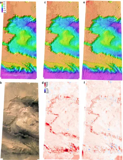
Figure 1 compares our Candor Chasma DTMs from Kirk et al. (2006a; 2006b; 2006c) and Kirk et al (2014) at which point the software and procedures described here were mature though not yet released, with MOLA altimetry. The use of NGATE with multi-way matching in the 2014 model greatly reduces the discrepancies between the stereo DTM and altimetry on the steep walls of the canyon. The difference between the 2014 stereo DTM and the interpolated MOLA DTM has a mean ± standard deviation of 30 ± 118 m excluding the areas of obvious edge effects visible in Figure 1f. These differences partly reflect the poorer sampling of the MOLA data set. A similar comparison to the point cloud of MOLA measurements gives a difference of 36 ± 98 m which compares favorably to the statistics of 11 ± 84 m for the standard team product and 50 ± 122 m for the USGS DTM reported by Heipke et al. (2007). It should also be noted that the 2007 comparison was based on only two MOLA tracks whereas the statistics reported here are derived from about 120 tracks.
Figure 2 illustrates the improvement in topographic detail from MOLA to the standard HRSC team DTM and our 2006 and 2014 DTMs for an area of the canyon floor with relatively good image texture. The improved resolution and geologic plausibility of the topographic model after refinement by shape from shading (Kirk et al. 2006a; 2006b; 2006c) is also illustrated.
4.2 Nanedi Vallis
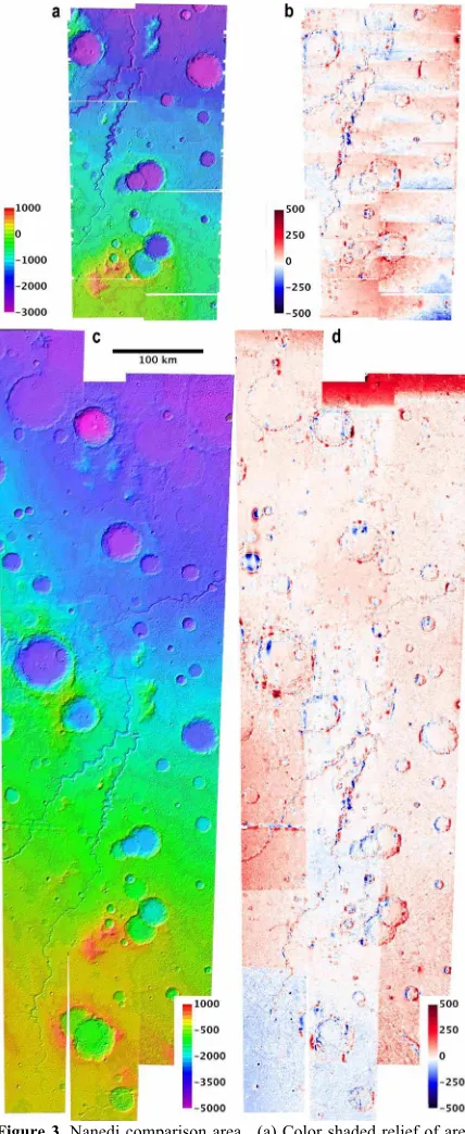
MOLA is -1.4 ± 57 m for the DTM in Fig. 3, -0.5 ± 44 m for the individual points, excluding these end effects. Once again, the limited resolution of MOLA contributes significantly to this difference. This statistic includes the area toward the bottom of the westernmost orbit (h0927_0000) for which the S2 image was unavailable between latitudes 4° and 7°. The stereo DTM deviates from MOLA by about 50 m here. The increasing discrepancy between adjacent orbits toward the south, where their overlap decreases and eventually vanishes, is also noteworthy.
Because the SOCET SET adjustment tool MST only performs linear adjustments to trajectory and quadratic adjustments to camera pointing for pushbroom images, we were concerned that long-arc images could not be controlled at satisfactory precision without breaking them into smaller sections. The stereo-MOLA discrepancies in Fig. 3d, however, plausibly relate more to the image coverage and overlap than to unmodeled along-orbit orientation variations.
Figure 4 shows closeups of part of the Nanedi Vallis channel itself. Our current DTM shows improved inter-orbit consisten-cy over our 2006 product and resolution compared to the DLR product from Heipke et al. (2007) though it should be emphasized that the standard processing pipeline has been continuously improved since then (e.g., Gwinner et al. 2009; 2010b). Orbit h0894 yielded a noisier DTM than its neighbors, and this is directly traceable to greater noise in the images, probably due to poorer atmospheric conditions.
4.3 Gale crater
Kirk et al. (2011) used the extensive HiRISE DTM coverage of the candidate MSL landing site in Gale crater to evaluate the multi-orbit HRSC DTM (Gwinner et al. 2010a). Such a relative comparison cannot address absolute accuracy, but given the large ratio in pixel scales (0.25 vs 12.5 m comparing to increasingly smoothed versions of the higher resolution DTM provides information about both resolution and precision.
Figure 5 shows the standard deviation of the difference between our h4235_0001 Gale DTM and the HiRISE reference, and also the released Level 4 DTM, as a function of smoothing of the HiIRISE model. The best fit for our model occurs with a (boxcar) lowpass filter size of 350 m and the residual deviation, a measure of precision, is 13.25 m. The Level 4 DTM matches this RMS deviation at the same smoothing but most closely resembles the HiRISE DTM smoothed with a 700 m filter, with a RMS deviation of 11.3 m. This is very similar to the result of Kirk et al. (2011) for the multi-orbit DTM, 12.5 m RMS for a 700m in filter width. We conclude that (a) our processing and Figure 2. Details of Candor Chasma floor from Fig. 1. (a) Nadir image. (b) Shaded relief from MOLA DTM. (c) HRSC standard product from 2007. (d) USGS DTM from 2006. (e) USGS DTM from 2014 showing improved resolution. (f) 2006 DTM refined by photoclinometry (shape from shading) resulting in more realistic topographic details.
Figure 3. Nanedi comparison area. (a) Color shaded relief of area mapped in 2006. (b) Difference of 2006 DTM from MOLA, showing artifacts related to the segmentation of the images by exposure time. Note different color scale from Fig. 1d and f. (c) DTM covering the full longitude extent of 3 orbits, presented for the first time in this work. (d) Difference between current DTM and MOLA.
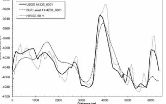
that of the HRSC team are achieving generally comparable results but making slightly different tradeoffs between DTM resolution and precision (SOCET SET offers the capability to control this tradeoff, and manual editing provides a means to eliminate the most severe errors while preserving resolution elsewhere); and (b) a precision comparable to the nadir pixel scale is achieved but the horizontal resolution is 15-30 times coarser, substantially different from the theoretical minimum DTM resolution of 3-5 image pixels (based on matching with image patches no smaller than 3-5 pixels across) that is frequently quoted in the literature (e.g., Kirk et al. 2008) and somewhat poorer than the empirical results presented by Heipke et al (2007). This discrepancy deserves further investigation. Figure 6 shows an example of collocated profiles through the DTMs (without smoothing) near the base of Aeolus Mons. It shows little evidence of horizontal misregistration, which would tend to increase the smoothing needed to achieve the best fit.
5. SOFTWARE AVAILABILITY
The software described here is, for the most part, already available to the planetary community. The HRSC sensor model and translation programs will be included in an upcoming ISIS3 release and the USGS pushbroom sensor model for SOCET SET is available on request from PlanetaryPhotogrammetry
@usgs.gov, as is documentation of our Standard Operating
Procedures (SOPs) for HRSC processing. The Ames Stereo
Pipeline, including the surface fitting program pc_align used in
our workflow, is available at https://ti.arc.nasa.gov/tech/asr/ intelligent-robotics/ngt/stereo/. For those who do not have their own SOCET workstations, access to workstations at the USGS, Flagstaff is available through the Planetary Photogrammetry Guest Facility (Kirk et al. 2009).
6. FUTURE WORK
The main challenge currently facing us is that BAE Systems introduced a new processing system called the Geospatial eXploitation Package (GXP) as the successor to SOCET SET in
2006. It has taken the intervening decade for BAE to incorporate full photogrammetric capabilities in GXP and for us to work with them to eliminate Earth-specific restrictions originally built into the new system. GXP allows for user-defined “plug in” sensor models but uses a new standard for them, the Community Sensor Model (CSMWG 2010). We have worked closely with the CSM Working Group to generalize the standard so it can be used for planetary work (Hare and Kirk 2017) and BAE has recently delivered the source code for a CSM version 3.0.2 of the “generic” (but not multi-line) pushbroom sensor model that we had developed for SOCET SET. Several teams (Astrogeology along with Arizona State University and the University of Arizona) are working together to develop new operating procedures for GXP. Our progress can be followed as well as any released documentation and any required code or routines will be available from: https://github.com/USGS-Astrogeology/socet_gxp_dev. We anticipate releasing an initial GXP-compatible CSM 3.0.2 version of the HRSC sensor model for the planetary community by the end of 2017 and are working with BAE to open source the CSM code in early 2018. Training on SOCET SET at the Planetary Photogrammetry Guest Facility in Flagstaff has been placed on hold for the past year, but we envision resuming training for DTM production with GXP in the near future. Finally, we have begun to convert the ISIS2 photoclinometry program pc2d (Kirk et al. 2003) to an ISIS3-compaitble Python application, and completion of this project will make it straightforward to produce enhanced DTMs similar to Fig. 3f.
7. CONCLUSION
We believe that the HRSC stereo processing pipeline that we have developed in ISIS3 and SOCET SET (and soon in GXP) provides a significant added capability to the planetary community even given the outstanding efforts of the instrument team to produce systematic products. With our software, users can make their own DTMs and orthoimages in advance of the release of high level data, make their own tradeoffs between DTM precision, resolution, and editing time, and leverage the photometric and other analysis capabilities of ISIS3.
ACKNOWLEDGEMENTS
We gratefully acknowledge the support of the NASA Mars Express Project, the Planetary Geology and Geophysics Cartography program (2005-2015) and the NASA-USGS Interagency Agreement for planetary mapping (2016 on) for the work described here.
REFERENCES
Acton, C., 1999. SPICE Products Available to the Planetary
Science Community, Lunar Planet. Sci., 30, #1233.
Batson, R. M., 1995. Cartography, in Planetary Mapping (R.
Greeley and R. M. Batson, Eds. ), Cambridge Univ. Press, Cambridge,, 86–94.
Community Sensor Model Working Group (CSMWG), 2010. Community Sensor Model Technical Requirements Document, v. 3. 0, NGA. STND. 0017_3.
Edmundson, K. L., Cook, D. A., Thomas, O. H., Archinal, B. A., and Kirk, R. L., 2012. Jigsaw: The ISIS3 bundle adjustment for extraterrestrial photogrammetry, International Annals of Photogrammetry, Remote Sensing, and Spatial Information Sciences, I-4, 203-208.
Eliason E. M., 1997. Production of Digital Image Models
Using the ISIS System. Lunar Planet. Sci., 28, 331
Golombek, M., et al., 2012. Selection of the Mars Science
Laboratory landing site, Space Science Reviews, 170,
641-737, doi:10. 1007/s11214-012-9916-y. Figure 5. Standard deviation of the difference between USGS and
HRSC Team Level 4 DTMs for rugged terrain on Aeolus Mons. Error level for the products is similar when evaluated at 350 m smoothing, suggesting they simply make different trades between resolution and precision.
Gaddis, L., Anderson, J., Becker, K., Becker, T., Cook, D., Edwards, K., Eliason, E., Hare, T., Kieffer, H., Lee, E. M., Mathews, J., Soderblom, L., Sucharski, T., Torson, J., McEwen, A., Robinson, M., 1997. An Overview of the Integrated Software for Imaging Spectrometers (ISIS), Lunar Planet Sci., 28, 387
Gwinner, K., and 34 others, 2016. The High Resolution Stereo Camera (HRSC) of Mars Express and its approach to science analysis and mapping for Mars and its satellites, Planet. Space Sci., 126, 93–138.
Gwinner, K., Scholten, F., Spiegel, M., Schmidt, R., Giese, B., Oberst, J., Heipke, C., Jaumann, R. and Neukum, G., 2009. Derivation and Validation of High-Resolution Digital Terrain Models from Mars Express HRSC-Data. Photogrammetric Engineering & Remote Sensing 75(9), 1127–1142.
Gwinner, K., Oberst, J., Jaumann, R., and Neukum, G., 2010a. Regional HRSC Multi-Orbit Digital Terrain Models for the Mars Science Laboratory Candidate Landing Sites, Lunar Planet. Sci., 41, #2727.
Gwinner, K., Scholten, F., Preusker, F., Elgner, S., Roatsch, T., Spiegel, M., Schmidt, R., Oberst, J., Jaumann, R., and Heipke, C., 2010b. Topography of Mars from global mapping by HRSC high-resolution digital terrain models and orthoimages: Characteristics and performance, Earth Planet. Sci. Lett., 294, 506–519.
Hare, T. M., and Kirk, R. L., 2017. Community Sensor Model Standard for the Planetary Domain, Lunar Planet. Sci., XLVIII, #1111.
Heipke, C., Oberst, J., Albertz, J., Attwenger, M., Dorninger, P., Dorrer, E., Ewe, M., Gehrke, S., Gwinner, K., Hirschmüller, H, Kim, J. R., Kirk, R. L., Mayer, H., Muller, J. -P., Rengarajan, R., Rentsch, M., Schmidt, R., Scholten, F., Shan, J., Spiegel, M., Wählisch, M., Neukum, G., and the HRSC Co-Investigator Team, 2007. Evaluating planetary digital terrain models: The HRSC DTM Test, Planet. Space Sci., 55, 2173–2191, doi:10. 1016/j. pss. 2007. 07. 006.
Kirk, R. L., Thompson, K. T., Becker, T. L., and Lee, E. M., 2000. Photometric modelling for planetary cartography, Lunar Planet. Sci., XXXI, #2025.
Kirk, R. L., Thompson, K. T., and Lee, E. M., 2001. Photometry of the martian atmosphere: An improved practical model for cartography and photoclinometry, Lunar Planet. Sci., XXXII, #1874.
Kirk, R. L., Barrett, J. M., and Soderblom, L. A., 2003. Photoclinometry made simple…?, ISPRS Working Group IV/9 Workshop "Advances in Planetary Mapping 2003", Houston, March 2003, online at http://astrogeology. usgs. gov/Projects/ISPRS/Meetings/Houston2003/abstracts/Kirk_ isprs_mar03. pdf.
Kirk, R. L., Edmundson, K. L., Howington-Kraus, E., Redding, B., Thomas, O., Jaumann, R., and the HRSC Co-Investigator Team, 2014. Practical processing of Mars Express HRSC images in ISIS and SOCET SET, 8th International Conference on Mars, Pasadena, CA, 14–18 July 2014, #1161.
Kirk, R.L., Howington-Kraus, E., Galuszka, D., Redding, B., Antonsen, J., Coker, K., Foster, E., Hopkins, M., Licht, A., Fennema, A., Calef, F., Nuti, S., Parker, T.J., and Golombek, M.P., 2011. Near-complete 1-m topographic models of the MSL candidate landing sites: Site safety and quality evaluation, European Planetary Science Conference, 6, abstract EPSC2011-1465.
Kirk, R. L., Howington-Kraus, E., Galuszka, D., Redding, B., Hare, T. M., Heipke, C., Oberst, J., Neukum, G., and the HRSC Co-Investigator Team, 2006a. Mapping Mars with HRSC, ISIS, and SOCET SET, Lunar Planet. Sci., XXXVII, #2050.
Kirk, R. L., Howington-Kraus, E., Galuszka, D., Redding, B., and Hare, T. M., 2006b. Topomapping of Mars with HRSC Images, ISIS, and a commercial stereo workstation, International Archives of Photogrammetry, Remote Sensing, and Spatial Information Sciences, XXXVI, Part 4, "Geospatial Databases for Sustainable Development", Goa. Kirk, R. L., Howington-Kraus, E., Galuszka, D., Redding, B.,
and Hare, T. M., 2006c. Topomapping of Mars with HRSC images, ISIS, and a commercial stereo workstation, EPSC2006-A-00487, European Planet. Sci. Conf. 2006. Kirk, R. L., Howington-Kraus, E., Rosiek, M. R., Anderson, J.
A., Archinal, B. A., Becker, K. J., Cook, D. A., Galuszka, D. M., Geissler, P. E., Hare, T. M., Holmberg, I. M., Keszthelyi, L. P., Redding, B. L., Delamere, A. W., Gallagher, D., Chapel, J. D., Eliason, E. M., King, R., McEwen, A. S., and the HiRISE Team, 2008. Ultrahigh resolution topographic mapping of Mars with MRO HiRISE stereo images: Meter-scale slopes of candidate Phoenix landing sites, J. Geophys. Res., 113, E00A24, doi:10. 1029/2007JE003000.
Kirk, R. L., Howington-Kraus, E., and Rosiek, M. R., 2009. Build Your Own Topographic Model: A Photogrammetry Guest Facility for Planetary Researchers, Lunar Planet. Sci., XL, #1414.
Lin S.-Y., Muller, J.-P., Mills, J. P., Miller, J. E., 2010. An assessment of surface matching for the automated co-registration of MOLA, HRSC and HiRISE DTMs. Earth and Planetary Science Letters, 294, 520–533.
Miller, S. B., Walker, A. S., 1993. Further developments of Leica digital photogrammetric systems by Helava. In: ACSM/ASPRS Annual Convention and Exposition Technical Papers, vol. 3, 256–263.
Miller, S. B., Walker, A. S., 1995. Die Entwicklung der digitalen photogrammetrischen Systeme von Leica und Helava. Z. Photogramm. Fernerkundung 63 (1), 4–16. Moratto, Z. M. ; Broxton, M. J. ; Beyer, R. A. ; Lundy, M. ; .,
2010. Ames Stereo Pipeline, NASA's Open Source Automated Stereogrammetry Software, Lunar Planet. Sci., XLI, 2364.
Neukum, G., Jaumann, R., the HRSC Co-Investigator Team, 2004. HRSC: The High Resolution Stereo Camera of Mars Express. ESA Special Publications SP-1240.
Scholten, F., Gwinner, K., Roatsch, T., Matz, K., Wahlisch, M., Giese, B., Oberst, J., Jaumann, R. and Neukum, G., 2005. Mars Express HRSC Data Processing-Methods and Operational Aspects. Photogrammetric Engineering and Remote Sensing, 71(10), 1143–1152.
Sides, S.C., Becker, T.L, Becker, K.J., Edmundson, K.L, Backer, J.W., Wilson1, T.J., Weller, L.A., Humphrey, I.R., Berry, K.L, Shepherd, M.R., Hahn, M.A., Rose, C.C, Rodriguez, R., Paquette, A.C., Mapel, J.A., Shinaman, J.R., Richie, J.O., 2017, THE USGS Integrated Software for Imagers and Spectrometers (ISIS 3) Instrument Support, New Capabilities, and Releases, Lunar Planet. Sci., XLVIII, #2739.
Smith, D. E., et al., 2001. Mars Orbiter Laser Altimeter: Experiment summary after the first year of global mapping of Mars. J. Geophys. Res., 107, 23,689–23,722.
Torson J., and Becker K., 1997. ISIS - A Software Architecture for Processing Planetary Images, Lunar Planet. Sci., 28, 1443.
Zhang,, B., Miller, S., DeVenecia, K., and Walker, S., 2006. Automatic terrain extraction using multiple image pair and back matching. Paper presented at ASPRS 2006 Annual
Conference, Am. Soc. Photogramm. Remote Sens., Reno,
Nevada, 1–5 May 2006.