______________________
SUBSPACING BASED ON CONNECTED OPENING SPACES AND FOR DIFFERENT
LOCOMOTION TYPES USING GEOMETRIC AND GRAPH BASED
REPRESENTATION IN MULTILAYERED SPACE-EVENT MODEL (MLSEM)
A. A. Khan a, *, T. H. Kolbe a
a
Institute for Geodesy, GIS, and Land Management, Technische Universität München, Arcisstraße 21 D-80333München, Germany - [email protected], [email protected]
Commission II, WG II/2
KEY WORDS: 3D subspacing, Constraints of locomotion types, CityGML, Multilayered Space-Event Model
ABSTRACT:
Indoor navigation has to deal with more issues as compared to outdoor navigation. Those issues include but are not limited to; need more level of detail to process enclosing area around navigating subject or object, consideration of the context of navigation (about locomotion type and its operating environment), and dealing with unconstrained indoor space for accurate results. Because of these complex issues, most of the frameworks for indoor navigation support for only one single type of locomotion, i.e. either walking, driving, or flying. And this decision to select a specific type of locomotion results in restricting the use of representation of indoor space for other types of locomotion e.g. graph-based abstraction of indoor space for driving cannot be used for flying.
In this work, we addressed the problem of supporting different types of locomotion in indoor space by determining 3D navigable subspace for the given locomotion type based on its physical constraints. While determining 3D subspace, we focused on some issues that include indoor space representation, precision of subspace computation, and “the consideration of the context of navigation” (about indoor space and the locomotion type). To achieve better representation of indoor space, the subspaces are determined based on the connected opening spaces. And for precise subspace computation according to the given locomotion type, we used the geometric methods i.e. configuration space from robotics field. Furthermore, a semantically enriched 3D indoor virtual model in CityGML format and different locomotion types (flying, driving, and walking) containing information (semantics, geometry, and topology) were considered to examine the context of navigation. Last but not least, the subspacing procedure was presented and implemented in a sound mathematical framework i.e. Multilayered Space-Event Model (MLSEM) as proposed by Becker, Nagel, and Kolbe in 2008 and 2009.
1. INTRODUCTION
3D Indoor navigation deals with many complex issues, one of those issues include the importance of the consideration of “the context of navigation” (Becker et al., 2009). “The context of navigation” emphasizes to consider the type of locomotion and the context of its navigating environment. Once we consider the type of locomotion then there is always need to determine navigable and nonnavigable space considering its navigating requirements. The navigating requirements are defined on the information of the locomotion type that is gathered from its properties and behaviours. The requirements are formalized into distinctive constraints (Khan and Kolbe, 2012) need to be fulfilled for its smooth navigation. Simultaneously, the contextual information about the subject’s navigating environment is collected from 3D semantically enriched virtual models in the form of information or rules from each navigational cell provided by its data models e.g. CityGML and Industry Foundation Classes (IFC).
The virtual models based on international standards like CityGML and IFC to represent indoor environments containing semantic, topology, and geometry information are very well known in 3D GIS domain. These virtual models are abstracted to network models through graph based methods to represent indoor environment (Lee, 2004) or navigable space for the given locomotion type. These network models are easy to manage, and represent the real situation of indoor space in the easiest possible way to comprehend and to navigate for the user
(Meijer and Zlatanova, 2005). But in many cases, they are very abstract to depict the complex situation of indoor space, lack the precision, and metric information of indoor environment. On the other hand, geometric based methods e.g. configuration space to represent and determine navigable space in indoor environment are very precise and contain metric information along with more level of detail (Lozano and Wesley, 1979).
The availability of 3D virtual semantic models of indoor environment, methods to represent them in network models, and geometric methods to determine navigable and nonnavigable space with accurate results provide an opportunity to consider them for subspacing for the different locomotion types (flying, driving, and walking). Here, subspacing refers subdivision of indoor space based on physical considerations. We require the result of subspacing should be precise (determination of navigable space at the lowest level of detail based on geometric methods e.g. configuration space), abstract (indoor space is abstracted based on graph methods), and take into consideration of the context of navigation (here we are focused on type and physical constraints of the locomotion type).
Though few models try to solve all those requirements (precise, abstract, and take into consideration of the context of navigation) in a unified architecture. However, none of them are capable of determining navigable and nonnavigable space for different locomotion types in a unified framework. In this paper, we address the problem of supporting different locomotion types through dealing with their subspacing in semantically enriched 3D indoor environment. We propose a method to
ISPRS Annals of the Photogrammetry, Remote Sensing and Spatial Information Sciences,
determine accurate navigable and nonnavigable subspaces using geometric and graph based methods in a static 3D semantic virtual environment. The semantic 3D environment representation is based on an international standard i.e. CityGML and 3D topology-geometry consistency model. The environmental model is analyzed to extract topology and generate a precise network model. Furthermore, this network and geometric model is subspaced for better representation of complex situations and then used to determine accurate navigable and nonnavigable space for different locomotion types based on geometric methods.
This paper is structured as follow. In section 2 related work is investigated. Section 3 describes method of environment representation, section- 4 discusses multilayered space-event model, and section 5 presents subspacing. In section 6 implementation is shown. At the end, the conclusion is discussed.
2. RELATED WORK
Representation of 3D environments and route planning are intensively studied in configuration space and 3D GIS fields. We are interested in how physical space structure is abstracted for route planning in two different domains i.e. 3D GIS and configuration space. The physical abstraction methods are closely related with the environment representation because the abstractions (network models) are created from these environments. Therefore, we considered the environment representation methods used in aforementioned domains. Our prime focus is on the strengths of abstraction and representation methods, and explores that how we can incorporate methods from both domains to fulfil our requirements (precise, abstract, and considering the context of navigation) in determining navigable and nonnavigable space according to the different locomotion types. A short background of the representation and abstraction methods used in configuration space and 3D GIS are given below.
2.1 Map representation methods/ models in Configuration Space
The methods to represent the environment are categorized into three areas by Wise and Bowyer (2000); boundary representation methods, division and classification methods, and hybrid methods. Each method has strengths and limitations, and selection of method depends on a number of applications and its specific factors e.g. the number and types of degree of freedom. Boundary representation methods: The boundary representation of moving object and obstacle in configuration space is generated using two main concepts such as the Minkowski sum and contact surface. The configuration space obstacle boundary of a mobile robot is constructed by the growing obstacle using the Minkowski point set operations for 2D and 3D objects. The obstacle boundary with translating and rotation can be generated with interaction of surfaces between obstacle and moving object.
Division and classification methods: In this method the environment is divided into a number of cells. Furthermore, each cell is distinguished as safe, prohibited, or contact based on some test. Based on different division strategies the environment is represented as grid, raster, or axially aligned boxes.
Hybrid methods: In hybrid methods they use combination of boundary and division representation methods e.g. for map representation the space is divided into cells obstacles are grown by Minkowski sum.
2.1.1 Space abstraction methods (geometric based)
The methods to solve the basic motion planning problem are based on some general approaches: cell decomposition, roadmap, and potential field. We are interested in the abstraction methods used in these approaches to simplify the motion planning problem for the robot.
Cell decomposition: In this approach, the robot’s free space is divided into simple regions called cells. A non-directed graph representing node as cell and edge as adjacency relation between the cells is constructed. The graph is searched for the continuous free path from initial to final configurations of robot. This approach is based on exact or approximate cell decomposition methods.
Roadmap: In the roadmap method, the robot’s free space is captured in a network consists of edges and vertices. Once network model or roadmap is developed, it is used as a set of paths to search the most favourable connecting path from start to target point of robot. Different methods are used to compute different types of roadmaps from the free space. Those methods include visibility graph, voronoi diagram, freeway net, and silhouette.
Potential field: The configuration space is discretized into a regular grid of configurations and uses this grid to search for free path. The method uses heuristics to guide the search. These heuristics take the form of functions known as potential fields. According to this method, the robot is represented as a point in configuration space is a particle moving under the influence of an artificial potential generated by the goal configuration and configuration obstacles. The goal configuration and configuration obstacles produced attractive and repulsive potential respectively. At every configuration, the direction of this force is considered the most favourable direction of motion. The roadmap and cell decomposition methods first analyze the free space and then construct the graph. In potential field method, there is no pre-processing step to analyze the connectivity of free space. Most of the times we need whole free space knowledge to determine free paths. To have whole free space into account roadmap and cell decomposition methods are used as global and potential field method as local method to determine free path for the robot.
2.1.2 Route planning methods
The geometric methods of space abstraction and representation are very often used in motion planning applications in Robotics field to represent obstacle and free space (Latombe, 1991). In the following paragraph, we discussed some of the route planning concepts common in geometric based methods. The shortest route planning problem based on geometric location map remains a very old fatigue. Holmes et al., (1992) and Holmes (1989) presented a geometrical shortest route method by partition of plane into tiles and addressing the shortest path queries in 2D through graph and funnel growth approach. Hershberger and Suri (1993) introduced an algorithm by quad-tree style, subdivision of the plane and through propagation of wave front from a source point in the presence of polygonal obstacles. This computes a planer map which is further used to compute the shortest path from fixed source point to all other points of the plane. Papadimitriou (1985) presented a new method to answer the shortest path problem by dividing each edge in a set of segments by introducing points. The visibility graph is constructed based on segments from all edges of obstacles, including start and target point. After computing a nominal cost for each edge (Euclidean distance), Dijikstra’s shortest path algorithm to the weighted graph is applied to get the shortest path from start to target point. The idea of configuration space by Lozano (1979) in robot motion planning is to represent the robot as a point, map the
contact-ISPRS Annals of the Photogrammetry, Remote Sensing and Spatial Information Sciences,
free configurations space, and represent the configuration-obstacle space that is nonnavigable or unsafe for the robot has simplified the route planning problem. Furthermore, Han et al. (2002) proposed a method to determine navigable route in indoor facility for wheelchair based on Lozano (1979)’s technique. In this method, the navigable route is determined through simulating behaviour of wheelchair in the configuration of the indoor facility. The route planning methods discussed here are very precise with different complexities depending on the application specific factors.
2.2 Map representation methods/ models in 3D GIS
The introduction of 3D semantics building models have lead to increase the focus of users from only visualization towards semantics information about the model and its components. In 3D GIS, the 3D building models to represent the environment are categorized based on their spatial and semantic characteristics.
Semantic models: Semantic models are those models that not only focus on geometry but also on semantics, topology, and appearance of objects. In 3D GIS, two international standards for the representation of semantics 3D building models i.e. CityGML and IFC are frequently in use. The details about both representations can be accessed from sources (CityGML, IFC). Geometric models: The pure geometric models are very common in computer graphics systems. These models are generally consist of geometry and do not contain any thematic or semantic information related to objects. They emphasized on visualization of the object rather than semantics, topology or hierarchical relationship of object components. These models include Google Sketchup, Autodesk’s 3D Studio Max, 3D CAD models, etc.
Topological models: These models represent the information about an object’s continuity and its connectivity with its neighbourhood. The topological models consist of nodes and edges representing objects and their relationships with its neighbouring objects through graph theory. A well known topological data model Node-Relation Structure (NRS) to interpret topological relationships through the Poincaré duality, contains adjacency, connectivity, and hierarchical information between 3D objects (Lee, 2004). Another topological model in 3D GIS is the map tree model that contains adjacency tree and combinatorial map. Adjacency tree consists of nodes represents regions and edges between nodes represents that the nodes (regions) share a common boundary. And combinatorial map represents in the form of a triple of cycles of semi-edges, darts, and is embodied in such as the winged-edge representation (Worboys, 2011). In addition to these models, there is LEGO model to represent the indoor space by using different types of cubes. In this model, cubes are merged to form maximum accessible blocks and then LEGO graph is constructed representing each cube as node (Yuan and Schneider, 2011). Hybrid models: There are many graph based models which are further geometrically embedded to achieve precise navigation results. For example, Meijer et al. (2005) model that is graph based and it is embedded geometrically for more precision in route planning. And there is a hybrid user centric indoor navigation system presented by Anagnostopoulos et al. (2005), which is based on graph and geometric representations. Apart from both representations, it also considers user’s physical and perceptual characteristics, and considering the rules of semantic it finalizes the route plan for the user.
2.2.1 Space abstraction methods (graph based)
Most of the network models that are abstracted to represent the space based on geometric abstraction methods operate on pure
geometric rules. However, in 3D GIS, apart from pure geometric rules, semantic and other concepts e.g. hierarchical are being considered during abstraction process. The main reasons to consider the semantics and other concepts during abstraction process are to make the network model more precise and to accommodate the representation requirements of semantically enriched 3D models. Here, we are interested in the methods used to abstract the 3D building models for route planning. Some of the important space abstraction methods are as follow:
Node Relationship Structure: The Node-Relation Structure (NRS) by Lee (2004) is to simplify the complex spatial relationships between or among 3D objects. Furthermore, it uses Straight-Medial Axis Transformation (S-MAT) modelling to represent the geometric properties of the object in the dual graph. An abstraction method presented by Stoffel et al. (2007) use hierarchical relationship of building components into hierarchical graph and makes partition of non-convex region into non-overlapping convex sub-regions. On the basis of partitioning, navigational graph for the physical space is defined and the paths between boundary nodes are represented. There is another abstraction method used for semantic 3D building models presented by Gröger and Plümer (2010), in this method a derivation tree is generated based on the constraints and grammar rules of the semantic 3D building model. Then, a graph is constructed from derivation tree for the same building model.
2.2.2 Route planning methods
After constructing graph using abstraction methods of 3D GIS. The different algorithms of the shortest route e.g. Dijkstra are applied on the graph to achieve the shortest route between initial point and final point.
2.3 Advantages and challenges of using geometric and graph based methods
Some of the advantages of using geometric based methods are a follow.
1. The geometric based approaches, which are already in place in robotics field to represent navigable and nonnavigable space have more level of detail. They are very accurate to deal with geometric constraints of the locomotion type in indoor space (Latombe, 1991). 2. The geometric based methods are very precise, even in
complex situations of indoor structures to determine navigable space (Han et al., 2002).
3. Most of the route planning methods based on geometric approaches focus at the micro environments to achieve optimal route e.g. within a room environment.
4. There are well defined methods to determine unsafe regions for the specific locomotion type considering its geometry (Lozano, 1979).
Challenges:
1. There is no consideration of semantics of 3D virtual models in abstraction of space; the abstraction is done on geometric basis.
2. The geometric methods are complex to manage and store. Advantages of using graph based methods:
1. Graph based methods are easy to manage and store. 2. They represent the complex physical situations in the
easiest available way to comprehend for the user. 3. Simple to locate and navigate to its neighbourhood. 4. Most of the route planning methods in 3D GIS, which are
graph based focus on the macro environments e.g. room A to room B or Building A to Building B.
ISPRS Annals of the Photogrammetry, Remote Sensing and Spatial Information Sciences,
Challenges:
1. Many researchers argue that the graph based methods lack the precision of geometric models in terms of metrics for location and distance (Kolodziej and Hjelm, 2006), (Meijer et al., 2005), (Stoffel et al., 2007).
2. There is no specific method or concept to determine unsafe region through representation and abstraction methods of 3D GIS.
From the above discussion, it can be observed that the methods used for the representation and abstraction of physical space in both domains have different strengths and limitations. The strengths of geometric methods (Han et al. 2002, Lozano 1979) include the precision and well defined methods to determine unsafe region. But the main challenges is that it is not considering any semantics during abstraction or representation of space. The strengths of abstraction methods ( Stoffel et al. 2007, Meijer et al. 2005, Lee 2004 ) in 3D GIS include the embedding of other models e.g. semantics model with the geometric methods to achieve higher precision in navigation and route planning. Although, they lack the precision of geometric models in terms of determing unsafe region for the subject.
Here, we have incorporated strengths in methods of abstraction and representation from both domains to address our own problem of subspacing for the different locomotion types considering their semantics, geometrics and topology constraints.
The subspace according to the specific locomotion type is determined through four steps process. The first step relies on environment representation, it should be semantically enriched and in a well known international 3D building model format to support for the context of navigation. The environment represented must be topologically and geometrically consistent to have reliable network model. The second step, the network/graph model must be representing the real situation of 3D indoor complex structure to the maximum extent, towards this objective we are subspacing the geometries on basis of connected opening spaces so the long corridors or rooms are represented with a number of sub geometries. In third step, it must determine navigable and nonnavigable space based on configuration space, which should be accurate and fulfill the constraints of the locomotion type. In last step, network model/ graph representing geometric model of indoor space should be flexible to adjust with other network models representing other infrastructures of environment. The representation results of the second and third steps must be integrated hierarchical and parallel with other network models to address 3D route queries efficiently.
Our approach for the representation of static environment is based on the international standard i.e. CityGML. And it is constructed based on the 3D city topology-geometry consistency model with the purpose to create a reliable network model. The network model, which is representing topographic layer of 3D building model, is embedded in MLSEM. Furthermore, this topographic layer is subspaced to utilize for better options in extra ordinary situations as well as for better route planning. In addition, subspacing is carried out to determine the subspace layers according to the locomotion type (Khan and Kolbe, 2012) based on their unique physical constraints and considering the concept given in Becker et al. (2009). Within MLSEM framework the proposal is made to determine accurate navigable and unsafe region for the specific locomotion type.
3. ENVIRONMENT REPRESENTATION AND
LOCOMOTION TYPES
3.1 Environment representation
The ultimate purpose of the virtual 3D models representation is to replicate the real environment of indoor space with semantic, topology, and geometry information. While representing the real environment it must also provide a reliable data structure for indoor analysis, indoor queries, and queries related to determination of navigable and nonnavigable space for a specific locomotion type. There are different standards of semantic 3D building models that represent the indoor environment. Each standard represents 3D indoor environment of building through a different approach. For example, CityGML represent the building based on surface observation of indoor objects, whereas IFC is based on BIM and Computer Aided Architectural Design (CAAD) representation approach. In BIM and CAAD models the building structure is represented with volumetric and parametric primitives.
We are expecting the following solutions from the environment representation model to address issues related to subspacing. 1. It must provide semantic, geometric, and topology
information based on an international data model standard. 2. It must provide observation based modelling of indoor
space because locomotion types are interacting with the surface areas (observation areas) of building model. 3. It must have support for a consistent topology relationship
between the surface areas. Thus we will be able to extract and check topology relationships for reliability.
The above mentioned expectations are fulfilled by CityGML standard representation except some variations with the third expectation. Typically, in practice the CityGML does not represent topological relations i.e. two adjacent wall surfaces are represented by two separated polygons; we will have to re-establish topology relations of surfaces within the building after reading the CityGML file. Thus, to avoid this complex step, we need some special treatment with the CityGML representation that is discussed in next section. Based on our expectation from indoor environment representation we are opting for CityGML standard to represent indoor environment.
Apart from geometry and semantic data consideration we need to consider the topology information of 3D virtual environment. The main purpose of topology computation is to determine navigable and nonnavigable space according to the constraints of the locomotion type. The topology computation will help to determine 3D space’s spatial relations and continuous navigable or nonnavigable spaces. To compute reliable and accurate results, there is need to have consistent and reliable 3D input data. To have a reliable 3D input data we need an efficient and reliable consistency topology and geometry checking model. Zlatanova et al. (2004) have discussed the topological models available for 3D spatial objects. Most of the models describe how to determine the topological relationship and do not give rules to define geometry that will be checked later for consistency. Gröger and Plümer (2011) have presented the concept of using 2D topology to check the consistency of 3D objects. They also presented the concept of geometry and topological consistency model to check the consistency of geometry and topology of City model objects. The concept of 2.8D map, which consists of connected cell complex embedded in 3D space that is single 2-manifold is used to achieve consistency for 3D city models (Gröger and Plümer, 2011b). Further, the solids are integrated with 2.8D map and volume objects (aggregations of solids) are used to represent building parts, buildings, and whole 3D city model. Additionally, the same authors presented transaction rules, following those rules,
ISPRS Annals of the Photogrammetry, Remote Sensing and Spatial Information Sciences,
the static and dynamic consistency checking of 3D city models in CityGML format can be achieved.
Here, to have the geometric and topology consistency to our environment representation model, we are following the model of Gröger and Plümer (2011b) with the concept of 2.8D map. Therefore, we are representing the building and building parts with composite surface solids (volume objects) using CityGML’s LoD-4 semantic representation model.
There are some considerations in representing building surfaces with volume objects that we have to consider. Those considerations are as follow.
1. The convex corner generated from two polygon surfaces cannot be represented with two solids because the solids representing surfaces will intersect their geometries at the corner. Therefore, to avoid intersection of two solids at the corner, we have to represent corner as individual solid that will share the surfaces of both solids.
2. Considering part of composite surface of 3D solid
We are using a 3D volume solid to represent a polygon surface of 3D building model. The properties like area, length, etc. of 3D solid are not equivalent as surface polygon. Therefore, we have to consider only a part of surface from composite surface of 3D solid for the properties to represent the polygon surface of building model. The selection of a surface part from composite surface of 3D solid is based on the surface area of 3D solid that must be connected/contain air space solid. Exception to this criterion is given to the 3D solid representing air space/room in building. That is considered with its complete surface for its properties.
3. Representation of door Surfaces (polygon) as solid
In CityGML the door is represented through different methods, a ring with double orientation; in a room case, one orientation of polygon directed towards interior of the room and another orientation directed toward outside of the room. Furthermore, this ring /polygon cannot be represented with a solid as it will intersect with each other due to opposite directions of the same polygon. In another case, the door is represented with two polygons with different surface ids, having mutual distance (equivalent to width of wall) and opposite orientation. Here, in our input data, we have the second case; we are creating a solid from the two opposite oriented polygons.
3.2 Locomotion types
The locomotion types considered for this work are walking, driving, and flying. Walking refers to leg(s), driving refers to wheeled based, and locomotion type that takes flight in the air is referred as flying. We consider an example of each type of locomotion that is common in use and represents the distinguished mobility mechanism in indoor environment. Each distinguished locomotion type defines its own constraint types for indoor navigation (Khan and Kolbe, 2012). The Wheelchair is considered as an example of driving or wheeled-based mechanism. Similarly, leg(s) based locomotion that is common and can be replicated as bipedal walking system in indoor environment as a walking person. Apart from these two locomotion types, micro Unmanned Aerial Vehicle (UAV) (Miniature UAV, Grozonka et al., 2009) is considered as an example for flying locomotion.
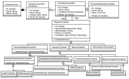
Each locomotion type has different physical constraints and these constraints determine the navigability of indoor space. The conceptual constraints model for each type of locomotion is presented in Figure 7 and the procedure to draw each constraint is given by Khan and Kolbe (2012). We exemplify some constraints of each locomotion type to determine subspaces, which are presented in implementation part of this work.
We used 3D sphere and 3D cylinder for the representation of geometric models of UAV and wheelchair respectively. The walking person is represented as a 3D cylinder with variation of height from the cylinder that is used for the wheelchair. During subspace determination, each locomotion type’s representation is supported with its specific constraints for indoor navigation. Some assumptions about our input data need to be initialized. Those assumptions include the input geometries are compatible with the geometric-topologic model presented by Gröger and Plümer (2011b). This geometric-topologic model emphasized on no gap or unrepresented space in model. In our case, in order to avoid complex modelling and computations, we are representing only visible surface areas of building. We have to give relaxation to this requirement. In addition, the input geometries (3D solids) must be valid according to the axioms given by Gröger and Plümer (2011a).
4. MULTILAYERED SPACE-EVENT MODEL
(MLSEM)
A MLSEM framework to integrate and represent different network graphs representing different infrastructures in navigation and localization of the subject or object was presented by Becker et al. (2009). MLSEM not only provide an efficient way to manage and represent the indoor environment but also provide an application schema IndoorML to store, localize, and navigate a subject/object in indoor environment. In addition, it is used for creating subspaces based on different considerations (Becker et al, 2009).The source (Khan and Kolbe, 2012) has provided a procedure and the constraints types on which different considerations can be made for subspacing. Most of the methods, which construct network graphs from 3D environment model do not use any semantically enriched environment as input data model. If even they have, they do not define a standard procedure to determine subspace for a given locomotion type (Schilling and Goetz, 2010), resulting in not supporting for different locomotion types. MLSEM through application schema IndoorML gives an opportunity to use semantically enriched 3D environment for the navigation and determining subspaces according to the given locomotion type. Additionally, MLSEM is based on sound mathematical rules, therefore, it is considered as an efficient framework to represent, integrate, store, and manage indoor environment. A brief introduction about MLSEM is as follow.
Multilayered Space-Event Model (MLSEM) is based on sound mathematical rules to represent multi layers in a uniform framework (Becker et al., 2009). Each layer is representing independent space schema and integrated into multilayered model. The individual layer constitutes a graph that is integrated with other layers with n-partite graph. A node in dual space represents volumetric cell from primal space and edge represents a transition between two states from primal space. The navigating subject or object will be in one state of each layer at a given time. Through a joint-state of multilayered model the subject or object is navigated or localized.
A space layer (e.g. topographic space) can be subdivided hierarchically based on a specific consideration e.g. type of locomotion. If there are different types of locomotion, this model allows forming a main layer (topographic layer) and then sublayers to facilitate the subspacing for each type of locomotion. The inter space connection relation between main layer and sub layers are represented as “contains”/ “inside” and “equal”. This concept allows for hierarchical grouping of space in a specific layer.
We used different types of locomotion and their physical constraints types presented in (Khan and Kolbe, 2012) to create
ISPRS Annals of the Photogrammetry, Remote Sensing and Spatial Information Sciences,
subspaces based on the concept given in source (Becker et al., 2009). The subspaces are determined following the procedure presented in Figure 8 and applying configuration space method. The subspacing within MLSEM is explained in following section.
5. SUBSPACING
In our work, we developed a main topographic layer from input 3D solid geometrics based on the method of MLSEM. We subspaced the main layer with the objective of having efficient results for 3D topological and route planning queries to facilitate different locomotion types considering their unique constraints.
The main topographic layer based on the method of MLSEM from topographic space is very abstract and need further subdivision to have better solutions particularly for indoor route planning. The details about subspacing indoor space based on connected opening spaces are as below.
5.1 Subspacing based on connected opening spaces
We do subspacing of indoor space because of the following reasons.
1. To have detail representation of indoor space e.g. a long corridor is represented with one node is very abstract, and result into unreliable route planning.
2. To achieve better route performance e.g. taking the central node of corridor, making adjusting line at the centre and creating nodes next to the doors points have better route performance as compared to only representing nodes of doors and corridors (Meijers et al., 2005).
3. To represent real situation of indoor space to maximum extent by representing obstacles or particular important spaces within indoor space (Marcus and Alexander, 2011). 4. To represent the indoor space in a more understandable
and manageable manner i.e. hierarchically, semantically or geometrically for its users (CityGML, IFC, Stoffel et at., 2007)
To deal with 3D route queries and for better performance of route planning based on above reasons and methods to subspace, the given physical indoor space needs to be subspaced geometrically. The methods (Meijers et al. 2005, Marcus and Alexander 2011) subspaced the given indoor space at the graph level for better performance, and based on floor surface of building (2D), here we are interested to subspace the indoor space at geometrical level and in 3D (that will result at graph level also).
Before having the 3D subspacing of a given indoor space we have to consider following points.
1. Subspacing must be based on a proper method, resulting in more subspaces to represent the whole main subspaced space.
2. Each subspace must contain a distinctive 3D space volume to be able to extract as a node in a graph uniquely. 3. The subspaces must have a positive effect on the
representation of space in terms of management or understanding as well as on route planning performance. Apart from the above points, keeping in view of our own situation we need to consider that this subspacing must support different locomotion types and it must be in 3D environment i.e. not dependant on 2D floor plans.
An object in indoor space always needs air/free space to perform navigation. Therefore, free space becomes one of the main parts of indoor environment to be considered for navigation. The free space needs to be subspaced at graph and
geometric level to represent the real situation to maximum extent. This can improve the performance of 3D route planning queries in indoor space. For example, if we represent whole room with one node then it is very abstract and for a route plan within a room we only have one option of central node, this could make the situation difficult and results into inefficient outcomes in route planning.
Considering the problem of inefficient results of route planning we need to subspace the air/free space further. When we observe the air space within a room or corridor then it is noticed that during route planning user always searches for the exit/entry point within a room. Therefore, it supports the following argument that the free space in the room adjacent to the connected opening space has always some importance as compare to the other indoor space in a room. Thus, we can subdivide indoor free/air space based on connected opening space objects. The Figure 1 shows the free space of a room connected with a door and a window. The opening objects connected with the free space of a room may be hole, air, and so on.
Figure 1. Spaces within room connected with opening spaces.
5.1.1 Method
The subspacing method is explained below based on two scenarios.
1. Opening space is represented as a ring or polygon: When the input dataset is represented in CityGML at LoD-4 and the opening space is represented as a ring or polygon with two different orientations that is adjacent to two rooms in an indoor environment. In this case, the ring or polygon of opening space i.e. door is taken as a boundary surface geometry between room and door, is extruded with the length equal to the radius (the reason to use radius is given section 5.2) of the locomotion type in its normal direction towards the room. In next step the extruded solid is deducted from the air space solid. After deduction, we have two solids representing the main space. 2. Opening space is represented with two polygons with opposite orientations: The opening space is formed as solid in IndoorML from two polygons with different Surface-IDs /orientations representing the same opening space e.g. door in CityGML. In a door’s case, the boundary geometry is computed between solids of door and room. The boundary geometry is a 3D polygon that is extruded into the room solid with the length equal to the radius of the locomotion type. Then the newly generated solid is deducted from the room solid forming two distinctive solids representing the room.
The method is realized on a 3D building model shown in Figure 2 including a corridor shown in Figure 5, results of subspacing are shown in Figures 3, 4, and 6.
Figure 2. The 3D building model before subspacing based on connected opening spaces (from top view).
ISPRS Annals of the Photogrammetry, Remote Sensing and Spatial Information Sciences,
Figure 3.The 3D building model after subspacing based on connected opening spaces (from top view).
Figure 4. A corridor highlighted after subspacing based on connected opening spaces.
Figure 5.The corridor geometry before subspacing (only one geometry representing corridor. Top view).
Figure 6.The corridor geometries after subspacing (7 geometries representing corridor. Top view).
5.1.2 Advantages
The subspacing of given indoor space cell based on connected opening space result in following advantages.
1. Indoor space that is represented with a single geometry can be represented with a number of geometries, giving more details to the indoor space.
2. Mostly, the subspacing methods that focus on the shortest route plan represent the indoor space depending on the 2D floor plans and on connected doors of room or corridor at the graph level but not at the geometrical level. By using this method, user can represent and subspace the given indoor space at geometric level and in 3D space.
3. If we consider a case where a corridor is subspaced into 10 nodes based on connected opening spaces, and a route was determined within that corridor for a specific locomotion type containing three nodes on graph based methods. Then to compute the shortest route at the geometric level user need to pick only three geometries as required for route computation. This will reduce the overheard cost of computation to handle whole geometry or all 10 geometries for the considered corridor.
4. This subspacing method of indoor space gives complementary information to the indoor space about existing opening space opportunities to be utilized for user in emergency or extra ordinary situations.
5. This subspacing method helps in decisions during route planning for different locomotion types. Because the flying vehicles prefer to use opening windows (particularly windows adjacent to above the doors) for route as compare to doors. Most of the route planning methods only rely on doors and floor plans for route planning, but in our case we are taking consideration of all the spaces within indoor space e.g. air space, floor surface, doors, windows, etc.
5.2 Subspacing based on locomotion types
After subspacing indoor space based on connected opening spaces, now we want to further subspace the indoor environment according to the different locomotion types. We considered different locomotion types (walking, driving, and flying) in a static environment composed of un-deformable hierarchical objects of 3D building modeled in CityGML format. There are different constraints types for each locomotion type in indoor space presented in Figure 7, based on those constraints they determine their navigability of indoor space cell. Following the subspacing procedure presented in Figure 8, each locomotion type will determine its own distinctive subspace layer and each subspace layer is integrated with the main topographic layer of indoor space based on the concept given and presented in sources (Khan and Kolbe 2012, Becker et al. 2009).
Figure 7. Conceptual model of constraints according to locomotion type (Khan and Kolbe, 2012).
The problem of determining navigable and nonnavigable space for the specific locomotion type starts with the assumption that we are given geometric, topology, and semantic descriptions of the objects in the workspace i.e. 3D CityGML building model. We are also given geometric and semantics descriptions of the locomotion type. Unlike with many basic path planning problems, there are no explicit obstacles for the locomotion type. The decision of obstacle has to be decided on individual object/ space cell based on the constraints of the locomotion type, the cell is consider obstacle, only if the constraints of the locomotion type are not fulfilled e.g. stair is obstacle for wheelchair if it does not has capacity to drive on stair.
The locomotion type navigates in a 3D environment thus configuration space is 3D. We represented environment CL into a 3D space solid cells. Each 3D solid cell contains a set of attributes Ca.
CL= X , Y, Z
X, Y, Z = { u.ca | 0 =< u < n }
Where ca defines the cell attributes and n the number of cells.
ISPRS Annals of the Photogrammetry, Remote Sensing and Spatial Information Sciences,
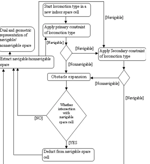
Figure 8. Flowchart of subspacing of 3D indoor space based on the constraints of the type of locomotion.
The attributes of each space cell contain semantics, topology or geometric information related to cell e.g. feature type, width, volume, etc.
To improve and simplify the representation of navigable and nonnavigable space for the specific locomotion type, the locomotion type’s geometric representations are simplified. The flying (unmanned aerial vehicle) locomotion is represented as 3D sphere whereas the walking (human being) and driving (wheelchair) locomotions are represented as 3D cylinder with variation of their height.
One might think of our method to approximate locomotion types and space cells will over simplify the work space. While this seems to be true, one of the contributions of this work is to demonstrate the ability of such system to determine navigable and nonnavigable subspaces using geometric methods for the specific locomotion type considering its constraints and using semantic 3D models.
In robotics motion planning, the crucial task of getting collision free space for the subject or object is known as global path planning or collision checking problem. Here, we are interested to determine the collision free or navigable space for each type of locomotion. We earlier assumed the geometries of the locomotion types as 3D sphere for UAV, and 3D cylinders with variations of height for human being and wheel chair. Sphere and cylinder models of locomotion types allow performing the collision check in constant time if the distance to the nearest object is known and the orientation dimension is ignored at the planning time based on some assumptions. The distance to the nearest object is computed by simply compared to the radius of the cylinder or sphere.
For the collision check we make following assumptions about the workspace and the locomotion types.
We assume that locomotion type:
1. Does not bend its body to pass an obstacle.
2. Particularly (humanoid and wheelchair) will always be in a stable position vertically, making always constant distance with the horizontal surface.
3. Whenever move or drive inclined obstacle e.g. ramp they will always make constant unsafe trajectory curve (arc of circle) whose distance will remain same that of radius of cylinder or sphere.
4. Is able to search and compute the require attribute of 3D space cell for its specific constraint.
5. Can compute the accessibility between two navigable spaces to determine the obstruction or unsafe region of obstacle.
Under these assumptions each locomotion type is able to determine its navigable and nonnavigable space map.
Each locomotion type contains physical properties with specific values e.g. height is 2 m, length is 3m, etc.
Locomotion type: L1 P1= { p1, p2, p3, p4, ..., pn}
Some of these properties take part in deciding 3D space cell is feasible for movement or not. Those properties, which take part exert requirements on 3D space cell to be fulfilled to make it navigable. These requirements become constraints of the locomotion type.
Constraints of locomotion type: L1 s1= {C1, C2, C3, C4, ..., n}
CL(Z) = Navigable, L1’s constraints s1 are fulfilled Nonnavigable, L1’s constraints s1
are not fulfilled
L1 constraints s1 are fulfilled: hc ϵ P1
hc= Height of locomotion type C1= { height of space cell > hc }
The locomotion type will search in attributes of 3D space cell and compute the height of the cell to compare with the height of the locomotion type hc.
C1(fulfilled) = fulfilled, hc <= height of 3D space cell
Not fulfilled, hc > height of 3D space cell
If 3D space cell Ci is declare obstacle for L1 because C1 (not fulfilled), On the other hand, Cj is declare navigable for L1 because set of constraints s1 are fulfilled. The relation between the two space cell boundaries are checked if their boundaries are in touch then the boundary space geometry of both geometries is computed.
Boundary space geometry G1= Ci ∩ Cj
In our case, we will get the boundary space geometry a 3D polygon as two geometries Ci and Cj are 3D solids. This boundary space geometry G1 will actually represent the surface of obstacle interfacing with the navigable space cell Ci. The clearance d (Cell) of cell Ci is defined as the minimum distance to boundary space geometry G1 or the obstacle cell Cj. The value of d (cell) is the Euclidean distance equalent to radii or heights of the cylinders or sphere representing the locomotion type L1. The computation of this value is implemented by obstacle expansion of obstacles until a distance d is reached. This computation can also be achieved using the Minkowski sum of the geometry representing the locomotion type (L1) and the boundary space geometry G1.
Further, we can define the free configuration space as
Cfree = { (x,y,z) ϵ C | Ci – Minkowski sum (geometry of L1, G1)}
Once the free space is defined then we are interested to determine the dual representation of whole navigable space for
ISPRS Annals of the Photogrammetry, Remote Sensing and Spatial Information Sciences,
the specific locomotion type. Each navigable space cell is represented with a node. The two space cells, if they are connected and accessible from one cell to the other for the locomotion type, are represented with an edge.
In free space cell Ci, applications of some constraints C2 of locomotion type create obstruction (nonnavigable space) and the decision to create that obstruction from the obstacle area depends on accessibility between two navigable spaces, if only if the constraints of the locomotion type are fulfilled to access from one space cell to another or overcome the obstacle space then it will not create obstruction otherwise it will. The obstruction space is deducted from the free space cell and then the dual space representation of the free space cells for the specific locomotion type is built.
We compute the growing region of nonnavigable space of the 3D environment based on Minkowski sum method. Further, we presented the dual representation of whole navigable space, which reflects the impact of the type and constraints of the locomotion on navigable space of 3D environment. At the end, each subspace will form a unique layer for the specific locomotion type in the multilayered space-event model.
The flow chart of subspacing is presented in Figure 8 and explained as follow.
1. Decision on indoor cell as navigable or non-navigable (obstacles); application of primary constraints (Explained in source (Khan and Kolbe, 2012)) of the locomotion type: Each space cell (solid in our case; a semantic unit cell of CityGML is considered as a space cell e.g. FloorSurface) of indoor space is taken into consideration for constraints of locomotion type, fulfillment of the constraint will decide about the cell as navigable or non-navigable. Initially, primary constraints of the locomotion type are considered to apply on each cell e.g. volume of the locomotion type is checked with the volume of each air space cell, whether, it is less than or greater than. If the volume of indoor space cell is greater, then it is considered as navigable otherwise nonnavigable (Sometimes this decision is taken at individual cell level and sometimes at the combination of the nearest cells). Similarly each primary scale, capacity and topology constraint types are checked. Some of them are checked based on semantics rules and some at geometric, for example, we know the capacity constraint of wheelchair that it cannot drive through walls and we already have information about all the walls available in our 3D semantic building model, this constraint will categorize all the walls of building as nonnavigable and they are determined as obstacles for wheelchair.
Obstacle expansion: Lozano (1979)’s concept of using configuration space for robot motion planning is to represent the robot as a point, map the contact-free configurations space, and represent the configuration-obstacle space that is non-navigable or unsafe for the robot. This concept is used to determine unsafe regions around obstacle for each type of locomotion.
The considered 3D building environment composed of geometric elements; define workspace where the locomotion type has to navigate. Configuration space represents all the possible configurations between the locomotion type and the environment. In configuration space, a popular simplification of the path planning problem is to grow the obstacles in order to reduce the locomotion type down to a point. This step of obstacles grow is very important as it distinguishes the navigable and nonnavigable space for the locomotion type. The method used to expand the obstacles and shrink the locomotion is described here in detail.
In determining the unsafe (nonnavigable) space around the obstacle we have to check the collision for the locomotion type and obstacle cell. For this purpose, using the method of Lozano
(1979) locomotion type is shrunk to a point, while the obstacle cell was grown by the amount that of the locomotion type. This grown cell will be helpful to determine collision detection between the locomotion type and space cell simply by determining whether the shrunk point is inside or outside of the grown cell. The grown cell is the Minkowski sum of the convex hull of the work space obstacle cell and the locomotion type’s geometry. In graphics and robotics fields, different methods have been used to determine Minkowski sum of two objects. In our work we are using a simple geometric method given in the source Diktas and Sahiner (2006) to compute the Minkowski sum of locomotion type’s geometry and obstacle cell. Based on this method, Minkowski sum is obtained by replacing work space obstacle’s convex hull vertices with the locomotion types’ geometry e.g. sphere, replacing edges with cylinders and replacing facets with translated facets (translated along their normal). In case of geometric representation of locomotion type as sphere, the radius of sphere, cylinder and translation of facets is equal to the locomotion type’s bounding sphere.
2. Navigable geometries after deducting non-navigable (unsafe) geometries:
After getting the grown geometries as 3D solid from obstacles, in next step they are deducted from the navigable space within which they are occupied to get the actual navigable space. 3. Decision on indoor space cell as navigable or non-navigable (obstacles); application of secondary constraints (Explained in source (Khan and Kolbe, 2012) ) of the locomotion type: The navigable space extracted after applying primary constraints are elevated for secondary constraints e.g. in wheelchair case we extracted floor surface and empty air space of building as navigable space, now floor surface is checked if it fulfill the secondary constraints of wheelchair or not. In our case, wheelchair required smooth (no stairs, no gap or objects with height more than 0.5 foot) surface floor to navigate. To check the smoothness of floor surface, the distance between the current polygon and its next connected polygon is considered. If the distance is zero, then it is connected and there is no gap. After confirming its connectivity, in next step we checked the angle if it is making with the current polygon. If it is 180 or 0 degree then it is completely smooth otherwise it has to compare with the capacity constraint of wheelchair. If the angle is less than 35 degrees then we have to check for slope of the polygon whether it is within the range of capacity constraint of the wheelchair. When we apply these constraints then we have to declare those areas as nonnavigable, which do not fulfill conditions of constraints and they become obstacles for the wheelchair. These newly declared obstacles have to grow and again the procedure describe in section-3 will be carried out to extract the actual navigable space for the locomotion type. 4. Extracting navigable space:
After applying secondary constraints of locomotion type, the nonnavigable space (grown obstacles) is deducted from the navigable space. At the end we got the navigable space for the locomotion type.
5. Obstruction:
There are indoor space cells that make obstruction in navigable space based on constraints of the specific locomotion type. To have an accurate and reliable indoor navigable space, we have to consider connected navigable spaces of the nonnavigable space that whether they fulfill the accessibility constraints of the locomotion type or not. If they fulfill then the nonnavigable space does not create obstruction in navigable space. Otherwise, we have to deduct/ exclude obstruction space as nonnavigable from the navigable space of the locomotion type e.g. a small gap in the floor surface that is nonnavigable space for the wheelchair, when we check the accessibility between two connected navigable spaces with the gap then it is determined
ISPRS Annals of the Photogrammetry, Remote Sensing and Spatial Information Sciences,
that the gap capacity of wheelchair can overcome this obstacle and drive on the gap. This gap space is obstacle but does not create obstruction in the air space above the gap for the wheelchair.
6. Dual representation of navigable space:
Dual representation of the navigable space was created based on the method of the MLSEM. The overall network model for the whole environment will represents the navigable space for the locomotion type. More than one network model for the same environment represent many navigable spaces in the environment without connected with each other.
An algorithm to apply primary constraints of a locomotion type is given below; the same algorithm will be used for the application of secondary constraints also.
Locomotion type=”select locomotion type”;
3DSpaceObjects UnSafeRegionObjects[]; 3DSpaceObjects NavigableSpaceObjects[]; While (end of all the Indoor cells) {
obstacle=applyPrimaryConstraints(IndoorCell,
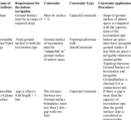
6.1 Locomotion types and their constraints details for subspacing
required slope. space is compared with the capacity
Table 1. Driving locomotion’s constraints (Note. Table is continued from previous column)
Locomotion type: Walking (Walking Person) Geometry representation: 3D cylinder
Note: In addition to constraints of driving locomotion following constraints with variations are added to Walking locomotion
Name of Attribute
Requirement for the indoor navigation
Constraint Constraint Type Constraint application Procedure
CapacityConstraint - Slope of ground surface of indoor
CapacityConstraint - If there is gap is more than the
Locomotion type: Flying (Unmanned Aerial Vehicle) Geometry representation: 3D sphere
Note: In addition to constraints of driving locomotion following constraints with variations are added to Walking locomotion
Name of Attribute
Requirement for the indoor navigation
Constraint Constraint Type Constraint application Procedure
The implementation of whole architecture for subspacing is described in following steps.
6.2 3D building model and storage in IndoorML
The workflow presented in Figure 9 is followed to create the 3D building model and storage in IndoorML. The 3D building modeled in CityGML format is imported into 3D city database in Oracle spatial 11g using CityGML import/export tool. From 3D city database, the 3D model geometries with their semantics data are inserted into IndoorML database in Oracle spatial 11g. Each surface geometry in CityGML with its semantics data is converted into solid space in IndoorML. Room interior surfaces representing interior of room are transformed into room solid representing air space of a room or corridor. Each building installation e.g. stairs, elevators, etc. in CityGML LoD-4 represented as solid is converted into solids representing each
ISPRS Annals of the Photogrammetry, Remote Sensing and Spatial Information Sciences,
planar interior surface of the object (Details about the transformation are skipped due to space constraint). In IndoorML, we have topographic space layer that contains the geometries of space, state, transition, and inter-space connections.
Figure 9: Work flow of 3D building model in CityGML to IndoorML database and subspacing.
6.3 Minkowski sum computation
We start from the navigable space whether it has any adjacent obstacles. If they are then we selected all the obstacle geometries those have the boundary in touch with the navigable space geometry. Then, the boundary surface geometries (boundary geometry touching between two geometries i.e. polygon) are generated between navigable airspace and nonnavigable (obstacle) geometries. Furthermore, these boundary geometries (polygons) are grown to get the Minkowski sum in a direction that must result into valid solids within the navigable geometry. For this purpose, the orientation of participating boundary geometry must be in a way that its normal direction (based on right hand rule) must direct toward navigable geometry. The correction of boundary geometry’s orientation for extrusion is checked through generating a ray in normal direction of boundary geometry and its intersection with the navigable geometry. If the ray is intersecting with navigable space geometry then the orientation of boundary geometry is correct for extrusion otherwise the orientation of boundary surface geometry has to reverse.
In flying vehicle case, the Minkowski sum of boundary geometry (polygon) was computed by replacing vertices with sphere, edges with cylinder and facet extruded in its normal direction to convert in 3D solid. The radius of sphere, cylinder and facet translated distance are equal to that of sphere geometry representing Unmanned Aerial Vehicle locomotion type. When we take the union of these resulting geometries, then we get a geometry that is the Minkowski sum of the boundary polygon obstacle and the locomotion type.
In wheel chair and walking person case, we represented each wheelchair and walking person with a cylinder (3D solid). The Minkowski sum of boundary geometry (polygon) and cylinder was computed by replacing vertices with cylinder, facets are generated by sweeping the extreme edges of cylinder along the edges of boundary geometry (polygon) and facet of polygon are extruded in its normal direction. The translated distance of facet is equal to the extreme furthest point to its centre of cylinder. When we take the union of these resulting geometries then we get a geometry that is the Minkowski sum of the boundary polygon obstacle and the locomotion type (cylinder).
6.4 Operations in IndoorML for subspacing.
We applied constraints given in section 6.1 for different locomotion types on indoor 3D model. The application of these constraints of the locomotion types result into subspaces of indoor 3D model. After performing certain operations (3D summation, subtraction, intersection, etc), the results of 3D building model are visualized in FME (FME) data inspector. During these operations and computations we intensively used ArcObject libraries and tools in Java.
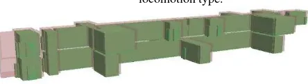
The 3D building model and the result of subspaces are shown in Figures from 10-21. The Figures 19, 20, and 21 show the differences of subspaces according to the different locomotion types for the same 3D building model.
Figure 10.3D semantics building model contains floor, rooms, doors, and stairs geometries.
Figure 11.Building model (state, space, and transition geometries) after subspacing based on conneted
opening spaces.
Figure 12.Opening, conneted opening spaces, state, and transition geometries after subspacing based on
conneted opening spaces.
Figure 13.Obstacle (light maroon color) and navigable (green color) space according to flying locomotion type.
Figure 14.Navigable space according to flying locomotion type (space, state, and transition geometries).
ISPRS Annals of the Photogrammetry, Remote Sensing and Spatial Information Sciences,
Figure 15.Obstacle (light maroon color) and navigable (green color) space according to walking locomotion type.
Figure 16.Navigable space including ground floor space (shown in green color) according to walking
locomotion type.
Figure 17. Obstacle (light maroon color) and navigable (green color) space according to driving locomotion type.
Figure 18.Navigbale space (space, state, and transition geometries) according to driving locomotion type.
Figure 19.Navigable space (state and transition geometries) according to the driving locomotion (Wheelchair)in
IndoorML.
Figure 20.Navigable space (state and transition geometries) according to the walking locomotion (Person).
Figure 21.Navigable space (state and transition geometries) according to the flying locomotion (UAV).
7. CONCLUSION
We addressed the problem of determining 3D navigable subspace for different locomotion types in 3D indoor environments. We proposed a unified architecture to determine
accurate navigable and non-navigable space according to different locomotion types using a static 3D semantic virtual environment represented in an international standard. The network and geometric models of virtual indoor environment were used to determine accurate navigability of space according to the specific locomotion type based on geometric and semantics considerations. The subspacing of indoor space was carried out in a framework i.e. MLSEM. The whole architecture is approximated for simplification and to demonstrate the application of such system. The applied system has some limitations those are as follow.
1. The process of subspacing is based on the assumption that the indoor space cell contains all the information including semantics. But currently available semantic models still have very limited information required for the subspacing. 2. In approximation of geometric models of locomotion
types, we ignored local constraints/ body part movement constraints of a complex system. They have great influence on navigable and nonnavigable space of the locomotion type. They can be dealt with the same procedure we have stated in our paper but it needs specific data structures e.g. LEGO model, to be used to accommodate the micro level representation of navigable and nonnavigable space for the specific locomotion type. The scope of this study does not focus on those constraints and data structures.
Apart from above limitations we did not discuss in detail the computation of obstruction of obstacles, combinations of navigable space cells, transitions between space cells, and transformation of building model from CityGML to IndoorML. We will discuss those issues in detail in future.
8. REFERENCES
Anagnostopoulus, C., Testsos, V., Kikiras, P., and Hadjiefthymiades, S., P., 2005. A Human-Centered Semantic Navigation System for Indoor Environments. In: Proceedings of the International Conference on Pervasive Services, Santorini, Greece. 11-14 July.
Becker, T., Nagel, C., and Kolbe, T., H., 2009. A Multilayered Space-Event Model for navigation in indoor spaces. In J. Lee and S. Zlatanova, editors, Lecture notes in Geoinformation and Cartography, pp. 61-77.
Becker, T., Nagel, C., and Kolbe, T., H., 2009. Supporting contexts for indoor navigation using a Multilayered Space– Event Model. In: Proceedings of the Tenth International Conference on Mobile Data Management: Systems, Services and Middleware, Taipei, Taiwan. May 18-20.
CityGML. Open Geospatial Consortium, Inc. ® (OGC)’s CityGML standard, Version: 3.1.1, OGC Doc. No. 08-007r1, http://www.opengeospatial.org/standards/citygml(16 April 2013).
Diktas, E., D., and Sahiner, A., V., 2006. An object-space method for calculating the Minkowski sums of simple 3D objects. In: Proceedings of the 21th international symposium, Istanbul, Turkey. November 1-3.
Gröger, G., and Plümer, L., 2010. Derivation of 3D Indoor Models by Grammars for Route Planning. In Photogrammetrie- Fernerkundung - Geoinformation, Volume 2010, pp. 191-206(16).
Gröger, G., and Plümer, L., 2011a. Provably correct and complete transaction rules for updating 3D city models. GeoInformatica, Vol. 1 / 1997, Vol. 16 / 2012.
ISPRS Annals of the Photogrammetry, Remote Sensing and Spatial Information Sciences,