Passive filter design for reducing harmonics in light emitting
diode bulb
Rambe Ali Hanafiah1*, Muhammad Safril1, and Suherman Suherman1
1Universitas Sumatera Utara, Electrical Engineering Department, Medan, Indonesia
Abstract. Harmonics reduce power quality and increase inefficiency. Although light emitting diode (LED)
bulb has been considered more efficient than previous bulb technologies; its internal circuits potentially generate additional problems. This paper has surveyed 6 LED bulb samples and measured the harmonics generated by the internal circuits. As a result. 7 Watt type B LED bulb produces the highest 3rd order harmonics current which is incompatible with IEC61000-3-2 Class C. A prototype of LC filter is designed to decrease the harmonic level. The measurement shows that the designed passive filter is able to reduce at least 81.3% of harmonics.
1 Introduction
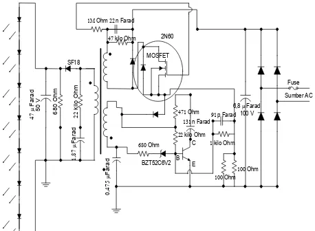
Light emitting diodes (LED) is designed to fulfil the necessity of efficient light bulb as lighting consumes about 20% of total world energy [1][2]. LED bulb is supplied by electricity source through an AC/DC converter, driving light controller circuits [3]. This fly-back circuit as shown in Figure 1, has transformer and capacitor that potentially produce harmonics. The primary coil is to control voltage on fly-back. This bootstrap coil controls the transistor and MOSFET voltages. When starting up. No power produced in bootstrap. Therefore; the start-up regulator such as LR645 and LR8 are employed. After bootstrap produces power, the regulator is off. This fly-back circuit is built in the LED bulb as in Figure 2.
Switching on MOSFET fly-back circuit results electric waveforms which are different from the fundamental one [4]. It results harmonic distortion. Harmonic is defined as a current or a voltage that has frequency folding of its fundamental [5]. These harmonics are unwanted in electrical system. Third harmonic distortion (THDi and THDv) are used to measure harmonic level [6]. In order to comply with IEC61000-3-2 Class C requirement, these harmonics should be reduced. This paper reports harmonic reduction on LED bulb through simulation and implementation.
Fig. 1. Fly-back circuit.
Fig. 2. LED bulb.
2 Research methods
Table 1. Harmonics in LED bulbs.
Parameters LED Bulb 7 watt
A B C D E F
Phase
Voltage (V) 215.12 214.98 226.48 214.73 214.98 223.26
Phase
Current(A) 0.093 0.05 0.038 0.063 0.074 0.147
Power(VA) 18.6 5.7 8.7 7.6 14.4 33.1
Active Power
(W) 7.3 5.5 5.5 7.2 6 5
Reactive
Power(VAR) 17.1 1.5 6.8 2.3 13.1 32.7
Frequency
(Hz) 50.1 50.1 50.1 50.1 50.1 50.1
Power Factor 0.37 0.51 0.63 0.53 0.38 0.15
THDv 1.8 1.7 2 1.8 1.8 2.3
THDi 37.8 154.8 98.5 145.7 44.3 30.1
As shown in Table 1, LED B has the highest THDi 154.8 %. The third order harmonic is 90.3%, the fifth is 76.1%. The 7th, 9th, 11th, 13th and 15th are 58.6%, 42.1%, 31%, 27% and 26%. Based on this fact, the designed filter is intended for overcoming harmonics in LED bulb B.
This research performs simulation and implementation of passive filter design. Simulation is to mimic the real situation. Afterward, L and C values are calculated. In implementation, inductor is designed by using transformer, creating multiple inductor networks.
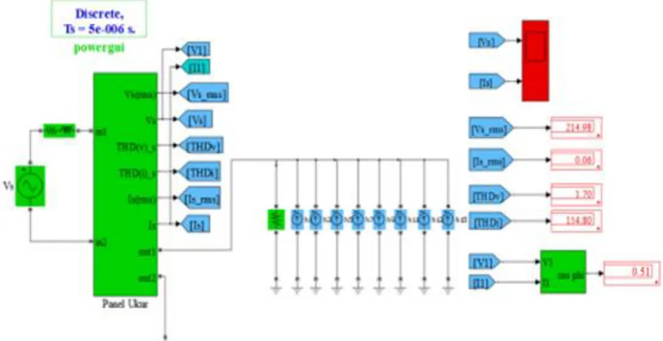
The result is then tested by using either simulation or measurement. Figure 3 shows the snapshots of harmonic values generated by LED bulb B which is used as the
basic of LC filter design. Figure 4 represents the system in simulation.
Fig. 3. Snapshots of LED B Harmonics.
By using data on Figure 3, the load current is calculated by using:
= 0.05 A (1)
The power consumed for power factor 0.51is:
P = 214.98 x 0.05 x 0.51 = 5.48 5.5 watt (2)
If it is assumed that power factor is corrected to 0.98, the load current is:
= 0.026A (3)
The capacitor is calculated by using:
QC= P(tan φawal – tan φtarget) (4)
QC = 5.5(tan 59.34∘ – tan 11.48∘) (5)
QC = 5.5 (1.69 – 0.2) (6)
QC = 5.5 (1.49) = 8.16 VAR (7)
The capacitor value for 8.16 VAR is:
(8)
F= 0.562 F (9)
The inductor is calculated as:
(10)
and:
(11)
Based on harmonics orde:
(12)
Then:
(13)
The inductor (L) is:
(14)
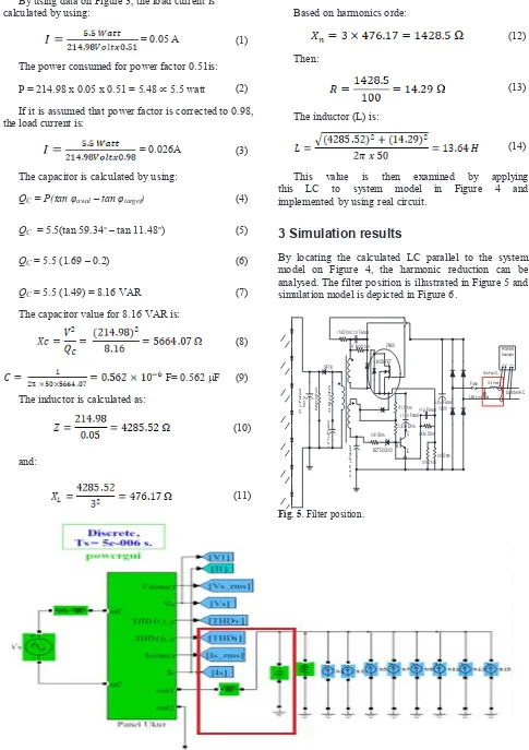
This value is then examined by applying this LC to system model in Figure 4 and implemented by using real circuit.
3 Simulation results
By locating the calculated LC parallel to the system model on Figure 4, the harmonic reduction can be analysed. The filter position is illustrated in Figure 5 and simulation model is depicted in Figure 6.
c c
Fig. 5. Filter position.
* Corresponding author: [email protected]
Simulation shows that the inserted LC filter is able to reduce harmonics values as outline in Table 2.
Table 2. Simulation results.
Parameter Before After
Phase Voltage (V) 214.98 214.97
4 Implementation results
Capacitor is easily found in market. However, inductor is tricky to design. In order to produce 13.64 H inductor, the size and number of turn are calculated as follows:
= 0,95
(15)
h = = 1,43 cm (16)
The surface area is:
Ac = b x h = 0,95 x 1,43 cm2 (17)
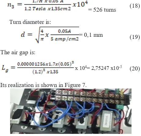
The designed inductor consist of 8 inductor of 1.7 H made of transformer. For each inductor, number of turn is:
= 526 turns (18)
Turn diameter is:
= 0,1 mm (19)
The air gap is:
x 104= 2,75247 x10⁻⁵
(20)
Its realization is shown in Figure 7.
Fig. 7. Filter implementation.
The harmonics value after measuring the implemented filter is shown in Table 3.
Table 2. Simulation results.
Parameter Before After
Phase Voltage (V) 214.98 214.98
The comparison harmonics in LED bulb, simulation with LC filter and measurement with LC filter is shown in Figure 8.
Fig. 8. Performance comparison.
Based on Figure 8, by adding LC filter with C=0.562
μF and L=13.64 H is simulation model, the total current harmonics (THDi) is reduced 91% and average individual harmonic current decreases to 96.3%.
By implementing the LC filter uses capacitor and transformer; THDi decreases THDi up to 89.80% and average individual harmonic current (IHDi) 91 %.
5 Conclusions
References
1. S. Bakhtiar, B., Suherman, Realisasi Sistem Switch Lampu Penerangan Ruangan Otomatis Untuk Meningkatkan Efisiensi Energi Listrik., J. Arus Elektro Indones., vol. 1, no. 2, (2015)
2. E. Mubarakah, N., Al-Hakim, M. Y., Warman, “Energy consumption model on WiMAX subscriber station.(2018, February). Energy consumption model on WiMAX subscriber station. In IOP Conference Series: Materials Science and Engineering (Vol. 309, No. 1, p. 012002). IOP Publishing, Energy Consum. Model WiMAX Subscr. Station. IOP Conf. Ser. Mater. Sci. Eng., vol. 309, no. 1, p. 12002, (2018)
3. W. R. Caberos, A. B., Huang, S. C., Gumera, X. D. G., Liou, Hybrid controller for AC-DC power factor correction converter, in Power Electronics Conference (SPEC), IEEE Annual Southern, pp. 1– 5, (2016)
4. M. Khalilian, H., Farzanehfard, H., Adib, E., Esteki, Analysis of a New Single-Stage Soft-Switching Power-Factor-Correction LED Driver With Low DC-Bus Voltage, IEEE Trans. Ind. Electron., vol. 65, no. 5, p. 3858–3865., (2018) 5. M. H. Gil-de-Castro, A., Rönnberg, S. K., Bollen,
Light intensity variation (flicker) and harmonic emission related to LED lamps, Electr. Power Syst. Res., vol. 146, p. 107–114., 2017.