A model driven approach to model
transformations
Biju Appukuttan
1[email protected]
Tony Clark
2[email protected]
Sreedhar Reddy
3[email protected]
Laurence Tratt
2[email protected]
R. Venkatesh
3[email protected]
1
Tata Consultancy Services, Pune, India. On deputation to Kings College
London.
2
Department of Computer Science, King’s College London, Strand, London,
WC2R 2LS, United Kingdom.
3
Tata Consultancy Services, Pune, India.
Abstract
The OMG’s Model Driven Architecture (MDA) initiative has been the focus of
much attention in both academia and industry, due to its promise of more rapid
and consistent software development through the increased use of models. In order
for MDA to reach its full potential, the ability to manipulate and transform
mod-els – most obviously from the Platform Independent Model (PIM) to the Platform
Specific Models (PSM) – is vital. Recognizing this need, the OMG issued a Request
For Proposals (RFP) largely concerned with finding a suitable mechanism for
trans-forming models. This paper outlines the relevant background material, summarizes
the approach taken by the QVT-Partners (to whom the authors belong), presents
a non-trivial example using the QVT-Partners approach, and finally sketches out
what the future holds for model transformations.
1 Introduction - Transformations and MDA
The OMG Queries/Views/Transformations (QVT) RFP [1] defines the MDA vision thus:
MDA defines an approach to IT system specification that separates the specification of system functionality from the specification of the implementation of that functionality on a specific technology platform, and provides a set of guidelines for structuring specifica-tions expressed as models.
standards... and allows different applications to be integrated by explicitly relating their models.
In less technical terms, MDA aims to allow developers to create systems entirely with models1. Furthermore, MDA envisages systems being comprised of many small, manageable models rather than one gigantic monolithic model. Finally, MDA allows systems to be designed independently of the eventual technologies they will be deployed on; a PIM can then be transformed into a PSM in order to run on a specific platform.
✂✁
☎✄ ☎✆
✝✟✞✠☛✡☞✌✟✍✎✑✏✓✒✕✔✂✖✘✗☞✙✗✖ ✚✛✌☛✜✢✔✟✞✤✣✝✢✏✓✚✦✥✘✧
✝★✞✠✂✡☞✌✟✍✎✑✏✓✒✕✔✂✖✘✗☞✩✗✖ ✚✪✌✂✜☛✔★✞✤✣✝✢✏✫✚✬✥✮✭ ✯✱✰✮✲✳✵✴✮✶✷✸✮✹✱✯✱✺✤✻✮✴✮✼
✽✾✼✰✮✶✿✺✮✲❀❂❁✸✮✻✮✴✤❃✮✴✮✸✤✻✮✴✮✸✤✶ ✯✱✺✮✻✤✴✤✼✕❄✽✾❁✯✱❅
❆✾✸✤✹✮✷✸✤✴✮✴✮✲✷✸✮✹✱✯✱✺✮✻✤✴✮✼
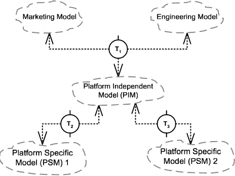
Fig. 1. Transformations and MDA
Figure 1 – based partly on a D’Souza example [2] – shows an overview of a typical usage of MDA. It shows a company horizontally split into multiple departments, each of which has a model of its system. These models can be considered to be views on an overall system PIM. The PIM can be converted into a PSM. In order to realize this vision, there has to be some way to specify the changes that models such as that in figure 1 undergo. The enabling technology is transformations. In figure 1 a transformation T1 integrates the company’s
horizontal definitions into an overall PIM, and a transformation T2 converts the overall
PIM into PSMs, one for each deployment platform.
The following are some representative MDA related uses where transformations are, or could be, involved:
• Converting a model ‘left to right’ and/or ‘right to left’. This is a very common operation
in tools, for example saving a UML model to XML and reading it back in again.
• Abstracting a model. Abstracting away unimportant details, and presenting to the user
only the salient points of the model, is a vital part of MDA.
• Reverse engineering. For example, a tool which recovers Java source code from class files. • Technology migration. This is similar to reverse engineering, but whereas reverse
engineer-ing is simply tryengineer-ing to recover lost information, technology migration is effectively tryengineer-ing to convert outdated systems into current systems. For example, a tool which migrates legacy COBOL code to Java.
Transformations are undoubtedly the key technology in the realization of the MDA vision. They are present explicitly – as in the transformation of a PIM to a PSM – and implicitly – the integration of different system views – throughout MDA.
1 This does not mean that everything must be specified fully or even semi-graphically –
2 QVT
In order for MDA to reach its full potential, the ability to manipulate and transform mod-els is vital. Although there has been much discussion [3,4] of the problem area, as well as attempts at filling this gap in the past [5–8], little practical progress has been made. Recog-nizing the need for a practical solution for transformations, the OMG issued a Request For Proposals (RFP) [1] largely concerned with finding a suitable mechanism for transforming models. This paper is based on the QVT-Partners2 initial submission [9] to the QVT RFP.
3 Fundamental concepts
It is our view that to provide a complete solution to the problem of a practical definition of transformations, the following complimentary parts are necessary:
(1) The ability to express both specifications and implementations of transformations. (2) A mechanism for composing transformations.
(3) Standard pattern matching languages which can be used with declarative and imper-ative transformations.
(4) A complete semantics, which are defined in terms of existing OMG standards.
The solution outlined in this paper can be seen to be chiefly concerned with solving two overarching problems: the need to provide a framework into which different uses of trans-formations can be accommodated, and the need to provide a standard set of languages for expressing transformations. In solving these needs, the solutions to other fundamental requirements as mentioned earlier in this section follow fairly automatically.
4 A definition of transformations
This section outlines the points of our definition of transformations that are most relevant to this paper. See also section 7.
4.1 Framework
We define an overall framework for transformations that allows one to use a variety of dif-ferent transformation styles. This framework also transparently allows transformations to change style throughout the lifetime of a system. Such transparency is enabled by identifi-cation of two distinct sub-types of transformations: relations and mappings.
Relations are multi-directional transformation specifications i.e. they are declarative. In the general case they are non-executable (in the sense of actually transforming a model), but we have identified useful restricted types of bidirectional relations, which can be automatically refined into mappings. Relations are written in any valid UML constraint language, OCL being an obvious example. Typically relations are used in the specification stages of system development.
Mappings are transformation implementations i.e. they are operational. Unlike relations, mappings are potentially uni-directional. Mappings are expressed in the UML Action Se-mantics (AS) and thus encompass all programming language implementations. Mappings
can refine any number of relations, in which case the mapping must be consistent with the relations it refines.
❇
❈ ❉ ❊
❋ ● ❍
■
❏
❑
▲▼▲▼◆❖P◗❘❙❖❚▼❯❙❯
Fig. 2. A high level relation being refined by a directed mapping
Figure 2 shows a relationRrelating two domains. There is also a mappingMwhich refines relation R; since M is directed, it transforms model elements from the right hand domain into the left hand domain.
❱✢❲❳✙❨❩❨ ❬✵❭❳❩❪✵❨❩❫❴✵❭❵✟❳❩❛❜❴✵❪
❝✢❞ ❲❳✙❛❜❴❡❪
❢ ❳❩❣✵❣❡❜❪✵❤
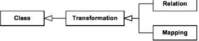
Fig. 3. Transformations, relations and mappings in the MOF hierarchy
Figure 3 shows how transformations, relations and mappings are placed within the MOF [10] hierarchy. AsTransformationis a super-type of RelationandMapping, when we talk about a transformation we effectively mean either a relation or a mapping, we don’t mind which one. When we talk about a mapping, we specifically mean a mapping and only a mapping and similarly for relations. The differentiation between specification and imple-mentation is vital. In many complex applications of transformation technology it is often unfeasible to express a transformation in operational terms. For example, during the initial stages of system development, various choices, which will affect an implementation, may not have been made, and thus it may be undesirable to write an implementation at that stage. Another more general reason for the presence of specifications is that transformation implementations often carry around large amounts of baggage, which whilst vital to the transformations execution, obscure the important aspects of a transformation – by using specifications, these important aspects can be easily highlighted. Nevertheless, implemen-tations are vital for the final delivered system. We also propose a standard operational transformation language to prevent the need to drop to low level technologies such as the XML transformation system XSLT (XSL Transformations) [11] – in order for transforma-tions to be a successful and integral part of MDA, it is essential that they be modelled. Our proposal allows transformations to seamlessly and transparently evolve from specifications to implementations at any point during the development life cycle.
4.2 Pattern Languages
also provide graphical syntax to express patterns, as well as the more conventional textual representation.
5 Transformations
Our definition of transformations comes in two distinct layers. Reusing terminology familiar from the UML2 process, we name these layersinfrastructure andsuperstructure.
5.1 Infrastructure
✐✢❥✵❦❩❧♠♥❩♦✙❧✵♣✮q❩r✵❧♥❩s
t✢✉♥❩❦❩❦
✈✵♠♥❩r✵❦✙✇①✵♠②✟♥✙❧③①❡r
④✢⑤✉♥❩❧③①✵r ⑥✘♥❩⑦✵⑦❡③r✵⑧
⑨✢①✵❧ ✐✢r✵⑩ ❶❷♠
④✢⑤✉♥❩❧③①✵r
✐✢❧❧♠③❥✵❸❡❧⑤
❹✢①❡②✟♥❩③r
⑥❺①❡⑩✵⑤✉❻✤✉⑤✙②✟⑤❩r❡❧
t
①✵r❡❦❩❧♠♥❩③r❡❧
❼
❽✙❾❿➀➁▼➂▼➃➄❿ ➃➅✙➂➀➁▼➂▼➃➄❿
❼
❼
❽▼➅✙➆✢➇❙❾➂❿
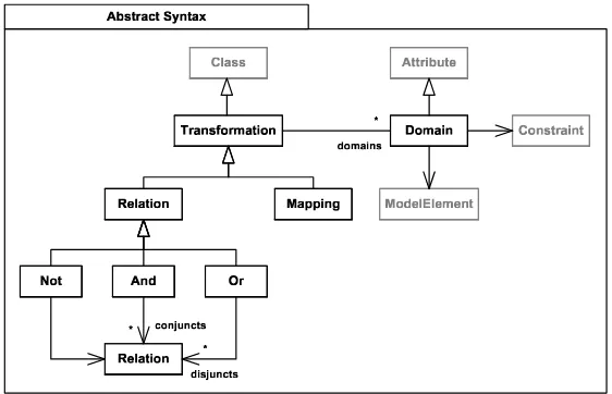
Fig. 4. Infrastructure meta model
Figure 4 shows the infrastructure abstract syntax package. This package can be merged with the standard MOF definition to produce an extended version of MOF. Original MOF elements are shown in grey; our new elements are in black. The infrastructure contains what we consider to be a sensible minimum of machinery necessary to support all types of transformations. The infrastructure is necessarily low-level and not of particular importance to end users of transformations. Its use is a simple semantic core [12].
5.2 Superstructure
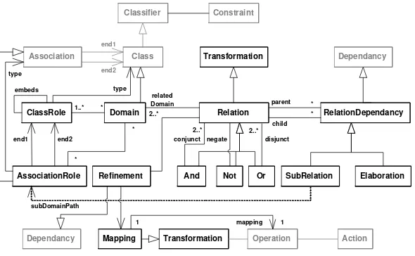
Compared to the infrastructure, the superstructure contains a much higher-level set of transformation types and is suitable for end users. Figure 5 shows a transformation meta-model that extends the transformations meta-meta-model given in Infrastructure. The elements Transformation, Relation, Domain, And, Or and Mapping inherit from and extend the corresponding elements in the infrastructure. Elements from MOF core are shown in gray.
Classifier Constraint
Association Class Transformation Dependancy
ClassRole Domain Relation RelationDependancy
AssociationRole Refinement And Or SubRelation Elaboration
Dependancy Mapping Transformation Operation Action
end1
Fig. 5. Superstructure meta model
5.3 Concrete syntax
Our solution defines a graphical concrete syntax for transformations. Figure 6 lists the most important notations.
Fig. 6. Concrete Syntax for transformations
6 An example
In order to illustrate the salient features of our approach, in this section we present an example between simplified UML models and XML.
6.1 The example model
➡
Fig. 7. The example meta-model
Figure 7 shows a simplified model of UML class diagrams. EachModelElementhas a name; the pathName operation returns a string representing the element’s full pathname. The operation is defined thus:
context ModelElement::pathName(): String if not self.parent then
else
self.parent.pathName() + "." + self.name endif
We assume that all elements have a unique pathname. This can be trivially enforced by placing constraints onPackage andClass to ensure that none of their contents share the same name.
Figure 7 (right hand side) shows a simplified model of XML. We prefix both elements in the model byXMLto avoid having to qualify references via a package name. The model captures the notion of XML elements having a number of attributes, and containing XML elements.
In the rest of this section, we gradually build up a relation from our UML model to XML, from a number of small pieces.
6.2 Building up the transformation
ÝÞß à▼á❙â✢ã☎ä✂å✩æ❩á❙â✢ã
ç✤è✙é❩ê❩è❩ë❡ì
à❙á❙â✢ã☎ä▼íî✩áï❙ðá❙ñ▼ã❙í ò✮ó❺ô❡õ✮öì❩÷✟ì✙ø✵ù
à▼á❙â✢ã☎ä✂úà❙á❙â✢ã❙í ûá❙üý▼ã☎ä✢å✙æ❩á❙â✢ã
ò✮ó❺ô❡þ✢ùùÿ✁✄✂❡ùì
à▼á❙â✢ã☎ä✂ú☎✆✙í ûá❙üý▼ã☎ä✂å✞✝å❙á✟✠✩æ✕á❙â✢ã☛✡☞
ò✮ó❺ô✵þ✢ùùÿ ✁✄✂❡ùì
å ✌
á✟✟✍✎ á✟✟✍✎
Fig. 8. A UML package to XML relation
Figure 8 shows a relation between the UMLPackageand XML using a pattern language. Although at first glance figure 8 may look like a standard UML class diagram, it should rather be thought of as something in between a class diagram and an object diagram. Notice how some attributes in the transformation have constant values given to them, whilst others have variables – each variable name must have the same value across the diagram.
Thus to examine figure 8 in detail, each Package instance is related to an XMLElement
with the namePackage. The XML element has twoXMLAttribute. The first is the name of the package which has a value of pName, thus forcing it to be the same literal name as the UML package. To allow us to reference elements (which is necessary for association ends), we also force each XML element to have a unique identifier – the properties of thepathName operation mean we can use it to produce unique identifiers. An alternative and more general, though more complex, approach to using pathName would be to have a stateful transformation (see section 7.1) which has a counter which is assigned to each element, and maintains a dictionary relating each model element to its unique ID assigned via the counter.
When written in more conventional form, the UML package would be related to the following chunk of XML:
<Package name=pName id=p.pathName()></Package>
The relationsCxEandAxEforClasses andAttributes respectively are much the same as forPxEforPackage.
✏✞✑✒✓
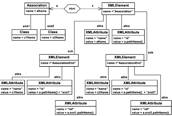
Fig. 9. Transformation of Association
are related, but rather the references themselves. This is where the uniqueidwe have forced onto XML elements comes into play. The UML association is thus related to the following chunk of XML:
<Association name=aName id=asc.pathName()>
<AssociationEnd name=c1Name id=asc.pathName()+"end1"
ref=asc.end1.pathName() />
<AssociationEnd name=c1Name id=asc.pathName()+"end2"
ref=asc.end2.pathName() /> </Association>
6.3 Putting it all together
In this section, we slot the individual relations in the previous sub-section together to form one overall transformation. This creates several new issues that are not present when the relations exist in isolation.
In general, additional constraints will be needed to ensure a relation is completely modelled. For example, a common issue is the need to ensure that all of the contents of an element (e.g. a UML package) are related to a corresponding element (e.g. an XML element). Fig-ure 10 shows how the individual relations in the previous section slot together. Note the inheritance relationships in this figure. The transformation of the abstract ModelElement is captured by the abstract transformationMxE. The information inherited from the abstract ModelElement play a key role in the transformation of the individual elements. Similarly, the individual transformations are derived from the abstract transformationMxEdefined on the ModelElement.
In order to ensure that all of the contents of an element Package are related to a corre-spondingXMLElementthe following ‘round trip’ constraint is needed:
context PxE:
self.p.contains->size() = self.sub->size() and self.p.contains->forAll(m |
❙✵❚✜❯✜❱✜❚✽❲✄❳
Fig. 10. Transformation composition
cxe.m = m))
There are various ways that this constraint can be phrased to achieve the same end result. This particular method makes use of the fact that if the number of contents inp.contains
is the same assuband every element inp.contains has a transformation which is also a member of subthen the round trip is enforced. At the moment the user needs to explicitly enforce this constraint via OCL; we anticipate in the future adding a way to allow the user to specify that the round trip needs to be enforced, without forcing them to write out the entire constraint. The relevant constraint could be trivially generated from a boiler-plate – at the time of writing, unfortunately no OCL equivalent to macros or template programming such as found in [13] exists. We expect this shortcoming to be remedied in the relatively near future.
We now use the example object model in figure 11 to illustrate a complete transformation. This model consists of a package pkg1 which contains two classescls1 and cls2 and an association assoc1 between these two classes. Furthermore, cls1 contains an attribute
attr1.
Fig. 11. Object model example to illustrate transformations
Figure 12 shows the complete relations, which combines several of the preceding relations, such as figure 8 and 10, and a few other similar relations which we do not have space for.
The end result of this transformation is the following XML output:
<Package name="pkg1" id="pkg1"> <Class name="cls1" id="pkg1.cls1">
</Class>
<Class name="cls2" id="pkg1.cls2"> </Class>
<Association name="assoc1" id="pkg1.assoc1">
<AssociationEnd name="cls1" id="pkg1.assoc1.end1" ref="pkg1.cls1" /> <AssociationEnd name="cls2" id="pkg1.assoc1.end2" ref="pkg1.cls2" /> </Association>
Fig. 12. Complete transformation of the example in figure 11
6.4 Mapping
space to write out a complete mapping which refines the relation we have created up until this point, we hope it is fairly trivial to imagine pseudo-code along the following lines which would take in UML and export XML:
function uml_to_xml(model:ModelElement): if type(model) == Package:
xml = XMLElement("Package", id=model.pathName()) for e in model.contains:
xml.append(uml_to_xml(e)) ...
Of course, this operational definition can be given in any programming language e.g. Java, Python or C++.
7 Other features
In this section we outline some other useful features of our definition of transformations.
7.1 Stateful transformations
In many situations, simple transformations, which perform a one step transformation, are not sufficient. Transformations may need to build up large amounts of information whilst in the process of transforming, particularly, if other transformations are involved in the process and may also need to store information over transformations. A simple example of such a transformation is one, which adds to elements a unique identifier based on an incremented counter. Although one could create a new object in the system to track the counter, it is far more natural and less cumbersome for the transformation itself to maintain the counter. To this end, in our proposal all transformations have state by virtue of the fact that Transformation subclasses Class as shown in figure 3.
7.2 Transformation Reuse
In order for transformations to scale up, it is essential to encompass features for reusing existing transformations and composing further transformations from existing ones. Our proposal caters to this requirement in two different ways – transformations can be reused either through the specialization mechanism or by using a more powerful composition mech-anism. A composite transformation is formed of a parent transformation and a number of component transformations which are linked to the parent via logical connectives such as and, etc. The example described in this paper reuses transformations by specializing the
MxEtransformation defined on the ModelElement (figure 10).
8 Conclusions
standard pattern languages for both relations and mappings; stateful transformations; pow-erful mechanisms for reusing transformations and for composing transformations; a succinct definition in two parts utilizing an infrastructure – the simple semantic core, and a super-structure – where the rich end-user constructs exist.
The future for model transformations is hard to precisely predict since it is undoubtedly the case that we are still in the early stages of model transformation technology. We expect approaches such as the one we outline in this paper to be further enhanced and, as real world experience in the area develops, to evolve in different directions. We also expect that in the future specific transformation language variants will be created to handle particular problem domains; nevertheless we feel that most of the fundamental concepts, as outlined in this paper, will hold true no matter the type of transformation involved.
This research was funded by a grant from Tata Consultancy Services.
References
[1] Object Management Group, Request for Proposal: MOF 2.0 Query / Views / Transformations RFP,ad/2002-04-10(2002).
[2] D. DSouza, Model-driven architecture and integration - opportunities and challenges, http://www.kinetium.com/catalysis-org/publications/papers/2001 -mda-reqs-desmond-6.pdf(2001).
[3] J. B´ezivin, From object composition to model transformation with the MDA, in: TOOLS 2001, 2001.
[4] M. A. de Miguel, D. Exertier, S. Salicki, Specification of model transformations based on meta templates, in: J. Bezivin, R. France (Eds.), Workshop in Software Model Engineering, 2002.
[5] K. Lano, J. Bicarregui, Semantics and transformations for UML models, in: J. B´ezivin, P.-A. Muller (Eds.), The Unified Modeling Language, UML’98 - Beyond the Notation. First International Workshop, Mulhouse, France, June 1998, 1998, pp. 97–106.
[6] K. Lano, J. Bicarregui, UML refinement and abstraction transformations, in: Second Workshop on Rigorous Object Orientated Methods: ROOM 2, Bradford, May, 1998., 1998.
[7] W. M. Ho, J.-M. J´ez´equel, A. L. Guennec, F. Pennaneac’h, UMLAUT: An extendible UML transformation framework (1999).
[8] T. Levendovszky, G. Karsai, M. Maroti, A. Ledeczi, H. Charaf, Model reuse with metamodel-based transformations, in: C. Gacek (Ed.), ICSR, Vol. 2319 of Lecture Notes in Computer Science, Springer, 2002.
[9] QVT-Partners initial submission to qvt-rfp,ad/03-03-27(2003).
[10] Object Management Group, Meta Object Facility (MOF) Specification,
formal/00-04-03(2000).
[11] W3C, XSL Transformations (XSLT),http://www.w3.org/TR/xslt(1999).
[12] M. Gogolla, Graph transformations on the UML metamodel, in: J. D. P. Rolim, A. Z. Broder, A. Corradini, R. Gorrieri, R. Heckel, J. Hromkovic, U. Vaccaro, J. B. Wells (Eds.), ICALP Workshop on Graph Transformations and Visual Modeling Techniques, Carleton Scientific, Waterloo, Ontario, Canada, 2000, pp. 359–371.