1/30
COMPOSITE MATERIALS
[Adopsi dari: Zbigniew D Jastrzebski, “The Nature And Properties of Engineering Materials”, John Wiley & Sons, ISBN 0-471-63693-2, 1987, CHAPTER 14.]
Composite materials of various types have been used by mankind since early civilization, for example clay and straw mixture. Nature also creates many materials that like wood are a natural composite consisting of cellulose fibers in a matrix of lignin. In this chapter we will consider as composite materials those that are made of constituents of at least two different types of materials in order to secure the optimum properties. Therefore metals, ceramic glasses, polymers, and cement can be combined in composite materials to produce unique characteristics. Portland cement concrete, asphalt concrete, and similar materials are considered as aggregate composites, whereas reinforced and prestressed concrete can be regarded as a first prototype of modern composite materials. The combination of different materials with a composite system involves different joining processes and operations, for example, welding, brazing, and soldering of metals (see Chapter 8), or a variety of adhesives to join various material systems.
ADHESIVE
An adhesive joint consists of two solid materials (adherends) joined by a thin layer of adhesive. An adhesive can be defined as any substance capable of holding materials together by surface attachment. Adhesives have an advantage over other joining methods in that they can be applied to the surfaces of any material, and materials such as glass and metal, metal and metal, metal and plastics, plastics and plastics, and ceramics and ceramics may be joined together. Structural members joined by adhesives are notably free from any residual stresses. This makes it possible to utilize fully the inherent strength of any material, thus lowering the weight of the whole unit. A serious disadvantage of adhesives is that, because most of them are organic materials, they cannot be used at high temperatures and their strength decreases rapidly as the temperature rises.
14-4 WETTING AND BONDING
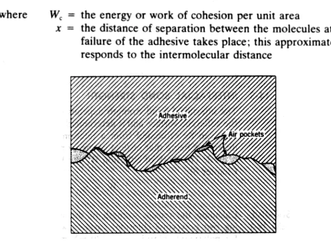
As discussed in Chapter 6, adhesion is high between materials of high surface energy, since this will make it more difficult for a junction to be broken. Since real solid surfaces have many irregularities, a true surface area is many times greater than the apparent surface area and, subsequently, the work of adhesion should be much higher than that estimated for the apparent area. The main difficulty, however. is in filling completely all pores in the adherend surface so that there will be no air pockets or voids left between the solid surface and adhesive (Fig. 14-1). To accomplish this, the liquid adhesive must penetrate all pores and crevices, eliminating the air pockets so that a homogeneous bond between the adherend and the adhesive results. For good wetting the contact angle O between the liquid adhesive and the solid adherend should be as small as possible and the viscosity of the adhesive during application should be low to make it flow easily into the pores and crevices. As the contact angle increases, wetting decreases and the tendency toward the development of air pockets at the adhesive—adherend interface increases. These air pockets serve as stress concentration raisers adversely affecting the strength of the interfacial bond between the adhesive and the adherend surface.
14-2 COHESIVE BOND STRENGTH
2/30
by the adhesive is achieved, the intermolecular forces at the interface are sufficiently strong so that failure occurs within the adhesive instead of at the adhesive—adherend interface. Then the strength of an adhesive joint will be that of the cohesive bond strength of the adhesive itself. This cohesive bond strength can be determined from the relation
FIGURE 144 Possible surface defects during application of an adhesive.
Since the work of cohesion is given by W, = 2y1 (see Equation 6-6) Equation 14-1 can be written
For example, if we take polystyrene as an adhesive with a surface tension of 33 mN/m and assume the intermolecular distance x = 0.5 nm (5 Å), we get
which is the maximum theoretical cohesive strength of the adhesive. Usually the cohesive strength of real adhesives is much lower because of internal stresses, cracks, and flaws within the bulk of the adhesive. These may arise during application and subsequent solidification of the adhesive as the result of differences in coefficients of thermal expansion between the adhesive and the adherend.
14-3 INTERFACIAL BOND STRENGTH
3/30
Illustrative Problem 14-1
This result indicates that in the case of complete wetting of the substrate by an adhesive, the shear strength of the interfacial bond exceeds that of the cohesive strength of the bulk adhesive. Thus, if the adhesive is properly applied, failure will occur within the bulk of the adhesive instead of at the adhesive—adherend interface. For this reason thin layers of adhesives, as long as they sufficiently cover the interfaces, provide stronger rather than thicker joints. Furthermore, the effect of any shrinkage or expansion of the adhesive is reduced, since the forces exerted by a thin adhesive layer are considerably smaller than those of a thick layer.
The interfacial shear strength of an adhesive joint can be increased further by decreasing the contact angle and increasing the magnitude of intermolecular forces between the adhesive and the adherend surface. These can be achieved by modifying the surface characteristics of the adherend or lowering the interfacial surface tension. The latter can be accomplished by adding special surface active agents to the liquid adhesive before its application. The surface characteristics of the adherend can be modified by special surface activation methods such as electric discharge or etching in oxidizing acids. This results in polar hydrogen bonding sites on the nonpolar surfaces, thereby increasing the surface tension of the adherend solid, improving its wettability, and increasing the bond strength of the adhesive joint. Frequently, the surface of the adherend is roughened to increase the adhesion. Roughened surfaces, in addition to the increased true surface area, provide a mechanical bonding because of the edging and interlocking of the adhesive among the surface crevices. This advantage is fully realized only as long as there is no increase in the number of gas pockets or voids in the surface depressions of the adheend. External moisture and the solvent vapor can slowly work their way into such a bond interface displacing the adhesive from the surface. Moisture and oxygen are the classic displacing agents and may cause swelling of the adhesive, the adherend, or both. This with resulting stresses may lead to bond failure. The durability of the metal—polymer bond depends to a great extent on the stabliity of the surface oxide on the metal. For example, in an aluminum—adhesive bond the penetration of moisture into the polymer—metal interface causes the surface oxide on the metal to convert to hydroxide. This results in loss of adherence and considerably reduces the strength of the bond giving rise to the adherend failure. This reaction is highly dependent on temperature, moisture content, and permeability of the polymer—adhesive to water and oxygen.
4/30
Adhesives of different shear moduli and having different cure temperatures can be used to modify the effects of differences in coefficients of thermal expansion of the adherends, thereby reducing thermal shear stresses.
WOOD
14-4 STRUCTURE OF WOOD
5/30
Hemiceliuloses are polymers of anhydrosugar units and together with lignin, which is a three-dimensional amorphous polymer of phenolic substances, form the matrix in which the cellulose chains are embedded. The cellulose molecules are held together by hydrogen bonds in both crystalline and amorphous regions (Fig. 14-3). In the crystalline regions hydrogen bonds are highly regular whereas in amorphous regions they are completely irregular. Two hydrogen bonds per each glucose unit contribute to the crystalline regions as intermolecular bonds between the adjacent cellulose units. The third hydrogen bond is intramolecular between two adjacent units with the same molecule. Numerous hydrogen bonds (about 19 kJ/mol for the bond) per cellulose molecule account for very strong intermolecular forces between the chains exceeding greatly the strength of the intramolecular bond within the chain. This accounts for the high rigidity and crystallinity of the wood cell structure, preventing it from melting and dissolving.
6/30
14-5 PROPERTIES OF WOODWood is not a continuous solid body but contains many voids in the form of longitudinal vessels called cavity cells as well as accidental cracks and fissures in the cell wall. The ratio of these voids to the total volume of the cell largely determines the density of the gross wood. The density of the wood substance is approximately constant, about 1560 kg/rn3 (1.56 g/cm3), in all species, but the bulk density is much lower and varies
considerably for different types of wood. For example, the density of balsa is 120 kg/rn3 (0.12 g/cm3) and that of oak is 740 kg/m3 (0.74 g/cm3) whereas the density of an
exceptionally heavy wood such as blackwood is 960 kg/m3 (0.96 g/cm3) and that of
ironwood is 1080 kg/rn3 (1.08 g/cm3).
The cell wall is highly hygroscopic because its main constituent cellulose contains numerous hydroxyl groups that are strongly hydrophilic. When exposed to moisture, the cell walls absorb large amounts of water and swell. This process considerably reduces the rigidity of wood and causes its dimensional instability. The effect of the absorbed water molecules, like that of a plasticizer, is to neutralize the intermolecular forces between the cellulose macromolecules, increasing the plasticity of the wood and reducing its strength.
Fiber Saturation Point. Variations in the moisture content of the wood with atmospheric conditions result in dimensional changes such as sweLling and shrinking. Wood shrinks and swells considerably more in the transverse direction than in the longitudinal one. Transverse shrinking and swelling is 10—15%, whereas in the longitudinal direction it is about 0.1%. The two main reasons for such a high degree of anisotropy of the wood are cell distribution and microfibril orientation. To prevent excessive shrinkage or swelling, the wood is seasoned before it is put into service. Seasoning minimizes the effect of subsequent moisture variations by adjusting the water content of the wood as nearly as possible to what would be obtained at the equilibrium conditions under exposure to average atmospheric conditions.
7/30
into three groups: coal tar derivatives, waterborne preservatives, and chemicals soluble in volatile oils and organic solvents.
14-6 WOOD PRODUCTS
Wood is an important structural material but, because of its high anisotropy and hygroscopic properties, it has certain limitations. Various methods are used to improve the dimensional stability or strength of wood when exposed to the atmosphere while in service. These methods have resulted in the development of such commercially important forms of modified wood as impreg, compreg, and plywood.
Impreg is made by impregnating thin sheets of wood veneer with a phenolic resin so that the cell cavities are filled and bonded together with resin, which is then cured at a temperature of 150 to 160°C (300 to 320°F) to produce crosslinks. Treated veneers are usually assembled together and glued with the same resin. Compreg is also made by impregnating veneer wood with resin, but the curing takes place under pressure sufficient to compress most species of wood to a specific gravity of 1.30 to 1.35. This makes compreg much stronger than impreg. Both treatments greatly increase the chemical resistance, decay resistance, electrical resistance, and dimensional stability of
the wood.
Plywood is made by bonding together an odd number of thin sheets of wood 0.5 to 12 mm thick (0.02 to 0.5 in.) with the grain of alternate sheets perpendicular to each other and bonded together by phenolic resin. The main purpose is to overcome the directional properties of wood and to obtain a material more uniform in all directions. The dimensional stability is only slightly improved.
A wood—plastic composite is produced by impregnating a natural untreated wood with a liquid monomer such as methyl methacrylate, acrylonitrile, or styrene, followed by polymerization induced by ionizing radiation. The resultant material is much harder than the original wood and has much greater compressive strength and abrasion resistance, showing greatly improved dimensional stability because of low moisture absorption. It also exhibits improved shear and static bending strength but retains natural woodgrain and color.
CONCRETE
Concrete is a building and structural material obtained by mixing cement, a mineral aggregate, and water in suitable proportions so that the result is a plastic and workable mass that can be molded into any desired shape. Concrete is one of the most important materials of construction, and it ranks second only to steel in its many different industrial applications.
The quality of concrete depends on the properties of the materials used, the methods of batching and mixing, and the methods of construction. The basic materials of concrete are cement, mineral aggregate, and water. Some admixtures and agents can also be added to the concrete mix to enhance certain desired properties, but they are not considered to be concrete materials in the proper sense.
14-7 DESIGN OF CONCRETE MIXES
The design of concrete mixes determines the most economical and practicable combination of aggregate. cement, and water that will produce a concrete of required workability, strength, and durability under specific service conditions.
8/30
ingredients by arbitrarily selected volumes, for example, one volume of cement to two volumes of sand and four volumes of crushed stone or gravel.
Mixes with cement—sand—gravel volume proportions of 1:1.5:3, 1:2:4, and 1:3:5 have been widely used. Experience indicates, however, that except for cement-rich mixtures, a still larger proportion of sand is necessary to obtain the desired workability. Hence most of the mixtures now used show cement— sand—gravel proportions of 1:2:3.5, 1:2.5:4, and 1:3:5. The amount of water added is estimated by eye alone to produce the required workability for any particular application.
Design methods for concrete mixes are based on two basic principles: the water—cement ratio and the absolute-volume principle. The absolute-volume principle states that a unit volume of concrete is the sum of the absolute volumes of its components. Additional factors, such as the aggregate grading, the size and shape of the particles, the surface characteristics of the aggregate. and the cement—aggregate ratio, are also considered. The water—cement (W/C) ratio is the ratio of the weight of water used to the weight of cement in any given mix; it can also be expressed as milliliters of water per one kilogram of cement. The water-cement ratio represents the water necessary for the hydration of the cement compounds (see section 9-10), for lubrication of the particles of the mix, and for making up evaporation and other losses during mixing and placing of the concrete. For concretes having a compressive strength less than 41 MPa (6000 psi), the W/C ratio controls mainly the strength of concrete because the cement paste is usually much weaker than mineral aggregate. If the W/C ratio falls below 0.5 had compaction becomes difficult; for such mixes the strength of concrete is dependent both on the W/C ratio and on the strength, shape, and proportion of various aggregate particles.
Illustrative problem 14-2 shows a typical calculation used in the design of a concrete mix.
10/30
Only the free surface moisture is subtracted from the amount of water initially calculated because the absorption moisture does not add to the mixing water of the concrete. 1f this correction for moisture were not made, the total water in the mix would be
165 + 24.0 + 5.84 = 194.8 kg or 194.8 liter or 39.4 gal/yd3
raising the W/C ratio to a value of 0.68. This corresponds to concrete with a compressive strength of 18.6 MPa (2700 psi).
If the concrete contains entrained air, in the calculation of the proportions of concrete ingredients. the amount of air in cubic meters must be added. Thus 1 m3 (or 1 yd3) of
11/30
and gravel, plus the volume of the entrained air. Apart from its many advantages as a material of construction, concrete has certain limitations and disadvantages. These are its low tensile strength, which is 10 or 15 times smaller than the compressive strength, shrinkage and expansion, thermal volume changes, and permeability. These deficiencies can be prevented or considerably reduced by using reinforced concrete, mechan ical prestressing, or special additives during mixing fresh concrete. Recently various concrete—polymer combinations have been used to produce the materials with greatly improved strength and durability that can be used for a variety of important industrial applications such as nuclear reactors, highways, pipes, storage tanks, and many others.
14-8 ASPHALT CONCRETE
Asphalt concrete is competitive with cement concrete for use in construction of highways, roadbeds, and other surfaces. Asphalt concrete is made by mixing a suitably graded hot aggregate produced from crushed rock with asphalt cement. The terms asphalt, asphaltic bitumen, and bitumen are generally synonymous. Asphalt is a black to dark brown solid or semisolid material consisting predominantly of mixtures of hydrocarbons that are completely soluble in carbon disulfide. Asphalt is a thermoplastic material and it softens on heating and hardens on cooling. The viscosity—temperature relationship of asphalt is a very important factor determining its properties and suitability for many applications. Because of its chemical nature, asphalt is resistant to most nonoxidizing acids and corrosive salts, but it is attacked by concentrated sulfuric acid and is soluble in many organic solvents.
Asphalts are processed to asphalt cements, liquid asphalt products known as cutbacks, and asphalt emulsions. Asphalt cements are solid or semisolid products and require heating to convert them into a fluid state before application. Cutbacks are solutions of asphalt cement in organic solvents such as kerosene, naphtha, gasoline, and others. Depending on the amounts of solvents and their boiling pomts they are divided in rapid curing, medium curing, and slow curing products. Emulsified asphalts find numerous applications in small repair jobs on pavements especially when the road surface is wet.
12/30
Cutback asphalts of suitable consistency can be mixed with a crushed rock aggregate and applied and rolled at room temperature. The surface hardens after a certain amount of solvents evaporates. Products can also be spread hot over well-prepared road surfaces and subsequently covered by a layer of crushed rocks of suitable grading and then compacted. Such asphalt pavements perform well only under light traffic and are mainly used for small jobs or for temporary road surfacing.
Emulsified asphalt is also sometimes used for small repair jobs, mainly patching, especially when the road surface is wet. An asphalt emulsion is mixed on the spot with suitable graded aggregate and placed in holes and compacted. After the emulsion breaks down, the resultant patch is pretty strong and weather resistant.
About 70% of all asphalt products are used as asphalt cements, 15% as cutback asphalts, and the remainder as asphalt emulsions (9%) and road oils (6%).
14-9 REINFORCED CONCRETE
Reinforced and prestressed concrete can be considered as the prototypes of modern composite materials. Concrete is a heterogeneous material characterized by a high compressive strength (average quality concrete 28 MPa (4000 psi)1 but a low tensile strength that is 10 or 15 times smaller than the compressive strength. When a concrete member is bent, failure occurs on the tension side of the member, resulting in cracks in the concrete mass. To overcome this weakness, reinforced concrete has been designed in which steel in the form of rods, wires, bars, or fabric is embedded in the fresh concrete. This minimizes the development of tensile stresses in concrete and produces material of much greater strength in compression. shear, and tension. In a reinforced concrete, steel bars or rods carry the tensile stresses that the concrete so poorly resists. The relationship between the stresses in the steel reinforcement and the surrounding hardened concrete corresponds to the ratio of their respective moduli of elasticity in tension called the modular ratio, m = Es/EC. Here the terms Es and EC denote the Young moduli for steel
and concrete, respectively. Frequently, the value of the effective modulus of elasticity of concrete, EC’, is used, which is defined by
It is obvious from Equation 14-4 that E’ is smaller than EC; it is usually about 14 GPa (2
X 106 psi) whereas EC is about 28 GPa (4 X 10⁶ psi).
It can be easily shown that if the tensile stress in the reinforcement (steel rods) exceeds the value of the compressive strength of concrete (e.g., 28 MPa), the concrete surrounding the reinforcement will develop tensile cracks. For example, assume the applied tensile stress on the slab of reinforced concrete is 70 MPa (10,000 psi); then the tensile strain developed in the steel rod reinforcement will be
13/30
E = 28 GPa (4 X 10⁶ psi), then the ultimate tensile strain of concrete will
Hence the externally applied stress of 70 MPa (10,000 psi), although much below the tensile strength of the steel, will result in cracking of concrete surrounding the reinforcement. Thus, if the concrete is not to crack in tension, the stress in the reinforcement (steel) should be below 28 MPa (4000 psi). For many applications cracking in the tensile zone is not detrimental to the general behavior of the member, since the bond between steel and concrete is sufficiently high to prevent the width of the cracks from becoming significant. However, if the width of the cracks is excessive, then concrete may become too permeable to moisture and gases, and corrosion of the steel reinforcement may occur.
Steel is well suited as the reinforcement for concrete because its coefficient of thermal expansion is close to that of concrete, the adhesive bond between the interface steel— cement paste is very strong, and the steel is protected from corrosion by the highly alkaline environment (pH about 12) of the cement paste. The adhesion of steel to the cement paste can be improved still further by imparting to the reinforced rods special surface patterns that provide for better interlocking between the cement paste and the steel surface. Reinforced concrete can also be produced by incorporating fibers with high modulus of elasticity, high tensile strength, and high elongation at fracture. Asbestos and glass fibers, as well as some organic fibers such as cotton, rayon, and polyester, are susceptible to deterioration by alkalies. However, nylon, propylene, and polyethylene have a good resistance.
14-10 PRESTRESSED CONCRETE
Reinforced concrete usually cracks in the tensile regions when subjected to a relatively small fraction of the working load. To make a better use for structural members, prestressed concrete has been designed. The prestressed concrete involves the introduction of an internal compressive stress into a structure. Thus cracking is no longer inevitable in a concrete structure, and this fact alone makes the material much more resistant to chemical attacks. Prestressed concrete is usually designed so that the tensile cracks may develop only at some load greater than the working load. With prestressed concrete the prestressing force may be varied as desired within a wide range. Before any tensile stress occurs in the prestressed concrete, the preapplied compressive stresses first must be counteracted or wiped out.
The precompression is usually obtained by two main methods: pretensioning and postensioning. In pretensioning, the prestressing force is applied by means of high-strength steel wires called tendons, which are arranged end to end between two fixed anchorages. Tendons are then stretched to a high state of stress and the molds are filled with fresh concrete. After the concrete has hardened, the tendons are released from the anchorages and the concrete is then put into compression because these tendons contract. The stress in tendons is transferred to the concrete by bond stress; the full effect of prestressing, however, is realized only at certain distances from the ends of each member, called transmission zones.
14/30
Steel tendons are most widely used for prestressing. They should be made of high-strength steels with an ultimate high-strength of over 830 MPa (120,000 psi). Since such steels are highly elastic, the elastic strain during stressing is more than six times that of mild steel. The steel tendons are usually stressed to about 70% of their ultimate strength during the prestressing operation. The concrete used for prestressing should be of high quality, having a compressive strength between 41 and 55 MPa (5946 and 7977 psi) and low shrinkage and creep rate.
Prestressed concrete is widely used in highway and railway bridges using precast, pretensioned units for spans up to 15 m (50 ft); for longer spans posttensioned construction is used. Many vessels and tanks are being prestressed by passing tendons around them and thereby applying a uniform precompression to the vessel’s walls. The wires that are located outside of the tank walls are coated for protection. Vertical prestress is also used in prestressed concrete pipes.
14-11 CONCRETE—POLYMER COMPOSITES
The introduction of polymeric materials into concrete is rapidly expanding. There are three main classes of concrete—polymer composites: polymer impregnated concrete, polymer cement concrete, and polymer concrete in various modifications.
Polymer Impregnated Concrete (PIC). Polymer impregnated concrete involves incorporation of a suitable monomer into the pore structure of a preformed cured concrete or mortar and subsequent in situ polymerization either by free radical mechanism or by heat and pressure. Polymers may be incorporated in three ways: (1) by adding a polymerizable monomer to a fresh concrete or mortar mix, and then curing both concrete and monomer (polymer), (2) by adding a latex into a fresh cement or concrete mix and then curing the composition in the presence of polymer, and (3) by impregnating a crude mortar or concrete with a monomer using thermal or radiation catalysts.
Impregnation of mortars with monomers involves preparation of mortar by mixing cement with sand (1:3 by weight) and using a high water/cement ratio of 0.7 which after curing gives a much more porous material that favors the penetration of monomer into the mortar. Then the material is dried and heated in the autoclave under pressure to produce the polymer impregnated cement mortar. The product is a typical composite material where both matrix and filler materials are continuous and interconnected phases. Polymer impregnation of mortars, concrete, and porous ceramics can result in major improvements in mechanical strength, elastic modulus, and impact resistance. It appears that the mechanism for reinforcement in PIC is the ability of a polymer to act as a continuous, randomly oriented reinforcing network, to increase the strength of the cement—aggregate bond, to repair microcracks and increased resistance to crack propagation, to absorb energy during the deformation, to reinforce the micropores, and to bond with the cement phase.
15/30
densification of the cement gel structure and good bonding between the cement and aggregate surfaces and within the hardened cement paste.
Precast Polymer Concrete. A pure quality of silica sand of the size 30—40 mesh is mixed with a polymeric binder such as epoxy, methyl methacrylate, and polyesters. Usually these resins are used as monomers which after mixing with the sand and casting are polymerized either by heat or by radiation. The product has much improved properties compared to Portland cement combinations but the price is at least seven times higher. As resins, polyesters are most widely used because of their lower cost and good overall properties. To improve the properties a specific amount of glass fibers can be mixed, as well as a coupling agent such as silane to promote wetting and adhesion of silica sand and the polymer. Another formulation can be used to precast or filled-installed corrosion-resistant applications including floor tiles, floor toppings, pump bases, pipes, and similar, by using a furan polymer concrete which is two to five times stronger than Portland cement concrete and is resistant to acids, salts, solvents, and alkalies. Furan resins are thermosetting polymers obtained by condensation polymerization of furfural and furfuryl alcohol. The latter are mixed with graded silica aggregate and cured with an acidic base catalyst.
Manufacture of High-Strength Concrete. High-strength concrete is produced from properly sized active mineral aggregates using special surface active agents to reduce the amount of water necessary for adequate workability of the fresh mix (W/C ratio from 0.27 to 0.32), curing at 20°C (68°F) and 80—90% relative humidity for 24 h, and immediately placing the mix in an autoclave at 100°C (360°F) and 1.01 GPa (10 atm.) pressure. Then the mix is heat treated at 200°C (400°F) for another 24 h. The heat-treated specimen is evacuated to 133 Pa (1 mm Hg) at ambient temperature for 1 h and soaked in a styrene or other monomer with curing agents, coupling agents, and catalysts for 9 h for impregnation. Then the specimen is placed in hot water at 80°C (160°F) for an appropriate time to complete polymerization, and allowed to cool. The compressive strength of such specimens was 196 MPa (28.5 bi) for a W/C ratio of 0.32 and 235 MPa (34 ksi) for a W/C ratio of 0.27.
14-12 OTHER CEMENT-BASE COMPOSITES
Portland cement because of its overall good characteristics, relatively low price, and ready availability offers great potential for use as composites with various fiber and particulate matters both organic and inorganic.
Wood-Cement Composites. Wood—cement composites are obtained by mixing large quantities of cement with wood particles and water usually in the following proportions by weight: 60% cement, 20% wood particles, and 20% water. Small quantities of chemicals are added to cause proper wetting of the wood and to accelerate setting and hardening of the cement. The properties of the final product depend on their density determined mainly by composition.
Fiber-Reinforced Cements. Cement offers great potential for fiber strengthening due to its low modulus. It has been shown that significant strengthening and increased work of fracture may be achieved by utilizing a variety of reinforcements such as metal wires, glass fibers, asbestos and carbon fibers, and alumina fibers. The fibers limit the length of cracks during the early stages of initiation from preexisting flaws due to the fibers ahead of the crack tip opposing elastic displacement of the matrix.
16/30
aggregates, in this order, are charged into the mixer in the usual manner. Dry mixing is carried out for 1 min; then water is added to the rotating mix and the drum is rotated for another 30 s.
Steel fibers have also been used in polymer-modified concrete. A fracture mode depends markedly on the interface bond strength between fiber and matrix. Steel fiber-reinforced refractory concrete has also been increasingly used by monolithic refractories extending their service life through the use of steel fibers. The effectiveness of the reinforcement depends on the amount of fibers, fiber aspect ratio, and fiber properties such as yield strength, corrosion resistance and oxidation resistance, and the service environment. For lower temperatures carbon steel can be used but with increasing temperatures stainless steels, and super alloys can be required.
ADVANCED COMPOSITE MATERIALS
Advanced composites are usually combinations of a matrix or binder materials and some kind of reinforcement. An effective method to increase the strength and to improve overall properties is to incorporate finely dispersed phases into the matrix, which can be metal, ceramic, or plastic. These dispersed phases may be either precipitate and/or particulate matter, or fibers and whiskers of great variety in size dimensions and characteristics.
14.13 DISPERSION-STRENGTHENED COMPOSITES
Materials can be strengthened by dispersing particles of a second phase in them. Thus metals containing finely dispersed particles are much stronger than the pure metal matrix, and polymeric materials become much stiffer. The presence of finely distributed hard particles increases the elastic limit because particles perturb the flow pattern of the stress deformations, causing rapid hardening. The effect depends on the particles’ size, shape, concentrations, and physical characteristics. Accordingly, two main types of strength ening can be distinguished: dispersion strengthening and particulate strengthening.
Dispersion strengthening carried out in metallic systems is achieved by dispersing a hard, inert phase of submicrometer size in metallic matrix. This phase may be metallic, intermetallic, or nonmetallic, but oxides are most frequently used because of their inertness, hardness, and high thermal stability. The strengthening mechanism occurs because very fine particles below 0.1 µm form effective obstacles to dislocation movements, which must cut through the particles or take a path around them. For effective strengthening spacing of the particles must be less than 0.1 µm. Dispersion strengthening has an advantage over precipitation hardening because the hard, dispersed particles function as dislocation obstacles at the high temperatures at which the strengthening effect of the precipitation in age-hard-enable alloys disappears. Examples of dispersion-strengthened metallic systems are aluminum—aluminum oxide system, referred to as SAP having the dispersed particles of Al2O3 of 0.1 to 0.2 µm, and nickel—
3 vol % thoria (ThO2), known as TD nickel (see Chapter 8).
17/30
more effective than ceramic dispersion. If the crack meets an obstacle it tends to bow between the particles, consequently increasing the crack propagation stress.
14-14 PARTICULATE-STRENGTHENED SYSTEMS
The difference between particulate composites and dispersion-strengthened composites is in the size of the dispersed particles and their volumetric concentration. The particles are 1 i.am or more and of concentrations of 20 to 40 vol%. Because of their size, the particle cannot interfere with dislocations and exhibits a strengthening effect by hydrostatically restraining the movement of matrix close to it. The zone of influence of restraint around each particle can overlap or interact with another particle only over a very limited area. It is therefore very important that the particles should be small, properly distributed, and of uniform size. The optimum interaction of the particles as reinforcement occurs when the particles are nearly identical in size. The composite elastic modulus of a particulate reinforced composite follows the “rule of mixture’s law”: it falls between the upper value
and lower value
Particulate composites are made mainly by powder metallurgy techniques that may involve solid or liquid state sintering or even impregnation by molten metal. Examples are the tungsten—nickel—iron system obtained as a liquid sintered composite, and the tungsten—nickel--copper system.
In viscous polymeric and related systems the use of particulate matter, called fillers, is widespread. Filler particles cause stiffening of the polymeric matrix, control the coefficient of thermal expansion, improve heat resistance, creep and the strength and impact resistance, modify rheological properties, and lower the cost of the material. As filler particles, fine powders of spherical or angular shapes, fine flakes or needlelike particles, and fine fibers such as asbestos or similar materials of a relatively wide range of particle sizes are used. The improvement in properties depends on the properties of the filler, the size of its particles, and their surface characteristics. Here, we would have to distinguish between volume effect fillers and surface effect fillers. Fillers that predominantly exhibit volume effect phenomena and exhibit surface effects only to a small extent are called inactive fillers. The degree to which these fillers enhance the stiffness can be given by the relation:
and, since
we can write
Gm and ηm denote the values of the shear modulus and the viscosity of pure
18/30
Fillers exhibiting a high degree of surface phenomena in addition to the volume effect cause a much greater increase in strength and stiffness than that predicted by Equation 14-7. For example, the unique role of carbon black as a reinforcing filler in the rubber system is due to its strong surface adsorption characteristics.
14-15 FIBER-REINFORCED COMPOSITES
The most important fiber-reinforced composites are those produced by using fibers or fine whiskers. As a matrix, there may be a metal or alloy, plastic, or ceramic. Fibers may also be metals, ceramics, or plastics. A significant strengthening of the system will occur only if the elastic modulus of the fiber is greater than that of the matrix, and if the tensile stress can be transmitted to the fibers. If fibers of lower modulus than the matrix are used the ultimate strength of the composite will be reduced because the matrix rather than the fibers will carry a greater proportion of the applied load. Stresses may be transmitted to the fibers by plastic or elastic deformation of the matrix. For discontinuous fibers reinforcement the ultimate strength of the fiber can be realized only if it lies parallel to the tensile axis. The matrix binds the fibers together and protects them from mechanical and chemical damage that might occur by abrasion of their surfaces or by chemical attack of some extraneous matter. Furthermore, the matrix separates the individual fibers and prevents a brittle crack that passes completely across a section of the composite. The strength of the fiber-reinforced composites is determined by the strength of the fibers and by the strength and nature of the bond between the fibers and the matrix. The matrix serves as a medium that transfers and distributes the load to the fibers. The bond between the fiber and the matrix must be strong enough to prevent interfacial separation or fiber pullout under the external loads. There should be no extensive chemical reaction that weakens the fibers between the fibers and the matrix.
Two types of fiber reinforcement are used: continuous fibers and discontinuous fibers.
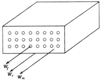
Continuous Fibers. For continuous fiber reinforcement the strain in the matrix and the strain in the fiber under a load are initially the same. At low stresses we can assume that both fiber and matrix deform elastically but, with increasing stress, the matrix may deform plastically while the fiber still will be elastic. For unidirectional composites of continuous fibers the strength and the modulus of the composite can be estimated from the following analysis (Fig. 14-6). Let us assume that all fibers are identical and are unidirectional, extending throughout the composite, and that no slippage is permitted at the interface. The strain of the composite must be equal to that of the fiber and of the matrix. The load Wc on the composite will be then carried by the fibers Wf and by the
matrix Wm, so that
Since the load W = σA, the corresponding stresses σc, σf, and σm, acting on the
respective cross-sectional areas Ac, Af, and Am, will give
19/30
FIGURE 14-6 Distribution of loads for a continuous fiber reinforcement composite.
20/30
SolutionTransverse Loading. Tensile failure at 900 to the filament direction occurs at very low stresses approximately half of the resin strength. This appears to be the effect of stress concentrations at the fiber—resin interfaces. To counteract this, so-called cross-plied laminates are made having alternate orientations of fiber rotated by 900. A more isotropic composite would result if 45 plies were also inserted in the alternate arrangement (Fig. 14-7).
Let us consider the composite, which has three plies oriented parallel to the load and eight plies normal to the load. If the load is applied perpendicular to the fibers’ longitudinal direction, the matrix is then free to deform, so the presence of fibers exerts a relatively small effect. The stress is constant and the strains on individual phases are different because they act independently. Then the total deformation will be equal to the sum of the deformations of the fibers and the matrix
Transverse Loading
.
Tensile failure at 900 to the filament direction occurs at very low stresses approximately half of the resin strength. This appears to be the effect of stress concentrations at the fiber—resin interfaces. To counteract this, so-called cross-plied laminates are made having alternate orientations of fiber rotated by 900. A more isotropic composite would result if 45 plies were also inserted in the alternate arrangement (Fig. 14-7).21/30
different because they act independently. Then the total deformation will be equal to the sum of the deformations of the fibers and the matrix
and
For all compositions of the two-phase systems the transverse strength will always be lower and will not be much different than the matrix strength. The efficiency of reinforcement when the stress is directed perpendicularly to the fiber is zero. The efficiency of reinforcement is related to the fiber orientation in the composite and to the direction of the applied stress (the Poisson effect is ignored).
For example, using the data of Illustrative Problem 14-3,
about twice the matrix modulus.
14.16 DISCONTINUOUS FIBER COMPOSITES
22/30
The average stress of the discontinuous fiber is then less than the ultimate fiber stress and is given by
Thus, to determine the strength of the discontinuous fiber composite, Equation 14-13 must be modified to include the value of the average fiber stress σf, and σ∗∗∗∗m which is the matrix flow stress at the fracture stress of the fiber:
23/30
Furthermore, high-strength fibers are likely to be available as discontinuous filaments or whiskers. For the composite to attain a high tensile strength, the intrinsic strength of the fiber must be realized, and it is essential that the lengths of the fiber must exceed the critical length. The critical length of fiber 1, is given by
For effective strengthening, the critical aspect ratio must be exceeded; otherwise, the matrix will continue to flow around the fiber and no transfer of stress from matrix to the fiber will occur. We can also see from Equation 14-26 that for discontinuous fibers a maximum strength is approached only when l/ is very large and is as large as d possible. For example, for l/d ====lc /d, Equation 14-27 shows that an average fiber stress will be only 50% of the ultimate fiber stress. To obtain 95% of the ultimate fiber strength, l/ must equal d 10(l/d). Table 14-I shows the values of the fiber aspect ratio for various levels of fibers stress and the shear strength of the matrix.
We can see from data in Table 14-l that for the same matrix, the higher the ultimate fiber stress, the greater the lc / ratio and, for the same fiber strength, the higher the value of d the shear strength of the matrix, the lower the lc/ ratio. Thus values of d lc are much greater for resins than for metals.
Using Equation 14-29, we can estimate the value of lc / from the values of d σf and τ,
24/30
ends within a lc /2 distance will not be broken but will pull out of the matrix. Thus, counting the number of fibers that have fractured and that have been pulled out, an estimate of the critical length can be made. This method is valid only when the shear strength of the fiber and that of the matrix are greater than the interfacial strength. In the case of metallic matrix, which deforms plastically, the maximum interfacial shear stress will be limited by the yield stress of the matrix σy and τmax ====τy ====1/2σy. For polymeric materials the maximum interfacial shear stress will be controlled by the frictional force between the resin and fiber.
When the fiber is embedded to a length just equal to the critical load transfer length one can write, equilibrating the tensile load on the fiber with the shear load on the interface (Fig. 14-9).
On rearranging Equation (14-30) we get
When the values of stress causing the failure are plotted versus lc / , a straight line d should result with a slope equal to 1/4τ. Since the discontinuous fiber embedded in the matrix is free at the two ends, the distance on each end is lc /2 (see also Fig. 14-6), and the length l in Equation 14-31 will equal lc /2. Then Equation 14-31 can be written
which is exactly the relation previously given in Equation 14-29. 1f ¡ = l the fiber will break exactly in the middle.
14-17 CHARACTERISTICS OF FIBERS
25/30
300,000 psi) commercial, elastic modulus E about 72.4 GPa (10.5 X 10⁶ psi). C glass (or chemical glass), similar to E glass in composition, provides excellent chemical resistance to chemicals, especially acids, is used for surfacing mats when combined with E-glass reinforcement for many corrosion-resistant applications.
S glass is a high-strength glass having a high strength-to-weight ratio exceeding that of most metals. Its tensile strength is 4.5 GPa (650,000 psi) and elastic modulus, Et = 85.5
GPa (12.4 x 10⁶ psi). S glass is more expensive.
The mechanical properties of GRP products or compositions are determined by the amount, length, and orientation of glass fibers. The more glass fibers can be embedded in the polymeric matrix the stronger the composite will be. The maximum glass content for unidirectional orientation of the fibers can be up to 80% of the weight of the composite. For bidirectional orientation of fibers 75% is possible, but for multidirectional strands that are randomly placed, providing equal strength in all directions, a maximum of 65% glass may be reached. Glass fibers can be supplied as continuous strand roving, woven rovings, woven plastics, reinforcing mats, chopped strands, and milled fibers. Continuous strand roving consists of gathered filaments which are used to manufacture tubular goods by winding filament onto the outside of a mandrell in a predetermined pattern under controlled tension. The roving may be saturated with liquid resin or preimpregnated with partially cured resin. After the composite is built up layer by layer, the entire assembly is cured in the oven at proper temperature and pressure. Then the mandrell is removed, leaving the composite, which is further ground, polished, or cut to fit a desired shape or size. (See also Fig. 14-10).
Woven fabrics are made from twisted textile yarns and rovings produced
in a broad range of styles, widths, lengths, properties, and weights. Reinforcing mats are used in hand layup, resin transfer molding, centrifugal cast ings, etc. Surfacing mat or veil is used with reinforcing mat and fabrics to impart a smooth surface finish and a resin barrier surface against corrosion. Here also C glass may be used to provide better corrosion resistance.
26/30
Aramid fiber (Kevlar, DuPont trade name) is a low-density but high-tensile-strength and high-modulus fiber (see Table 14-2) that has been developed as continuous filament yarns and rovings and as chopped fibers. Its high melting point of 500°C (930°F) and glass transition temperature of 300°C (570°F) give the fiber outstanding dimensional stability with essentially no creep or shrinkage at as high as 200°C (390°F). Aramid composites are used in the aircraft industry and in such marine applications as the hulls of canoes, kayaks, sailboats, etc.
Of the new fibers used, boron fibers and carbon or graphite fibers are of the greatest potential for application for high-strength advanced composites (Table 14-2). Most of the carbon fibers and filaments are produced by carbonization of organic polymeric fibers such as cellulose, poly(acrylonitrile) (PAN), in an inert atmosphere. This is earned out by carbonization of the fiber initially at about 1000°C (1830°F) and subsequent heat treatment at 1500°C (2730°F) to 2500°C (4530°F). This latter greatly improves the prop erties of the carbon fiber by imparting a preferred orientation of molecular chains and a proper porosity. Another type of carbon fibers is made by pyrolysis and spinning of pitch. However, the most predominant fiber is obtained from PAN. Carbon fiber composites have high strength-to-weight ratio, high stiffness, high fatigue, and creep resistance. Composites made with carbon fibers of very high modulus, 510 GPa (75 X 106 psi), have twice the stiffness of steel with one-fifth of the weight and are ideal for automotive boards where stiffness and fatigue are critical.
To obtain optimum properties in certain applications, hybrid fibers have been used. These are Aramid/carbon, carbon/glass, and Aramid/carbon/glass fibers. To prevent glass fibers from some surface damage or to improve their adhesion to a metallic matric, metallized fibers are used. These may also involve metallization of organic fibers.
Metallic Fibers. The use of metallic fibers or metallic wires as continuous filaments has been practiced for some time. Examples are filament-sound rocket cases, radial steel reinforcement of automobile tires, reinforced concrete, and wire-wound pressure hoses. With the exception of aluminum, the common metals can be produced in their strongest form as drawn wires, exceeded in strength only by whiskers. The strength of cold-drawn iron wires may reach a value of E/SO, whereas the maximum strength of iron whiskers in tension is about E/lS, which corresponds to 12.8 GPa (1.85 X 10 psi) (Table 14-2).
Whiskers. The use of whiskers, especially those of low density, high modulus, and high melting point, such as boron, boron carbide (B4C), graphite, alumina, and silicon—
28/30
14-18 FACTORS IN COMPOSITE PREPARATIONIn making composites at least three main factors affecting the composites’ quality must be considered. These are a good wetting ability of fibers and whiskers by the matrix, no significant chemical reaction at the fiber—matrix interface, and good surface characteristics of the reinforcement. If the fiber or whiskers are not wetted by the matrix there is a great probability of voids at the interfaces which weaken the interfacial bond. To improve wettability, fibers are frequently precoated with a thin film of a suitable material. This improves the fiber—matrix adhesion and also prevents a possible detrimental interaction between the fiber and the matrix. For example, glass fibers are coated with specific resins, while alumina fibers or whiskers do not require coating when used with the epoxy resin matrix.
As a result of environmental exposure, glass fibers generally show a grossly flawed surface structure. If a glass fiber is in contact with humid atmosphere or bulk water, surface attack begins within Just a fraction of a second. Silica gel-type reaction products are formed on the surface, resulting in a glass with a corroded surface layer. Subsequent exposure to water, alkalies, or acids increases the thickness of this layer, the depth of wetting and maximum adhesion at the glass—resin surface.
The mechanism of their functioning is shown below:
These agents are attached to the fiber surface by reaction of alkoxide groups (—OC2H5)
with hydroxyl groups and are capable of further reacting with the resin matrix (e.g.. epoxy) through a double bond, causing crosslinking during curing of the resin.
Metals generally do not wet ceramic whiskers, and metallic coatings are required. Thus, alumina fibers or whiskers are coated with platinum or nickel to produce a good bond with a silver matrix. Coatings must be chemically stable and should not react or dissolve in the molten matrix.
29/30
Differences between the thermal coefficients of expansion of the fiber and matrix may result in thermal stresses on cooling or heating, which may adversely affect the properties of the composite. The magnitude of the thermal stress developed in the fiber on cooling from a curing temperature T, below which relaxation processes cease, to a temperature T can be estimated from the relation
Matrix cracking occurs when the local tensile stress is greater than the matrix tensile strength. A precompression, similar to that in prestressed concrete, can be obtained by hot pressing a ceramic with oriented metal fibers having a higher coefficient of thermal expansion than ceramic. On cooling, the metallic fiber contracts more than the ceramic and, if bonding between the metallic fiber and the ceramic matrix is adequate and the fibers are sufficiently long and thin and strong, they exert longitudinal compression forces on the ceramic. If, however, metal fibers have a coefficient of thermal expansion lower than that of the ceramic matrix, tensile forces set in ceramic and microcracking occurs on cooling, lowering the strength of the composite.
14-19 INDUSTRIAL APPLICATIONS
Basically thermoplastics have properties which permit their formulations and use without fillers in contrast to thermosets which are usually used with fillers incorporated into the system. Shrinkage, hardness, brittleness, and other processing techniques necessitate the use of fillers in thermosets. On the other hand, thermoplastics are sensitive to creep and dimensional stability especially at heavy load and at elevated temperatures. To overcome these weaknesses glass fiber-reinforced thermoplastics (GRP) are used. The most widely used is GRP nylon which has overall good engineering properties. When used with silane or other coupling agents such as titanates, a good adhesion of the glass fiber to the nylon matrix is secured. Glass spheres of 5 to 700 µm in diameter and hollow glass spheres ≈ 75 µm in diameter are used effectively when pretreated with a coupling agent like silane or recently titanate. Titanates are gaining increasing acceptance when dealing with low-viscosity resins used in coatings, plastisols, adhesion, and sealants.
Metal-filled polymers, apart from highly improved mechanical properties, exhibit better electrical and thermal conductivity, lower thermal coefficient of expansion. and improved behavior at elevated temperatures. Metal powder, preferably pretreated with a coupling agent, is dispersed into thermoplastic solution or into liquid thermosetting resin with corresponding curing agents. The most widely used are thermosetting polyester resins which are briefly characterized below.
Thermosetting resins are a series of low-molecular-weight polymeric materials which can be cured, set, and hardened into permanent shape as the result of crosslinking reactions. Thermosetting resins commonly used as GFR polymers are various types of polyesters. epoxides, alkyds, phenolics, silicones, urcas, melamines, and diallyl phosphates. The following is a list of some of the predominant resins.
1. General purpose polyesters up to 50°C (125°F).
2. Isophthalic polyesters with a maximum operating temperature of 60°C (140°F). 3. Bisphenol-A isophthalic types up to 70°C (160°F).
4. Hydrogenated bisphenol-A types—good performance with modest alkaline solutions and strong mineral and organic acids, and excellent resistance to the bleaching agents; used up to 80°C (180°F).
5. Chlorinated resins up to 95°C (200°F).
30/30
7. Vinyl ester resins for handling chlorine-caustic and oxidizing acids at temperatures up to 80°C (180°F)—superior abrasion resistance.
8. Epoxies (more expensive)—higher temperature resistance of 150°C (300°F), and good chemical resistance.
9. Furanes (expensive)—good resistance to acetone, ethyl alcohol, benzene, carbon tetrachioride, carbon disulfide, etc., and good temperature resistance.
Heat-cured laminates have chemical resistance superior to those of cold-cured laminates made from the same resin system. Furane resins show the best all-round chemical resistance but are usually available as solutions in inert solvents. For this reason they are used mainly as surface gel coats.
Epoxy resins, when heat cured, have a very good range of chemical resistance. Cold-cured systems are much inferior to heat-Cold-cured formulations. Phenolic resins are convened by a condensation reaction and require a hot press molding for their fabrication.
Figure 14-10 shows schematically the details of the wall cross section of a typical glass fiber-reinforced plastic structure used in products of tubular shape like pipes, storage tanks, and similar. First, the wall thickness that would provide sufficient strength and durability under specific service conditions has to be determined. This is approximately given by the equation
As shown in Fig. 14-10 the wall of a typical reinforced plastic structure consists of the following layers:
The inner surface, 0.25—0.5 mm (0.01—0.02 in.) thick, is a smooth resin-rich inside surface reinforced with a surfacing veil (C-grade glass fiber) containing about 90% resin and 10% glass reinforcement. This provides optimum protection from the corrosive environment when using the proper type of resin.
The next interior layer is an additional chemical-resistant liner at least 2.5 mm (0.1 in.) thick and containing about 25 to 30% glass by weight in the form of chopped strand mats. These two layers provide at least a 3.0-mm (0.15 in.)-thick protective barrier against corrosion.