Frank Ohrtman
Voice over 802.11/Frank Ohrtman. p. cm.
Includes bibliographical references and index. ISBN 1-58053-677-8 (alk. paper)
1. IEEE 802.11 (Standard) 2. Internet telephony. I. Title. TK5105.5668.O34 2004
641.382’12—dc22 2004041074
British Library Cataloguing in Publication Data Ohrtman, Frank
Voice over 802.11.—(Artech House telecommunications library)
1. Internet telephony 2. Wireless communication systems 3. Broadband communications systems 4. IEEE 802.11 (Standard)
I. Title 621.3’845
ISBN 1-58053-677-8
Cover design by Gary Ragaglia
© 2004 ARTECH HOUSE, INC. 685 Canton Street
Norwood, MA 02062
All rights reserved. Printed and bound in the United States of America. No part of this book may be reproduced or utilized in any form or by any means, electronic or mechanical, including photocopying, recording, or by any information storage and retrieval system, without permission in writing from the publisher.
All terms mentioned in this book that are known to be trademarks or service marks have been appropriately capitalized. Artech House cannot attest to the accuracy of this information. Use of a term in this book should not be regarded as affecting the validity of any trademark or service mark.
International Standard Book Number: 1-58053-677-8
1 Overview of Vo802.11 1
Access 1
Switching 2
Transport 2
Vo802.11: Bypassing the Local Loop 3
Reference 4
2 802.11: Alternative Access 5
How Does WiFi Work? 5
How Data Is Transmitted Via Wireless Technology 6 The Significance of Spread Spectrum Radio 8
802.11 Variants 8
FHSS (802.11a) 9
DSSS 11
Orthogonal Frequency-Division Multiplexing 11
Carrier Multiplexing 13
MAC Concepts and Architecture 13
MAC Layer Services 13
Power Management and Time Synchronization 14
MAC Layer Architecture 14
MIB 17
DCF 18
PCF 18
IEEE 802.11 Architecture 19
IEEE 802.11 Components 21
Mobility 22
Conclusion 23
References 24
3 Voice over Internet Protocol 25
What Is VoIP? 25
Origins 25
How Does VoIP Work? 26
Protocols Related to VoIP 27
Signaling Protocols 28
H.323 28
SIP 29
What Is SIP? 30
SIP Architecture 30
Interworking with Other Multimedia Networks 36
H.323 Zone 37
Gateway Control Protocols 38
Media Gateway Control Protocol 39
SS7-Related Protocols 40
Routing Protocols 41
RIP 41
OSPF 41
SPF Algorithm 42
BGP 42
Resource Reservation Protocol 44
Transport Protocols 45
RTP 45
Internet Protocol Version 6 46
Conclusion 47
References 47
4 Switching TDM and VoIP Networks 49
TDM Switching 49
Multiplexing 49
Voice Digitization 50
Signaling 55
Transport 58
Softswitch and Distributed Architecture: A “Stupid”
Network 59
Access 61
PC-to-PC and PC-to-Phone Applications 61
IP Phones (IP Handsets) Phone-to-Phone VoIP 61
Switching in IP Networks 66
Applications for Softswitch 69
Conclusion 74
References 75
5 Objections to Vo802.11 77
Objections Related to 802.11 77
QoS 77
Security 78
Range 78
Objections Related to Voice over IP 79
Reliability 79
Scalability 79
QoS 79
Signaling 79
Features and Applications 80
Conclusion 80
6 Vo802.11: Range Is a Matter of Engineering 83
Antennas 84
Factors Affecting Range 85
Sensitive Receivers 86
Amplifiers 86
The 802.11b Network at 20 to 72 Miles 87
Architecture: The Large Network Solution 87
MANs 88
Extending Range Via an Ad Hoc Peer-to-Peer Network 91
Conclusion: Range Is Not an Issue 94
References 96
7 Security and Vo802.11 97
SSID 98
WEP 98
MAC Address Filtering 100
Security Risks 100
WLAN Security Model 100
Interception 101
Fabrication 104
Modification 106
Replay 108
Reaction 109
Interruption 109
Denial of Service Attacks 109
Repudiation 111
Network Architecture 111
Mobility and Security 113
Security Policy: A Range of Options 113
802.11 Security Measures Beyond WEP 114
Wi-Fi Protected Access 114
802.1x Network Port Authentication 116
EAP 117
VPNs 120
Point-to-Point Tunneling Protocol 122
Layer Two Tunneling Protocol 122
L2TP over IPsec 122
SSL 122
UPN-Related Security Protocols 123
Kerberos 123
Conclusion 125
References 126
8 Objections Due to Interference and QoS on Vo802.11
Wireless Networks 129
Interference 130
External Sources of Interference 131
Internal Sources of Interference 135
If You Want Interference, Call the Black Ravens 138 Line of Sight, Near Line of Sight, and Nonline of Sight 138 Fresnel Zone and Line-of-Sight Considerations 139
Importance of QoS on 802.11 Networks 140
Need for QoS in Wireless Networks 141
Challenges to Wireless QoS 141
Latency in Wireless Networks 141
QoS in 802.11 143
Legacy 802.11 MAC 143
DCF 144
PCF 148
Conclusion 153
References 153
9 Engineering Vo802.11 Networks for Maximum QoS 155
QoS on Vo802.11 Networks 155
Measuring Voice Quality in Vo802.11 156
Factors Affecting QoS in Vo802.11 Networks 160 Improving QoS in IP Routers and Gateways 160 Measures for Delivering Optimal QoS on Vo802.11
Networks 161
Voice Codecs Designed for Vo802.11 Networks 167
Conclusion 170
References 170
10 Scalability in Wireless VoIP Networks 171
Bandwidth Considerations for Wireless VoIP 171 Importance of Bandwidth to Scalability 172 Which 802.11 Protocols Are Best for Which Vo802.11
Applications? 173
802.11b 173
802.11a 173
802.11g 173
Why Frequency Bands Are Important 174
Path Loss Illustrated 174
Receiving Antenna Gain 174
Link Margin 175
Diffraction Losses 175
Coax and Connector Losses 175
Frequency Reuse Planning for Vo802.11 Networks 175
Frequency Reuse at 2.4 GHz 176
Frequency Reuse at 5 GHz 176
Frequency Allocation 178
FCC Regulations and Power of Vo802.11 Transmissions 179
Point-to-Multipoint Links 179
Point-to-Point Links 179
Limitations in the AP 180
Scalability in VoIP Switching 181
Conclusion 182
11 Vo802.11 Reliability 183
Understanding Reliability 183
How Availability Is Calculated 184
Reliability in Wireless Access in a Vo802.11 Network 186
Redundancy in Vo802.11 Networks 186
Repairability 187
Recoverability 187
Achieving the “Five 9s” with a Vo802.11 Softswitch 187
NEBS 190
Power Availability 190
Conclusion 192
References 192
12 Vo802.11 Features and Applications 193
Features in the Legacy PSTN 194
Features and Signaling 194
SCE 195
APIs 196
APIs and Services 196
XML 197
SIP: Architecture for Enhanced Services in Softswitched
Vo802.11 Networks 197
Media Servers 198
Application Servers 198
Architecture 199
Interface Between Call Control and Application Server 199
Application Server Interactions 200
Vo802.11 Networks and E911 and CALEA
Requirements 201
E911 201
CALEA 202
Vo802.11 Applications Made Possible by Softswitch
Web Provisioning 203
Voice-Activated Web Interface 203
The Big “So What!?” of Enhanced Features in
Vo802.11 Networks 203
Example of a Wireless Killer App: I-Mode 204
Conclusion 204
References 205
13 Regulatory Considerations for Vo802.11 Networks 207
Current Regulatory Environment for 802.11 207
Power Limits 208
Interference 209
Laws on Antennas and Towers 214
FCC Preemption of Local Law 214
Height Limitations 214
Regulatory Issues Concerning VoIP 214
Conclusion 215
References 216
14 Economics of Vo802.11 Networks 217
Vo802.11 Works: Case Studies 217
Medical 217
Education 219
Financial Services 221
Manufacturing and Warehousing 222
WISPs 222
Vo802.11 Telephone System Cost Justification in the
Workplace 223
Platform Costs 224
MAC 224
Saving Time and Money in Health Care 225
Supervisor Time Savings 226
Interoffice Telephony 228
Enterprise Conclusion 228
Lower Barrier to Entry 229
Considerations in Bypassing the PSTN with Vo802.11 229
Conclusion 230
References 231
15 Conclusion: Vo802.11 Is the Future of Voice
Communications 233
Potential for a New Regulatory Regime 233
FCC New Spectrum Policy 233
Problem Areas in Spectrum Management and Their
Solutions 234
Projections: Futurecasting for Vo802.11 240
Disruptive Technology 240
How Vo802.11 Will Disrupt the Telephone Industry 241
Cheaper 241
Simpler 241
Smaller 242
More Convenient to Use 242
Deconstruction 243
Deconstruction of Service Providers 243
Goetterdaemmerungor Creative Destruction in the
Telecommunications Industry 244
References 245
About the Author 247
1
Overview of Vo802.11
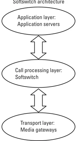
An understanding of thepublic switched telephone network(PSTN) and how it is potentially going to be replaced is best grasped by understanding its three major components: access, switching, and transport. Access pertains to how a user accesses the network. Switching refers to how a call is “switched” or routed through the network, and transport describes how a call travels or is “trans-ported” over the network.
Access
As mentioned,access refers to how the user “accesses” the telephone network. For most users, access is gained to the network via a telephone handset. Trans-mission is a diaphragm in the mouthpiece that converts the air pressure of voice into an analog electromagnetic wave for transmission to the switch. The earpiece performs this process in reverse.
The most sophisticated aspect of the handset is itsdual-tone multifrequency (DTMF) function, which signals the switch by tones. The handset is usually con-nected to the central office, where the switch is located, via copper wire known as twisted pair because, in most cases, it consists of a twisted pair of copper wire. The stretch of copper wire or, in newer installations, fiber-optic cable, connects the telephone handset to the central office. Everything that runs between the sub-scriber and the central office is known asoutside plant.Telephone equipment at the subscriber end is calledcustomer-premises equipment(CPE).
The emergence of wireless broadband Internet technologies such as 802.11a/b potentially allows the copper wires that have traditionally tethered residential and small business markets to telephone companies to be bypassed.
By not having to use copper wire to reach a residence or business, a competing service provider avoids the expense of the copper wire infrastructure as well as the legal entanglements of right of way and other issues to deploy a service that can compete with that of the incumbent service provider.
A market has sprung up in voice technologies for 802.11a/b networks. Major telecommunications equipment vendors such as Motorola, Cisco, and Avaya have products aimed at voice-over-wireless data networks. The focus of these industries is currently in the enterpriselocal-area network(LAN) market, however, it is not a stretch of the imagination to expect these technologies to, step by step, take market share from incumbent telephone service providers. The Telecommunications Act of 1996 was intended to open access to those copper wires for competing telephone companies (also known as competitive local exchange carriersor CLECs). It failed to do so to a meaningful degree. Competi-tion will most likely cometothe local loop, notinthe local loop.
Switching
The PSTN is a star network, in which every subscriber is connected to another via at least one if not many hubs known asoffices.In those offices are switches. Very simply, there are local offices for local service connections and tandem offices for long-distance service connections. Local offices, better known as cen-tral officesor COs, use Class 5 switches and tandem offices use Class 4 switches.
The late 1990s marked the emergence of the commercialVoice over Inter-net Protocol(VoIP). VoIP used a technology known assoftswitchto replace Class 4 and Class 5 switches. A softswitch is simply software hosted on a server con-nected to an IP network. Instead of costing tens of millions of dollars and occu-pying vast CO space in expensive metro locations, a softswitch can be hosted almost anywhere on a server the size of a small refrigerator. Softswitch platforms cost a fraction of a Class 5 switch. By not having to route voice traffic through the incumbent service providers’ Class 5 or Class 4 switches, a competing service provider could enjoy a greatly lowered barrier to entry to the voice market. The Telecommunications Act of 1996 was supposed to open the incumbent tele-phone companies’ switching infrastructures to competitors, but it failed to do so. A softswitch allows a new market entrant to bypass the incumbent’s Class 5 switch.
Transport
technology sparked a boom in the construction of IP backbones, which led to bandwidth glut,” that is, an overabundance of capacity on those networks. Con-trary to traditional telephone networks, all a VoIP service provider needed to offer long-distance service was a connection to an IP backbone.
Vo802.11: Bypassing the Local Loop
The emergence ofvoice over 802.11 (Vo802.11) was made possible by simply moving VoIP over 802.11 as an access mechanism, thereby replacing the copper wires of the PSTN. Once the VoIP stream reaches the wired part of such a net-work (the access point), it is transported on an IP netnet-work (LAN, IP backbone). By being based on the IP, VoIP can be managed (switched) by a VoIP-specific switch, the softswitch discussed in the preceding section. Although the conversa-tion may originate and be switched on an IP network, it is still possible to origi-nate and termiorigi-nate calls on the PSTN. This is made possible with the interface of a VoIP gateway between the IP network and the PSTN. This gateway, depending on the direction of the flow of the traffic, packetizes or depacketizes the voice traffic traveling between the two dissimilar networks.
In summary, it is now possible to completely bypass the PSTN. By sup-planting the elements of the PSTN with IP-based technologies, it is now possi-ble to completely replicate the PSTN function for function. Not only does this represent a replacement of the PSTN, it is also makes possible a myriad of new elements for such a function. Application servers that operate with softswitches allow for the rapid creation of new features that were either not possible with the circuit-switched PSTN or would have cost the service provider too much to jus-tify deployment.
This thesis is not without opposition. A number of objections to the deployment of Vo802.11 remain. Those objections are focused on concerns that the two chief elements of Vo802.11, that is, VoIP and 802.11, have perceived weaknesses that prevent them from delivering the same levels of service as the PSTN. After explaining the workings of the PSTN, 802.11, and VoIP, this book will overcome those objections.
Reference
2
802.11: Alternative Access
What, technically speaking, is 802.11b and how does it relate to IEEE 802.11? This chapter covers the technology of transmitting data over the airwaves, the process of that transmission, and the topologies and components of wireless net-works. Thousands of enterprises worldwide are “cutting the wires” to their LANs to enjoy greater productivity from their unwired workforce. The 802.11b technology also presents the potential to save money on infrastructure (wiring buildings for networks) and telecommunications services.
Because Vo802.11 is VoIP transmitted on 802.11, it is necessary to under-stand how this transmission medium functions. Just as voice has been transmit-ted overasynchronous transfer mode(ATM), frame relay, X.25, and the Internet Protocol, it can also be transmitted on 802.11. This chapter discusses how 802.11 works. From this, the reader will gain a better understanding of how 802.11 can be used to transmit voice.
How Does WiFi Work?
A networked desktop computer is connected to a larger network [LAN, wide-area network(WAN), Internet] via a network cable to a hub, router, or switch. The computer’s network interface card sends zeros and ones down the cable by changing the voltage on the wires from+5V to –5V in a prearranged cadence. WiFi simply replaces these cables with small, low-powered two-way radios. Instead of changing voltage on a wire, it encodes the zeros and ones by laying an alternating radio signal over a constant existing signal, again in a prearranged cadence. The alternating signal encodes zeros and ones on the radio waves. The 802.11b specification allows for the wireless transmission of approximately
11 Mbps of raw data at distances up to a few hundred feet over the 2.4-GHz unlicensed band. The distance depends on impediments, materials, and line of sight.
The big “so what!?” of this technology is that it means PC users can install $40 PC cards in their laptops or PDAs and be connected just as well to the Internet or their corporate networks as if they were still tied to their desks and wall outlets by a physical wire. Enterprises have been quick to adopt this tech-nology because (1) it is not constrained by the cost of wiring a building for voice and data, (2) it improves worker productivity by allowing mobility within a building or corporate campus, (3) it does not require right-of-way agreements to bring service to a business, (4) it is independent of distance to CO limitations, and (5) it is relatively free of federal, state, and local regulations.
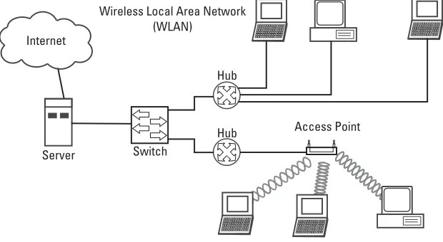
Awireless local-area network(WLAN) installation usually uses one or more access points(AP), which are dedicated stand-alone hardware with typically more powerful antennas. Figure 2.1 illustrates a wireless LAN. In addition to servicing enterprise networks, 802.11b has become the most popular standard for public short-range networks, known as hot spots, which are found at airports, hotels, conference centers, and coffee shops and restaurants. Several companies cur-rently offer paid hourly, session-based, or unlimited monthly access via their deployed networks around the United States and internationally [1].
How Data Is Transmitted Via Wireless Technology
The 802.11 standard provides for two radio-frequency (RF) variations (as opposed to infrared) of the physical layer:direct sequence spread spectrum(DSSS) andfrequency hopping spread spectrum (FHSS). Both of these were designed to
Wireless Local Area Network (WLAN)
Hub
Server Switch
Internet
Access Point Hub
comply with FCC regulations (FCC 15.247) for operation in the 2.4-GHz band, which is an unlicensed spectrum. 802.11b uses DSSS.
DSSS systems use technology similar to that ofGlobal Positioning System (GPS) satellites and some types of cell phones. Each information bit is com-bined with a longerpseudorandom numerical(PN) in the transmission process. The result is a high-speed digital stream, which is then modulated onto a carrier frequency usingdifferential phase-shift keying(DPSK). DSSS works by taking a data stream of zeros and ones and modulating it with a second pattern, the chip-ping sequence. The sequence is also known as theBarker code,which is an 11-bit sequence (10110111000). The chipping or spreading code is used to generate a redundant bit pattern to be transmitted, and the resulting signal appears as wideband noise to the unintended receiver. One of the advantages of using spreading codes is that even if one or more of the bits in the chip are lost during transmission, statistical techniques embedded in the radio can recover the origi-nal data without the need for retransmission. The ratio between the data and width of the spreading code is calledprocessing gain.It is 16 times the width of the spreading code and increases the number of possible patterns to 64,000 (216), thus reducing the chances of cracking the transmission.
The DSSS signaling technique divides the 2.4-GHz band into fourteen 22-MHz channels, of which 11 adjacent channels overlap partially and the remaining three do not overlap. Data are sent across one of these 22-MHz chan-nels without hopping to other chanchan-nels, causing noise on the given channel. To reduce the number of retransmissions and noise, chipping is used to convert each bit of user data into a series of redundant bit patterns called chips. The inherent redundancy of each chip, combined with spreading the signal across the 22-MHz channel, provides the error checking and correction functionality to recover the data. Spread spectrum products are often interoperable because many are based on the IEEE 802.11 standard for wireless networks. DSSS is used primarily in interbuilding LANs, because its properties are fast and far reaching [2].
At the receiver, a matched filter correlator is used to remove the PN sequence and recover the original data stream. At a data rate of 11 Mbps, DSSS receivers use different PN codes and a bank of correlators to recover the trans-mitted data stream. The high rate modulation method is calledcomplementary code keying(CCK).
The Significance of Spread Spectrum Radio
One of the basic technologies underlying the IEEE 802.11 series of standards is spread spectrum radio. The fundamental concept of spread spectrum radio is that it uses a wider frequency bandwidth than that needed by the information that is transmitted. Using extra bandwidth would seem to be wasteful, but it actually results in several benefits, including reduced vulnerability to jamming, less susceptibility to interference, and coexistence with narrowband transmis-sions. There are several spread spectrum techniques including time hopping, fre-quency modulation, FHSS, DSSS, and hybrids of these.
FHSS and DSSS are not modulation techniques, but simply methods of distributing a radio signal across bandwidth. In addition to spreading the signal across a frequency band, spread spectrum systems modulate the signal. Modula-tion is the variation of a radio signal to convey information. The base signal is called thecarrier.The variation may be based on the strength (amplitude modu-lation), frequency, or phase (frequency offset) of the signal. The modulation technique directly affects the data rate. Higher data rate modulations are gener-ally more complex and expensive to implement. Modulations resulting in higher data rates pack more information in the same bandwidth. Small disruptions in the signal cause the degradation of more data. This means that the signal must have a higher signal-to-noise ratio (SNR) at the receiver to be effectively proc-essed. Because a radio signal is stronger the closer it is to the source, the SNR decreases with distance. This is why higher speed systems have less range. Exam-ples of modulation techniques used in the IEEE 802.11 series of specifications are binary phase-shift keying (BPSK), quadrature phase-shift keying (QPSK), Gaussian frequency-shift keying(GFSK), and CCK.
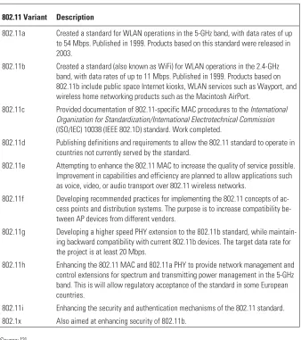
802.11 Variants
In 1997 theInstitute of Electrical and Electronics Engineers(IEEE) adopted IEEE Standard 802.11-1997, the first WLAN standard. This standard defines the media access control(MAC) and physical (PHY) layers for a LAN with wireless connectivity. It addresses local-area networking, in which the connected devices communicate over the air to other devices that are within proximity to each other. This is illustrated in Figure 2.2.
FHSS (802.11a)
Spread spectrum radio techniques originated in the U.S. military in the 1940s. The unlikely copatent holders on spread spectrum technology are the actress Hedy Lamar and musician George Antheil. Lamar had been married to a Ger-man arms dealer and fled GerGer-many as the Nazis came to power. One of Antheil’s techniques involved the use of player pianos. These two facts came together to create one of the twentieth century’s most influential radio technologies.
The military had started to use radio as a remote control mechanism for torpedoes, but this technique suffered from a vulnerability to jamming. Aware of this, Lamar suggested to Antheil that the radio signal should be distributed randomly over time across a series of frequencies. The transmission on each fre-quency would be brief and make the aggregate less susceptible to interruption or jamming. The problem was synchronizing the transmitter and receiver to the frequency being used at any point in time. Antheil used his musical expertise to design a synchronization mechanism using perforated paper rolls like those found in player in player pianos.
Lamar and Antheil were awarded U.S. patent number 2,292,387 and gave the rights to the Navy in support of the war effort. Although the Navy did not deploy the technology, engineers at Sylvania Electronic Systems applied elec-tronic synchronization techniques to the concept in the late 1950s. The U.S.
Application
military began using these systems for secure communications in the early 1960s. The spread spectrum technique spawned from the work of Hedy Lamar and George Antheil is what we now call FHSS.
Local authorities also regulate the hopping rate. In North America, the hopping rate is set at 2.5 hops per second with each transmission occupying a channel for less than 400 milliseconds. Channel occupancy is also calleddwell time. In 2001, the Federal Communications Commission (FCC) proposed to amend its Part 15 rules to allow adaptive hopping techniques to be used. This rulemaking is designed to reduce interference with other systems operating at
Table 2.1 IEEE 802.11 Variants
802.11 Variant Description
802.11a Created a standard for WLAN operations in the 5-GHz band, with data rates of up to 54 Mbps. Published in 1999. Products based on this standard were released in 2003.
802.11b Created a standard (also known as WiFi) for WLAN operations in the 2.4-GHz band, with data rates of up to 11 Mbps. Published in 1999. Products based on 802.11b include public space Internet kiosks, WLAN services such as Wayport, and wireless home networking products such as the Macintosh AirPort.
802.11c Provided documentation of 802.11-specific MAC procedures to theInternational Organization for Standardization/International Electrotechnical Commission (ISO/IEC) 10038 (IEEE 802.1D) standard. Work completed.
802.11d Publishing definitions and requirements to allow the 802.11 standard to operate in countries not currently served by the standard.
802.11e Attempting to enhance the 802.11 MAC to increase the quality of service possible. Improvement in capabilities and efficiency are planned to allow applications such as voice, video, or audio transport over 802.11 wireless networks.
802.11f Developing recommended practices for implementing the 802.11 concepts of ac-cess points and distribution systems. The purpose is to increase compatibility be-tween AP devices from different vendors.
802.11g Developing a higher speed PHY extension to the 802.11b standard, while maintain-ing backward compatibility with current 802.11b devices. The target data rate for the project is at least 20 Mbps.
802.11h Enhancing the 802.11 MAC and 802.11a PHY to provide network management and control extensions for spectrum and transmitting power management in the 5-GHz band. This is will allow regulatory acceptance of the standard in some European countries.
802.11i Enhancing the security and authentication mechanisms of the 802.11 standard.
802.1x Also aimed at enhancing security of 802.11b.
the 2.4-GHz frequencies. Studies have shown that up to 13 IEEE 802.11 FHSS systems can be colocated before frequency channel collisions become an issue [4, pp. 124–126].
DSSS
DSSS systems mix high-speed bit patterns with the information being sent to spread the RF carrier. Each bit of information has a redundant bit pattern asso-ciated with it, effectively spreading the signal over a wider bandwidth. These bit patterns vary in length and the rate at which they are mixed into the RF carrier. They are calledchipsorchipping codesand vary in length from as small as 11 bits to extremely long sequences. The speed at which they are transmitted is called thechipping rate.To an observer, these sequences appear to be noise and are also calledpseudorandom noise codes (Pncodes). Pncodes are usually introduced into the signal through the use of hardware-based shift registers, and the techniques used to introduce them are divided into several groups including Barker codes, Gold codes, M-sequences, and Kasami codes.
These spreading codes allow the use of statistical recovery methods to repair damaged transmissions. Another side effect of spreading the signal is lower spectral density—that is, the same amount of signal power is distributed over more bandwidth. The effect of a less spectrally dense signal is that it is less likely to interfere with spectrally dense narrowband signals. Narrowband signals are also less likely to interfere with a DSSS signal because the narrowband signal is spread as part of the correlation function at the receiver.
The frequency channel in IEEE 802.11 DSSS is 22-MHz wide. This means that it supports three nonoverlapping channels for operation. This is why only three IEEE 802.11b DSSS systems can be colocated.
In addition to spreading the signal, modulation techniques are used to encode the data signal through predictable variations of the radio signal. IEEE 802.11 specifies two types of DPSK modulation for DSSS systems. The first is BPSK and the second is QPSK.Phase-shift keying(PSK), as the name implies, detects the phase of the radio signal. BPSK detects 180-degree inversion of the signal, representing a binary 0 or 1. This method has an effective data rate of 1 Mbps. QPSK detects 90-degree phase shifts. This doubles the data rate to 2 Mbps. IEEE 802.11b adds CCK and packet binary convolutional coding (PBCC), which provide data rates up to 11 Mbps [4, pp. 126–128].
Orthogonal Frequency-Division Multiplexing
Laboratories patented OFDM in 1970 and it is based on a mathematical process called thefast Fourier transform(FFT). FFT enables 52 channels to overlap with-out losing their individuality or orthogonality. Overlapping channels is a more efficient use of the spectrum and enables them to be processed at the receiver more efficiently. IEEE 802.11a OFDM divides the carrier frequency into 52 low-speed subcarriers. Forty-eight of these carriers are used for data and four are used as pilot carriers. The pilot subcarriers allow frequency alignment at the receiver.
One of the biggest advantages of OFDM is its resistance to multipath interference and delay spread. Multipath is caused when radio waves reflect and pass through objects in the environment. Radio waves are attenuated or weak-ened in a wide range depending on the object’s materials. Some materials (such as metal) are opaque to radio transmissions. You can imagine that a cluttered environment would be very different from an open warehouse environment for radio wave transmission and reception. This environmental variability is why it is so hard to estimate the range and data rate of an IEEE 802.11 system. Because of reflections and attenuation, a single transmission can be at different signal strengths and from different directions depending on the types of materials it encounters. This is themultipathaspect of interference. IEEE 802.11a supports data rates from 6 to 54 Mbps. It utilizes BPSK, QPSK, and QAM to achieve the various data rates.
Delay spreadis associated with multipath. Because the signal is traveling over different paths to the receiver, the signal arrives at different times. This is delay spread. As the transmission rate increases, the likelihood of interference from previously transmitted signals increases. Multipath and delay spread are not much of an issue at data rates less than 3 or 4 Mbps, but some sort of mecha-nism is required as rates increase to mitigate the effect of multipath and delay spread. In IEEE 802.11b, it is CCK modulation. In 802.11a, it is OFDM. The IEEE 802.11g specification also uses OFDM as its frequency management mechanism [4, p. 131].
The adoption and refinement of advanced semiconductor materials and radio transmission technologies for IEEE 802.11 provides a solid basis for the implementation of higher-level functions. The next step up the protocol ladder is the definition of access functionality. Without structured access, the physical medium would be unusable [4, pp. 99, 129–131].
(CDMA) in its approach. CDMA uses complex mathematical transforms to put multiple transmissions onto a single carrier; OFDM encodes a single transmis-sion into multiple subcarriers. The mathematics underlying the code divitransmis-sion in CDMA is far more complicated than in OFDM. OFDM devices use one wide-frequency channel by breaking it up into several component subchannels. Each subchannel is used to transmit data. All the low subchannels are then multi-plexed into one “ast” combined channel.
Carrier Multiplexing
When network managers solicit user input on network build-outs, one of the most common demands is for more speed. The hunger for increased data trans-mission has driven a host of researchers to search for ways to increase the speed of their technologies. OFDM takes a qualitatively similar approach to multilink PPP: When one link is not enough, use several in parallel.
OFDM is closely related to plain old frequency division multiplexing (FDM). Both “divide” the available bandwidth into slices calledcarriersor sub-carriersand make those carriers available as distinct channels for data transmis-sion. OFDM boosts throughput by using several subcarriers in parallel and multiplexing data over the set of subcarriers.
Traditional FDM was widely used by first-generation mobile telephones as a method for radio channel allocation. Each user was given an exclusive chan-nel, and guard bands were used to ensure that spectral leakage from one user did not cause problems for users of adjacent channels [5, p. 199].
MAC Concepts and Architecture
The IEEE 802.11 MAC layer is common to all IEEE 802.11 PHY layers and specifies the functions and protocols required for control and access. The MAC layer is responsible for managing data transfer from higher level functions to the physical media. Figure 2.2, earlier in this chapter, illustrates this relationship to the OSI model.
MAC Layer Services
utilizes a set of messages with information elements that are pertinent to the services. These services are described in Table 2.2.
Power Management and Time Synchronization
In addition tocarrier-sense multiple-access /collision avoidance(CSMA/CA) con-trol frames (RTS, CTS, ACK, and contention polling), the MAC also provides control frames for power management and time synchronization. APs provide a time synchronization beacon to associated stations in an infrastructure basic service set (BSS). In an independent BSS, in which stations are operating as peers, an algorithm is defined that enables each station to reset its time when it receives a synchronization value greater than its current value. Stations entering a power-save mode may inform a PC through the frame control field of a mes-sage. The AP will then buffer transmissions to the station. A station is informed that it has buffered transmissions waiting when it wakes periodically to receive beacon frames. It can then request transmission. A station in active mode can receive frames at any time during a contention-free period. A station in power-save mode will periodically enter the active mode to receive beacons, broadcast, multicast, and buffered data frames [5, p. 128].
MAC Layer Architecture
Table 2.2
IEEE 802.11 MAC Services and Agents
MAC Service Definition
Station Type Authentication Because wireless LANs have limited physical security to prevent
unau-thorized access, 802.11 defines authentication services to control ac-cess to the WLAN. The goal of the authentication service is to provide access control equal to that of a wired LAN. The authentication service provides a mechanism for one station to identify another station. With-out this proof of identity, the station is not allowed to use the WLAN for data delivery. All 802.11 stations, whether they are part of an inde-pendent BSS orextended service set (ESS) network, must use the authentication service prior to communicating with another station.
End-point and AP
Open system authentication
This is the default authentication method, which is a very simple, two-step process. First, the station wanting to authenticate with another station sends an authentication management frame containing the sending station’s identity. The receiving station then sends back a frame alerting whether it recognizes the identity of the authenticating station.
Shared key authentication
This type of authentication assumes that each station has received a secret shared key through a secure channel independent of the 802.11 network. Stations authenticate through shared knowledge of the secret key. Use of shared key authentication requires implementation of en-cryption via theWired Equivalent Privacy (WEP) algorithm
Deauthentication Removes an existing authentication. The deauthentication service is used to eliminate a previously authorized user from any further use of the network. Once a station is deauthenticated, that station is no longer able to access the WLAN without performing the authentication func-tion again.
Deauthentication is a notification and cannot be refused. For example, when a station wishes to be removed from a BSS, it can send a deauthentication management frame to the associated access point to notify the AP of the removal from the network. An AP could also deauthenticate a station by sending a deauthentication frame to the station.
End-point and AP
Association Maps a station to an access point and enables the AP to distribute data to and from the station The association service is used to make a logi-cal connection between a mobile station and an AP. Each station must become associated with an AP before it is allowed to send data through the AP onto the distribution system. The connection is neces-sary in order for the distribution system to know where and how to de-liver data to the mobile station. The mobile station invokes the association service once and only once, typically when the station en-ters the BSS. Each station can associate with only one AP, although an AP can associate with multiple stations.
Table 2.2(continued)
Mac Service Description
Station Type Disassociation Breaks an existing association relationship. The disassociation service
is used either to force a mobile station to eliminate an association with an access point or for a mobile station to inform an AP that it no longer requires the services of the DS. When a station becomes disassociated, it must begin a new association to communicate with an AP again. An AP may force a station or stations to disassociate because of re-source restraints or if the access point is being shut down or removed from the network for a variety of reasons. When a mobile station is aware that it will no longer require the services of an AP, it may invoke the disassociation service to notify the access point that the logical connection to the services of the access point from this mobile station is no longer required.
Stations should disassociate when they leave a network, although there is nothing in the architecture to ensure that this happens. Disas-sociation is a notification and can be invoked by either associated party. Neither party can refuse termination of the association.
AP
Reassociation Transfers an association between APs. Reassociation enables a station to change its current association with an access point. The reassocia-tion service is similar to the associareassocia-tion service, with the excepreassocia-tion that it includes information about the access point with which a mobile sta-tion has been previously associated. A mobile stasta-tion will use the reas-sociation service repeatedly as it moves throughout the ESS, loses contact with the AP with which it is associated, and needs to become associated with a new access point.
By using the reassociation service, a mobile station provides informa-tion to the AP with which it will be associated and informainforma-tion pertain-ing to the AP with which it will be disassociated. This allows the newly associated AP to contact the previously associated AP to obtain frames that may be waiting there for delivery to the mobile station as well as other information that may be relevant to the new association. The mo-bile station always initiates reassociation.
AP
Privacy Prevents unauthorized viewing of data through use of the WEP algorithm. The privacy service of IEEE 802.11 is designed to provide an equivalent level of protection for data on the WLAN as that provided by a wired net-work with restricted physical access. This service protects that data only as they traverse the wireless medium. It is not designed to provide com-plete protection of data between applications running over a mixed net-work.
With a wireless network, all stations and other devices can “hear” data traffic taking place within range on the network, seriously impacting the security level of a wireless link. IEEE 802.11 counters this problem by offering a privacy service option that raises the security of the
MAC data transfer is controlled through two distinct coordination func-tions. The first is thedistributed coordination function(DCF), which defines how users contend for the medium as peers. DCF data transfers are not time sensitive and delivery is asynchronous. The second is the point coordination function (PCF), which provides centralized traffic management for data transfers that are sensitive to delay and require contention-free access [4, pp. 134–135].
MIB
IEEE 802.11 contains extensive management functions to make the wireless connection appear much like a regular wired connection. The complexity of the
Table 2.2(continued)
MAC Service Description
Station Type 802.11 network to that of a wired network. The privacy service, apply-ing to all data frames and some authentication management frames, is an encryption algorithm based on the 802.11.
Distribution Provides data transfer between stations through the DS. Distribution is the primary service used by an 802.11 station. A station uses the distri-bution service every time it sends MAC frames across the DS. The dis-tribution service provides the disdis-tribution with only enough information to determine the proper destination BSS for the MAC frame.
The three association services (association, reassociation, and disasso-ciation) provide the necessary information for the distribution service to operate. Distribution within the DS does not necessarily involve any ad-ditional features outside of the association services, although a station must be associated with an access point for the distribution service to forward frames properly.
AP
Data delivery Provides transfer of data between stations. End-point and AP
Integration Provides data transfer between the DS of an IEEE 802.11 LAN and a non-IEEE 802.11 LAN. The station providing this function is called a por-tal. The integration service connects the 802.11 WLAN to other LANs, including one or more wired LANs or 802.11 walls. A portal performs the integration service. The portal is an abstract architectural concept that typically resides in an AP, although it could be part of a separate network component entirely.
The integration service translates 802.11 frames to frames that may traverse another network.
AP
additional management functions results in a complex management entity with dozens of variables. For ease of use, the variables have been organized into a management information base so that network managers can benefit from tak-ing a structured view of the 802.11 parameters. The formal specification of the 802.11 MIB is Annex D of the 802.11 specification. The 802.11 MIB was designed by the 802.11 working group [5, p. 383].
DCF
The distributed coordination function defines how the medium is shared among members of the wireless network. It provides mechanisms for negotiat-ing access to the wireless medium as well as mechanisms for reliable data deliv-ery. One of the fundamental differences between wired and wireless media is that it is difficult to detect and manage data collisions on wireless media. The primary reason for this is that stations in a radio network are not guaranteed to hear every other station’s transmissions. This is typically the case when an AP is used in IEEE 802.11’s infrastructure BSS and is called thehidden-node problem.
PCF
The point coordination function (PCF) polls associated stations and manages frame transmissions on their behalf. A station performing PCF traffic manage-ment is called apoint coordinator(PC). The PCF is an optional capability that provides connection-oriented services for delay-sensitive traffic. The PCF is more complex to implement, but it provides a moderate level of priority frame delivery for time-sensitive transmissions.
The PC uses beacon signals to broadcast duration for a contention-free period to all associated stations. This causes them to update theirnetwork alloca-tion vector (NAV) and wait for the duration of the contention-free period. In addition, stations must await thePCF interframe space(PIFS) interval to further decrease the possibility of data collisions. The transmission of the additional polling and ACK messages required by the PCF is optimized through piggy-backing multiple messages in a single transmission. For example, the PC may append both acknowledgments(Ax) of previous transmissions and polling mes-sages for new traffic to a data frame. This enables the transmission to avoid wait-ing the interframe interval specified for individual frame transmissions [4, pp. 140–141].
multiple stations from seizing the medium immediately after completion of the preceding transmission.
Packet reception in DCF requires acknowledgment as shown in Figure 2.3. The period between completion of packet transmission and start of the ACK frame is oneshort interframe space(SIFS). ACK frames have a higher prior-ity than other traffic. Fast acknowledgment is one of the salient features of the 802.11 standard, because it requires ACKs to be handled at the MAC sublayer.
Transmissions other than ACKs must wait at least one DCF interframe space(DIFS) before transmitting data. If a transmitter senses a busy medium, it determines a random back-off period by setting an internal timer to an integer number of slot times. On expiration of a DIFS, the timer begins to decrement. If the time reaches zero, the station may begin transmission. If the channel is seized by another station before the timer reaches zero, the timer setting is retained at the decremented value for subsequent transmission. The method described above relies on the physical carrier sense. The underlying assumption is that every station can “hear” all other stations [7].
IEEE 802.11 Architecture
IEEE 802.11 supports three basic topologies for WLANs: theindependent basic service set(IBSS), the BSS, and the ESS. All three configurations are supported by the MAC layer implementation.
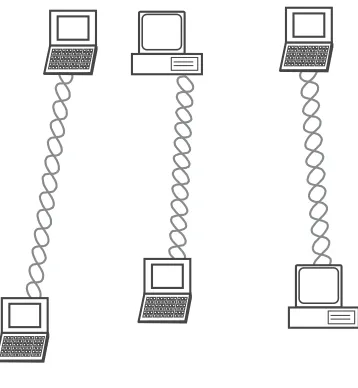
The 802.11 standard defines two modes: ad hoc/IBSS and infrastructure mode. Logically, an ad hoc configuration (Figure 2.4) is analogous to a peer-to-peer office network in which no single node is required to function as a server. IBSS WLANs include a number of nodes or wireless stations that communicate directly with one another on an ad hoc, peer-to-peer basis, building a full-mesh or partial-mesh topology. Generally, ad hoc implementations cover a limited area and are not connected to a larger network.
Src
Dest
Other
Defer access Backoff after defer
Contention window DIFS
SIFS Data
ACK
DIFS
Usinginfrastructuremode, the wireless network consists of at least one AP connected to the wired network infrastructure and a set of wireless end stations. This configuration is called abasic service set(Figure 2.5). Because most corpo-rate WLANs require access to the wired LAN for services (file servers, printers, Internet links), they will operate in infrastructure mode and rely on an AP that acts as the logical server for a single WLAN cell or channel. Communications between two nodes, A and B, actually flow from node A to the AP and then from the AP to node B. The AP is necessary to perform a bridging function and
Ad hoc network
Figure 2.4 Wireless ad hoc network.
Basic service set (BSS)
Server Switch
Internet
Access Point Hub
connect multiple WLAN cells or channels, and to connect WLAN cells to a wired enterprise LAN.
Anextended service setis a set of two or more BSSs forming a single subnet-work (Figure 2.6). ESS configurations consist of multiple BSS cells that can be linked by either wired or wireless backbones. IEEE 802.11 supports ESS con-figurations in which multiple cells use the same channel, and use different chan-nels to boost aggregate throughput.
IEEE 802.11 Components
IEEE 802.11 defines two pieces of equipment, a wirelessstation, which is usu-ally a PC equipped with a wireless network interface card (NIC) and an access point, which acts as a bridge between the wireless and wired networks. An AP usually consists of a radio, a wired network interface (802.3, for example), and bridging software conforming to the 802.11d bridging standard. The AP acts as the base station for the wireless network, aggregating access for multiple wireless stations onto the wired network. Wireless end stations can be 802.11 PC card, PCI, or ISA NICs, or embedded solutions in non-PC clients (such as an 802.11-based telephone handset).
An 802.11 WLAN is based on a cellular architecture. Each cell (BSS) is connected to the base station or AP. All APs are connected to a DS, which is similar to a backbone, usually Ethernet or wireless. All mentioned compo-nents appear as an 802 system for the upper layers of OSI and are known as the ESS.
Extended service set (ESS)
Hub
Server Switch
Internet
Access Point Hub
The 802.11 standard does not constrain the composition of the DS; there-fore, it may be 802 compliant or nonstandard. If data frames need transmission to and from a non-IEEE 802.11 LAN, then these frames, as defined by the 802.11 standard, enter and exit through a logical point called aportal. The portal provides logical integration between existing wired LANs and 802.11 LANs.
When the distribution system is constructed with 802-type components, such as 802.3 (Ethernet) or 802.5 (token ring), then the portal and the access point are the same, acting as a translation bridge.The 802.11 standard defines the distribution system as an element that interconnects BSSs within the ESS via access points. The distribution system supports the 802.11 mobility types by providing logical services necessary to handle address-to-destination mapping and seamless integration of multiple BSSs. An access point is an addressable sta-tion, providing an interface to the distribution system for stations located within various BSSs. The independent BSS and ESS networks are transparent to the LLC layer [2].
Mobility
Mobility of wireless stations may be the most important feature of a wireless LAN. The chief motivation of deploying a WLAN is to enable stations to move about freely from location to location either within a specific WLAN or between different WLAN “segments.”
For compatibility purposes, the 802.11 MAC must appear to the upper layers of the network as a “standard” 802 LAN. The 802.11 MAC layer is forced to handle station mobility in a fashion that is transparent to the upper layers of the 802 LAN stack. This forces functionality into the 802.11 MAC layer that is typically handled by upper layers in the OSI model [6].
To understand this design restriction, it is important first to appreciate the difference between true mobility and mere portability. Portability certainly results in a net productivity gain because users can access information resources wherever it is convenient to do so. At the core, however, portability removes only the physical barriers to connectivity. It is easy to carry a laptop between sev-eral locations, so people do. But portability does not change the ritual of con-necting to networks at each new location. It is still necessary to physically connect to the network and reestablish network connections, and network con-nections cannot be used while the device is being moved.
Mobility removes further barriers, most of which are based on the logical network architecture. Network connections stay active even while the device is in motion. This is critical for tasks requiring persistent, long-lived connections, which may be found in database applications.
network freely, but IP, as it is currently deployed, provides no way to move across subnet boundaries. To the IP-based hosts of the outside world, thevirtual private network(VPN) access control boxes are the last hop routers. To access an 802.11 wireless station with an IP address on the wireless network, it is possible to simply go through the IP router to the target network regardless of whether a wireless station is connected to the first or third AP. The target network is reach-able through the last hop router. As far as the outside world can tell, the wireless station might as well be a workstation connected to an Ethernet.
A second requirement for mobility is that the IP address does not change when connecting to any of the access points. New IP addresses interrupt open connections. If a wireless station connects to the first AP, it must keep the same address when it connects to the third AP.
A corollary to the second requirement is that all of the wireless stations must be on the same IP subnet. As long as a station stays on the same IP subnet, it does not need to reinitialize its networking stack and can keep its TCP con-nections open. If it leaves the subnet, though, it needs to get a new IP address and reestablish any open connections. Multiple subnets are not forbidden, but if you have different IP subnets, seamless mobility between subnets is not possible. The “single IP subnet backbone” restriction is a reflection on the technol-ogy deployed within most organizations. Mobile IP was standardized in late 1996 in RFC 2002, but it has yet to see widespread deployment. Until Mobile IP can be deployed, network designers must live within the limitations of IP and design networks based on fixed locations for IP addresses. A backbone network may be physically large, but it is fundamentally constrained by the requirement that all access points connect directly to the backbone router (and each other) at the link layer [5, pp. 295–296].
Conclusion
Some may argue that Morse code and the telegraph was the first technology that transmitted data via the airwaves (dots and dashes versus ones and zeros). The ability to transmit data over the airwaves presents some exciting opportunities for business networks. Businesses worldwide have made the switch from wired to wireless in order to save money and increase employee productivity.
connected to an existing LAN from which wireless stations can access the net-work. An ESS extends this topology to expand the netnet-work. Using an ad hoc topology, stations (PCs) can communicate directly with one another. Mobility measures permit wireless users to access the wireless network from any point on the network and maintain their connection regardless of where they may roam on the network.
What is exciting about 802.11 is that it allows the transmission of voice over a unlicensed spectrum. That is, for the cost of a radio and antenna, a service provider can offer voice services similar to that of a telephone or cell phone com-pany and avoid the expense of copper wires, right-of-way issues, and wireless cell phone spectrum. In short, 802.11 is an enabling technology that allows the local telephone companies to be bypassed.
References
[1] WiFi Consulting, “OK, What Is WiFi?” white paper, http://www.wificonsulting. com/WiFi101/wifi101.htm.
[2] Nedeltchev, P., “WLANS and the 802.11 Standard,” Cisco Systems white paper, March 2001, p. 7, http://wwwin.cisco.com/cct/data/itm/wan/sdlc/wtsdllca.htm.
[3] WAVE Report, “IEEE 802.11 Standard Tutorial,” http://www.wave-report.com/tutorials/ ieee80211.htm, November 29, 2001.
[4] LaRocca, J., and R. LaRocca,802.11 Demystified, New York: McGraw-Hill, 2002. [5] Gast, M.,802.11 Wireless Networks: The Definitive Guide,Sebastopol, CA: O’Reilly &
Associates, 2002.
[6] Intelligraphics, “Introduction to IEEE 802.11,” white paper, http://www.intelligraphics. com/articles/80211_article.html.
3
Voice over Internet Protocol
What Is VoIP?
Voice over 802.11 is voice over IP used to transport voice over wireless Ethernet. Many books about VoIP are available, so this book does not attempt to cover it in detail. Instead, this chapter briefly outlines how VoIP functions. The intent of this chapter is to give the reader a basic understanding of VoIP before discuss-ing Vo802.11.
Origins
In November 1988, Republic Telcom (yes, one “e”) of Boulder, Colorado, received U.S. patent number 4,782,485 for a “multiplexed digital packet tele-phone system.” The plaque from the Patent and Trademark Office describes it as follows:
A method for communicating speech signals from a first location to a sec-ond location over a digital communication medium comprising the steps of: providing a speech signal of predetermined bandwidth in analog signal format at said first location; periodically sampling said speech signal at a predetermined sampling rate to provide a succession of analog signal sam-ples; representing said analog signal samples in a digital format thereby pro-viding a succession of binary digital samples; dipro-viding said succession of binary digital samples into groups of binary digital samples arranged in a temporal sequence; transforming at least two of said groups of binary digital samples into corresponding frames of digital compression.
Republic and its acquiring company, Netrix Corporation, applied this voice-over-data technology to the data technologies of the times (X.25 and frame relay) until 1998 when Netrix and other competitors introduced VoIP onto their existing voice-over-data gateways. Although attempts at Internet telephony had been made from a software-only perspective, commercial applications were limited to using voice-over-data gateways that could interface the PSTN to data networks. Voice-over-data applications were popular in enterprise networks with offices spread across the globe (eliminated international interoffice long-distance bills), offices where no PSTN existed (installations for mining and oil companies), and for long-distance bypass (legitimate and illegitimate).
The popularity and applications of VoIP continued to grow. VoIP accounted for 6% of all international long-distance traffic in 2001 [1]. Six per-cent may not seem like an exciting number, but consider that a mere 3 years passed from when the technology was introduced to its capturing 6% of a trillion-dollar, 100-year-old industry—and it is clear that VoIP will continue to capture more market share. As VoIP migrates to 802.11 networks, it completes the bypass of the copper wires that tether residences and small business to incumbent telcos.
How Does VoIP Work?
Softswitch is increasingly considered to be almost synonymous with VoIP. However, it also works with TDM and ATM networks. The first process in an IP voice system is the digitization of the speaker’s voice. The next step (and the first step when the user is on a handset connected to a gateway using a digital PSTN connection) is typically the suppression of unwanted signals and com-pression of the voice signal. This has two stages. First, the system examines the recently digitized information to determine if it contains a voice signal or only ambient noise and discards any packets that do not contain speech. Second, complex algorithms are employed to reduce the amount of information that must be sent to the other party. Sophisticated codecs enable noise suppression and compression of voice streams. Compression algorithms include G.723, G.728, and G.729.
smaller networks. The network addressing system can often be very complex, requiring a process of encapsulating one packet inside another and, and as data move along, repackaging, readdressing, and reassembling the data.
When each packet arrives at the destination computer, its sequencing is checked to place the packets in the proper order. A decompression algorithm is used to restore the data to their original form, and clock synchronization and delay-handling techniques are used to ensure proper spacing. Because data pack-ets are transported via the network by a variety of routes, they do not arrive at their destination in order. To correct this, incoming packets are stored for a time in a jitter buffer to wait for late-arriving packets. The length of time in which data are held in the jitter buffer varies depending on the characteristics of the network.
In IP networks, a percentage of the packets can be lost or delayed, espe-cially during periods of congestion. Also, some packets are discarded due to errors that occurred during transmission. Lost, delayed, and damaged packets result in substantial deterioration of voice quality. In conventional error correc-tion techniques used in other protocols, incoming blocks of data containing errors are discarded, and the receiving computer requests the retransmission of the packet, thus the message that is finally delivered to the user is exactly the same as the message that originated. Because VoIP systems are time sensitive and cannot wait for retransmission, more sophisticated error detection and cor-rection systems are used to create sound to fill in the gaps. This process stores a portion of the incoming speaker’s voice and then, using a complex algorithm to approximate the contents of the missing packets, new sound information is cre-ated to enhance the communication. Thus, the sound heard by the receiver is not exactly the sound transmitted, but rather portions of it that have been cre-ated by the system to enhance the delivered sound [2].
Protocols Related to VoIP
The softswitch revolution was made possible by the emergence of voice over data and, more specifically, VoIP. Note that there are softswitch solutions that usetime-division multiplexing(TDM) and ATM. However, the consensus in the industry is that the future is going to be an IP network, ultimately dictating a VoIP solution. Before outlining softswitch solutions, it is first necessary to understand VoIP. VoIP is best understood as a collection of the protocols that make up its mechanics. Those protocols are loosely analogous to the PSTN, which is broken down into three categories: access, switching, and transport. Simply put, three categories of protocols are relevant to VoIP: signaling, rout-ing, and transport.
media stream or conversation. Gateway control protocols such as MGCP and MEGACO (also signaling protocols) establish control and status in media and signaling gateways.
Routing [using theUser Datagram Protocol(UDP) andTransmission Con-trol Protocol(TCP)] and transporting the media stream (conversation) once the route of the media stream has been established are the function of routing and transport protocols. Routing protocols such as UDP and TCP could be com-pared to the switching function described in Chapter 2.
RTP is analogous to the transport function. The signaling and routing functions establish what route the media stream will take and the routing proto-cols deliver the bits, that is, the conversation.
Signaling Protocols
The process of setting up a VoIP call is roughly similar to that of a circuit-switched call made on the PSTN. A media gateway must be loaded with the parameters to allow proper media encoding and the use of telephony features. Inside the media gateway is an intelligent entity known as anendpoint.When the calling and called parties agree on how to communicate and the signaling criteria have been established, the media stream over which the packetized voice conversation will flow is established. Signaling establishes the virtual circuit over the network for that media stream. Signaling is independent of the media flow. It determines the type of media to be used in a call. Signaling is concurrent throughout the call. Currently, two types of signaling are popular in VoIP: H.323 and SIP [3].
H.323
H.323 is theInternational Telecommunication Union(ITU-T) recommendation for packet-based multimedia communication. H.323 was developed before the emergence of VoIP. Because it was not specifically designed for VoIP, it has faced a good deal of competition from a competing protocol, theSession Initia-tion Protocol (SIP), which was designed specifically for VoIP. However, it has enjoyed a first-mover advantage and there now exists a considerable number of installed H.323 VoIP networks.
channel setup, and codec specifications for transmitting real-time video and voice over networks that do not offer guaranteed service or quality of service. As a transport, H.323 uses the Real-Time Transport Protocol (RTP), an Internet Engineering Task Force(IETF) standard designed to handle the requirements of streaming real-time audio and video via the Internet [3, p. 9]. H.323 was the first VoIP protocol for interoperability among the early VoIP gateway/gate-keeper vendors. Unfortunately, the promise of interoperability among diverse vendors platforms did not materialize with the adoption of H.323.
The H.323 standard is a cornerstone technology for the transmission of real-time audio, video, and data communications over packet-based networks. It specifies the components, protocols, and procedures that provide multimedia communication over packet-based networks. Packet-based networks include IP-based (including the Internet) orInternet packet exchange(IPX)-based LANs, enterprise networks (ENs), metropolitan-area networks (MANs), and WANs. H.323 can be applied in a variety of mechanisms—audio only (IP telephony); audio and video (videotelephony); audio and data; and audio, video, and data. H.323 can also be applied to multipoint-multimedia communications. H.323 provides myriad services and, therefore, can be applied in a wide variety of areas—consumer, business, and entertainment applications.
SIP
SIP is a signaling protocol. It uses a text-based syntax similar to that of the Hypertext Transfer Protocol(HTTP), which is used in Web addresses. Programs that are designed for parsing of HTTP can be adapted easily for use with SIP. SIP addresses, known as SIP uniform resource locators(URLs) take the form of Web addresses. A Web address can be the equivalent of a telephone number in a SIP network. In addition, PSTN phone numbers can be incorporated into a SIP address for interfacing with the PSTN. An e-mail address is portable. Using the proxy concept, one can check his or her e-mail from any Internet-connected ter-minal in the world. Telephone numbers, simply put, are not portable. They ring at only one physical location. SIP offers a mobility function that can follow a subscriber to whichever phone he or she is nearest at any given time.
and softswitch industry believe that SIP will replace H.323 as the standard sig-naling protocol for VoIP.
SIP is part of the IETF standards process and is modeled on other Internet protocols such asSimple Mail Transfer Protocol(SMTP) and HTTP. It is used to establish, change, and tear down (end) calls between one or more users in an IP-based network. To provide telephony services, a number of different stan-dards and protocols need to come together and work with each other specifically to ensure transport (RTP), provide signaling with the PSTN, guarantee voice quality (RSVP), provide directories (LDAP), authenticate users (RADIUS), and scale to meet anticipated growth curves.
What Is SIP?
SIP is focused on two classes of network entities:clients(also calleduser agents) and servers. VoIP calls on SIP originate at a client and terminate at a server. Types of clients in the technology currently available for SIP telephony would include a PC loaded with a telephony agent or a SIP telephone. Clients can also reside on the same platform as a server. For example, a PC on a corporate WAN might be the server for the SIP telephony application, but may also be used as a user’s telephone (client) [4, p. 89].
SIP Architecture
SIP is a client/server architecture. The client in this architecture is theuser agent (UA). The UA interacts with the user. It usually has an interface toward the user
SIP signaling stream
SIP signaling stream
RTP media stream
SIP phone SIP phone
SIP proxy server

![Figure 3.3 SIP call using a proxy server. (From: [5]. © 2001 Artech House, Inc. Reprintedwith permission.)](https://thumb-ap.123doks.com/thumbv2/123dok/1305374.2009792/50.432.116.313.52.265/figure-using-proxy-server-artech-house-reprintedwith-permission.webp)
![Figure 4.1 SS7 signaling points. (From: [4]. © 2003 Performance Technologies, Inc.Reprinted with permission.)](https://thumb-ap.123doks.com/thumbv2/123dok/1305374.2009792/72.432.121.309.488.571/figure-ss-signaling-points-performance-technologies-reprinted-permission.webp)
![Figure 4.2 Comparison of OSI reference model and SS7 protocol stacks. (From: [4]. © 2003Performance Technologies, Inc](https://thumb-ap.123doks.com/thumbv2/123dok/1305374.2009792/74.432.115.311.53.278/figure-comparison-reference-model-protocol-stacks-performance-technologies.webp)