Available online at http://www.iaeme.com/ijciet/issues.asp?JType=IJCIET&VType=9&IType=5 ISSN Print: 0976-6308 and ISSN Online: 0976-6316
© IAEME Publication Scopus Indexed
COMBINED STRUCTURE SPIDER NEST AND
REINFORCED CONCRETE PILE AS AN
ALTERNATIVE STORY BUILDING
FOUNDATION
Astawa D. Made, Sumaidi
Lecturer in Civil Engineering of Pembangunan Nasional University "Veteran" East Java
Faizal Anggriawan
Student in Civil Engineering of Pembangunan Nasional University “Veteran” East Java
ABSTRACT
The combined of Spider Nest Foundation (KSLL) with Reinforced Concrete Pile, is a combination of shallow foundation with deep foundation, is one of the alternative modification of foundation for middle level building with maximum floor number 8 levels. This design modeling foundation rib KSLL as the bearing wall with a cantilever-flops on the floor plate. Referring to the principle of mechanics with the clasp on the Plate, the worst condition when the other side of the rib has not been filled so that the rib will accept one side of the soil pressure, will result in the cantilever flexure moment as the base for reinforcement. With the addition a number of pile diameter of 50 cm at the corners of the building to minimize the decline. Based on analysis of the carrying KSLL capacity with safety factor SF=4 obtained qalow is 1426 kN/m2, and qult = 5703,2 kN/m2, after being given a pile strengthening, the carrying capacity increased to 14092 kN / m2. The result of determining KSLL declining analysis is a long-term consolidation decrease of 14.4 cm qualify < 15 cm. In the combined system of KSLL Foundation with reinforced concrete piling pole as deep as 11.00 m, the value of decrease is only 7.92 cm, so that the structure of the foundation of KSLL combined with Piling is very stable and qualified as the foundation of 8-storey building.
Keywords: Combination KSLL, Piling, Foundation, Bearing Capacity, Settlement. Cite this Article: Astawa D. Made, Faizal Anggriawan and Sumaidi, Combined Structure Spider Nest and Reinforced Concrete Pile as an Alternative Story Building Foundation, International Journal of Civil Engineering and Technology, 9(5), 2018, pp. 857–867.
1. INTRODUCTION
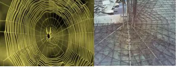
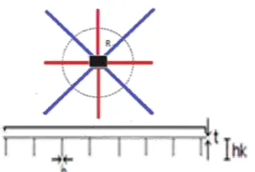
Soil improvement is required if the original soil bearing capacity is poor so that the top soil layer needs to be replaced with soil that has a better carrying capacity (Hidayatun et all, 2018). One solution is the foundation of spider nest Construction (KSLL) is a structure that utilizes soil media as part of the foundation structure which is able to anticipate the seismic forces both horizontally and vertically (Raharja and Sutjipto, 1984; Raharja, 2015). Called the Spiders Nest because the reinforcement of the foundation plate around a column is shaped interlocking webs monolithically resembles a spider Nest (Figure 1).The foundation plate is given a monolithic diagonal ribs support renderer so that the structure becomes a rigid that serves as a burden of gravity and earthquake loads. The foundation structure is relatively lighter because some of the volume of concrete is replaced by compacted soil.
Figure 1 The Idea of KSLL Structural Foundation (Education Media, 2018)
The KSLL foundation will uniformly decrease because the construction consists of a thin plate with a reinforced concrete ribs actuator that serves as a stress spreader due to the column load of the upper structure. Because KSLL is a shallow foundation category that carries the burden of Building structures up to 8 levels, a high enough settlement can not be avoided, although it does not lead to significant disruption to the stability of the building structure. So in this paper arises the idea to combine KSLL structure with reinforced concrete piles. We all know that the pile foundation when it comes to the depth of the stable point of the soil, the decline is very small. To be more economical (Samudro and Mangkoedihardjo, 2006; Sedayu and Mangkoedihardjo, 2018), the pile configuration will be installed at the exterior column points around the edge of the KSLL.
2. METODOLOGY
Building Modeling Design and dimensions are as follows:
Building Data
1. Number of Floors : 8 lantai + 1 basement 6) Wide of Foundation KSLL : 34,55 m 2. Deep of Basement : 2,3 m 7) Tall of Building: 30,04 m
3. Length 0f Building : 40 m 8) Typical Floor height: 3,20 m
The Modeling Structure result
Figure 2 Structural Modeling of Building 8 floors
Foundation Design
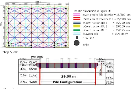
The result of combination design of KSLL Foundation with Pile is like Figure 3 below:
Top View
Cross Section
Figure 3 Foundation Design
4. RESULTS AND DISCUSSION
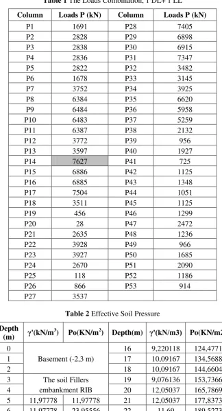
Large loads that work on Structure
Total load with a combination of loading:1 DL+1 LL, The combination of the largest loading components is used as the ultimate load to be used in foundation design
12 9,220118 87,76702 28 8,798925 250,8294 13 8,242051 96,00907 29 8,798925 259,6284 14 9,623952 105,633 30 8,798925 268,4273 15 9,623952 115,257
Effective Soil Pressure
Effective Soil pressure, tabulated as follows
The calculation of effective soil stress (Po) at a depth of 30 m is 268.43 kN / m2 (268,43 kPa), like tehe Table 2.
The Maximum Soil Stress
The length of the foundation plate KSLL (L) = 44m, Wide (B)=29,55m, Thick plate(D) = 0,15 m, Depth rib foundation = 3.0 m from the bottom of the basement floor.
Calculate the Stress then the qo max is 127,76 kPa
KSLL Bearing Capacity Analysis
Based on soil data, KSLL foundation rests on a 5,0 m thick sand soil, with cohesion C = 0 and sand shear force ϕ=28,578o, then Nq=15,689, Nc=26,97, and Nγ=12,33. Shape factors, depth,
and slope according to Mayerhof are: Kp=2,8341, sc=1,445, sq= 1,22, sγ=1,22 and dc=1,03, dq=1,01, dγ=1,01and are q=33,562 kN/m2,
so qult=5703,2 , and qaKSLL=
, Safety Factor: SF=16,24
Stress Controls Occurred
Building load divided by the area of the foundation, to calculate the magnitude of the voltage. Calculate the stress at the bottom of the foundation based on uniform load:
= =
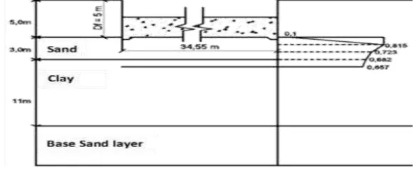
Settlement Analysis of KSLL
Result of instantaneous Sttlement (Si) on sand soil is: 253. 10-4 m = 25,3 mm (see Figure 4).
Settlement on soil Clay
The result: Si1 = 34 mm and Si2 = 15 mm
The results of calculation of total Settlement immediately on clay is: Si = 34 – 15 = 19 mm
Then, immediately Settlement = Si sand soil + Si Clay = 25,3 mm + 19 mm = 44,3 mm (see Figure 5).
Figure 5 Settlement Sketch on Soil Clay
Settlement in Primary Consolidation
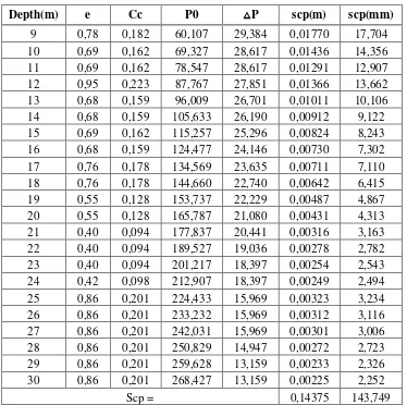
The amount of primary consolidation settlement calculated from a depth of 9.0m is provided in Table 3.
Table 3 Consolidation settlement
Depth(m) e Cc P0 △P scp(m) scp(mm)
9 0,78 0,182 60,107 29,384 0,01770 17,704 10 0,69 0,162 69,327 28,617 0,01436 14,356 11 0,69 0,162 78,547 28,617 0,01291 12,907 12 0,95 0,223 87,767 27,851 0,01366 13,662 13 0,68 0,159 96,009 26,701 0,01011 10,106 14 0,68 0,159 105,633 26,190 0,00912 9,122 15 0,69 0,162 115,257 25,296 0,00824 8,243 16 0,68 0,159 124,477 24,146 0,00730 7,302 17 0,76 0,178 134,569 23,635 0,00711 7,110 18 0,76 0,178 144,660 22,740 0,00642 6,415 19 0,55 0,128 153,737 22,229 0,00487 4,867 20 0,55 0,128 165,787 21,080 0,00431 4,313 21 0,40 0,094 177,837 20,441 0,00316 3,163 22 0,40 0,094 189,527 19,036 0,00278 2,782 23 0,40 0,094 201,217 18,397 0,00254 2,543 24 0,42 0,098 212,907 18,397 0,00249 2,494 25 0,86 0,201 224,433 15,969 0,00323 3,234 26 0,86 0,201 233,232 15,969 0,00312 3,116 27 0,86 0,201 242,031 15,969 0,00301 3,006 28 0,86 0,201 250,829 14,947 0,00272 2,723 29 0,86 0,201 259,628 13,159 0,00233 2,326 30 0,86 0,201 268,427 13,159 0,00225 2,252
Scp = 0,14375 143,749
Then the large decrease in total is the amount of instantaneous decrease in sand, clay and consolidation:
St=Si+Scp=44.3mm+144mm=188mm.
Figure 6 Relationship of Rib KSLL with Column P14
Calculation of the maximum load on Rib
Column = a1 x a2 = (100 x 70 ) cm2; Slab thick, t = 15 cm; Rib thickness, b1= 18 cm (the
red color)
hs = 300 cm; Rib thickness, b2 = 18 cm (the blue color); hk = 270 cm; = ⁄
√
[ ( ) ( ) (
) ( ) ( ) ] ( ( ) ( ))
[ ( ) ( ) (
) ( ) ( ) ] ( ( ) ( ))
=
= 114,28 cm Ix =441951270,4 cm4, and te is 182 cm (rounded)
Thickness the Rib = 0,41 m. Load maximum on Rib obtained 18547,486 kN, and P1 =
15101,211 kN. So, the total load on Rib P=Pmax – P1= –15101,211 = 3446,28 kN,
then the Stress in Rib is:
. Area F calculated = 13 m
2
Pmax of Column=7627kN on Column P14 (see Table 1), check:
; ,
the result is: 586,325 kN/m2 < kN/m2 …OK!
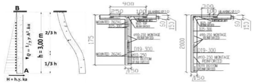
Rib and Plate Modeling
In the reinforcement needs analysis, calculate the loads and reactions that occur in the rib manually. Where the rib is assumed to be a cantilevered wall, with one free end and the other end wedged on the plate, the rib wedged on the plate will remain perpendicular to the floor slab. Rib resist lateral loads due to soil pressure, the maximum moment will occur on the pedestal pinch. Install the main reinforcement in the vertical direction rib, and the mounting reinforcing is horizontal direction.
Rib Reinforcement
Figure 10 Load and Deformation diagram of Rib Figure 11 Reinforcement Rib Interior and Exterior
Slab Reinforcement
Triangle shape of Slab
Support area Field Area
Figure 12 Support Condition Figure 13 Field Condition
On Support Area: Wu = 19,224 kN/m (has included its own load); Mu =Wu .L2/86,85 =19,224.106.42/86,85 =3,54.106 Nmm. With the addition 14%, then Mu = 4,04.106 Nmm, f’c = 25 Mpa; and fy = 350 MPa
d’(Concrete covers)= 40 mm. Used wiremesh, M10 with section area: AS=471,24mm2.
On Field Area: Mu =Wu .L2/50,85=19,224.106.42/50,85=5,46.106 Nmm; With the addition 14%, then Mu = 6,22.106 Nmm. Used wiremesh, M10 with section area: AS=471,24mm2
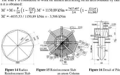
Reinforcement Slab an around column
f’c = 25 Mpa; and fy = 320 MPa; d’(Concrete covers) = 40 mm
Using yield line theory, the ultimate moment is obtained, due to maximum central load: Mu=
( ) =
( ) = 1150,89 kNm.
The load P is considered to work on limited area acting on an area bounded by radius = r, then it is obtained:
Calculation of Single Piling Capacity
The upper structural load is borne by the KSLL foundation, so the load on the pile is the foundation load of KSLL+workload obtained from the Structural modeling.
The upper structural load is borne by the KSLL foundation, so the load on the pile is the foundation load of KSLL+workload obtained from the Structural modeling.
The pile to be used is a "spun" pile as follows:
Outside diameter (DL) = 50 cm - Length of one pile segment = 6 m Inner diameter (DD) =32 cm - Concrete thickness = 9,0 cm Concrete Compressive Strength (f’c) = 60 Mpa - Steel yield Stress (fy) = 400 MPa
Nb end bearing pile = 20; Ab = 1/4 x 3,14 x 0,52 = 0,196 m2; Nav = 16+2+2+3+4+5+8+14+20 =
Decrease KSLL Combination Pile
Stiffness component Kr=11334,7 kN/m, and stiffness KSLL: Kp=1918 kN/m
The foundation structure of KSLL is always synergic with each other, with the soil compaction inside the ribs then the empty space will be filled so that the pile planting in the corners of the building is assumed like a table, each point requires 1 pile, but all are interconnected with each other to form a group of piles. Counting stiffness pile group: Kpsys=Kp√ =1918√ =5424kN/m, stiffness pile-raft: Kpr=4963,83 kN/m
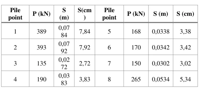
Proportion of load borne by the raft-pile: a = 0,03914, then βp =0,96, All points use each 1 pile then the magnitude of P1 = 1194 kN. Because of the burden at all points of the pile: P <
P1 then decrease at each point of the pile using the equation: S =
Table 4 Decrease KSLL Combination Pile Pile
Pile-cap dimensions: 1x1x0,5m,using the main reinforcement D25-125 and montage reinforcement D19-250.
CONCLUSION
1. The upper Building load is supplied to the foundation through column points, the total load of 181320.56 kN, and Pmax is in column P14. amounted to 7627.437 kN
2. The carrying capacity of the KSLL foundation on safety SF = 4 to resist settlement, yields qaKSLL = 1426KN / m2 with qult = 5703.28 kN / m2, after the addition of the pole to 14092 kN / m2.
3. Soft clay layer under sand layer still decrease consolidation.
4. The resulting decline in total (immediate+long term) on the foundation KSLL 18.8 cm, while the long-term decline in primary consolidation is only 14.4 cm, so it meets the requirements of <15 cm.
REFERENCES
[1] Education Media, 2018, Construction of Spider Nest Foundation, Building Image Engineering, SMK Panca Bhakti, Banjarnegara.
[2] Hidayatun M I, Juniwati A, Nurdiah E A, Damayanti R, Susilo N, 2018, Guidelines for Implementation of Building Construction, Office of PRKP and Cpta Karya of East Java. [3] Raharja R A, Sutjipto. 1984. Spider Nest Constructions. Surabaya: ITS Press.
[4] Raharja R A, 2015, Concrete Ribs Network for Sub Base Building Construction equipped with Vertical Insert and Implementation Method (KSLL Part 3), Indonesian Patent, the Directorate General of Intellectual Property.
[5] Samudro, G. and S. Mangkoedihardjo. 2006. Water equivalent method for city phyto structure of Indonesia. International Journal of Environmental Science & Technology 3 (3), 261-267.
[6] Sedayu, A. and S. Mangkoedihardjo. 2018. Performance Evaluation of Housing Contractor by Applying the Principles of Environmentally Friendly Infrastructure, International Journal of Civil Engineering and Technology, 9(4), 1014–1022.
[7] ACI Committee 318, 2011, Building Code Requirements for Structural Concrete and Commentary (ACI 318M-11), Fermington Hills-Michigan, USA, 503 pp.
[8] Astawa D Made, 2006, Concrete Structures 1, Modules Teaching, Department of Civil Engineering, UPN Veteran East Java, ISBN: 978-979-1005-21-0.
[9] Astawa D Made, Raka, IGP, Tavio, 2016, Shear Behaviorand Ductility Connections in Partial Pre-stressed Concete Beam-Column Reinforced Concrete Frame Structure Strory Building Due to Cyclic Lateral Loads, International Journal of BASR, ISSN: 2090-4304. [10] Bowles J E, Foundation Analysis and Design, Mc Graw-Hill. Inc, New York, USA. [11] Mina E, Kusuma R I, Nursoliha, 2017, Analysis of Bearing Capacity and Decrease of
KSLL Foundation in SKPD 1 Building. Foundation Journal, Volume 6 No. 1.
[12] Magfira, 2014. Alternative Planning of Spider-Nest Construction Foundation at Palu Grand Mall. University of Tadulako-Palu
[13] Purwanto S S., 2014, Construction Spiders Nest Soil Capacity Low-Rise Building Responsibility, Journal of Civil Engineering.12: 51-60.
[14] SNI 2847: 2013, Structural Concrete Requirements for Building", BSN, ICS 91.080.40. [15] SNI 1726: 2012, Earthquake Resilience Planning Procedures for Building Structures and
non-building, BSN, ICS 91.120.25: 91.080.01.
[16] Taulu L, Sosrodarsono S, Nakazawa K, 1983, Soil Mechanics and Foundation Engineering, Pradnya Paramita, Jakarta.
[17] Tomlinson M J, 1977, Pile Design and Construction Practice, ISBN 0 7210 1013 x, the Garden City Press Limited, Hertfordshire SG6 IJS.