ISSN Print: 0976-6308 and ISSN Online: 0976-6316
© IAEME Publication Scopus Indexed
THE TRUSS STRUCTURE SYSTEM
Fermanto Lianto
Department of Architecture, Tarumanagara University, Jakarta 11440, Indonesia
Rudy Trisno
Department of Architecture, Tarumanagara University, Jakarta 11440, Indonesia
Sidhi Wiguna Teh
Department of Architecture, Tarumanagara University, Jakarta 11440, Indonesia
ABSTRACT
In line with the development of architectural works that are increasingly
widespread and diverse in form, it requires the support of the right building structure system. The truss structure system as one of the commonly used structural systems has many variations and types. This study uses a literature study method on the truss structure system and discusses its application to several buildings to determine the various types of truss structure systems that exist. From the discussion it was found that the truss structure system was developed from simple basic forms by forming systems of truss frame structure, truss space structure and space frame structure.
Key words: Structure System, Truss Frame Structure, Truss Space Structure, Space Frame Structure
Cite this Article: Fermanto Lianto, Rudy Trisno and Sidhi Wiguna, the Truss Structure System, International Journal of Civil Engineering and Technology, 9(11), 2018, pp. 2460–2469
http://www.iaeme.com/IJCIET/issues.asp?JType=IJCIET&VType=9&IType=11
1. INTRODUCTION
In line with the development of architectural works that are increasingly widespread and diverse in form, it requires the support of the right building structure system. The architects seem to be competing to produce very diverse works. This is a challenge for structural system experts to realize these architectural works. With the help of sophisticated computer software, and the “courage” of structural experts to “get out” of the general rules, it allows the use of structural systems that can realize the “dreams” of architects with varied building forms [1].
that forms a united, then to hold a greater load the truss frame structure system forms a space to increase its strength, thereafter, to become a space frame structure that is able to stretch into a larger space as a wide span structure with free column in the center. The purpose of this paper is to know and understand the system of truss structures in buildings that are commonly used primarily for the function of the roof cover frame of the building.
2. MATERIAL AND METHODS
2.1. Methods of Study
This study uses a literature study method on frame structure systems and discusses its application to several buildings to find out the various types of existing truss structure systems that are grouped into systems of truss frame structure, truss space structure, and space frame structure.
2.2. TRUSS STRUCTURE SYSTEM
The building structure system is defined as a means to channel the burden of buildings from the top (roof) to the ground or as a collection of objects that have the same characteristics that are connected to each other in a certain way so that the whole system is able to function simultaneously in carrying and channeling loads horizontally or vertically [2].
To construct a building, it requires a truss structure that can carry all the burdens that work on the building and forward them to the supporting soil layer. One of the structure system that can be used is a frame structure system. The most basic and commonly used truss structure system is the truss frame structure system.
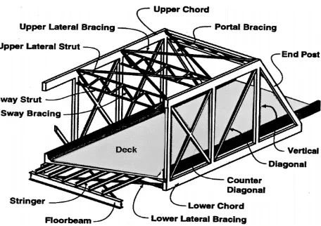
Andrea Palladio (1518-1580) an Italian architect, gave a description of the system of truss structures with a series of correct triangular patterns in carrying loads [2]. After that, the truss structure system began to be used in building constructions. Due to the increasing need for transportation facilities such as bridges, the potential of the truss structure system began to be developed in the nineteenth century (Figure 1).
3. RESULTS AND DISCUSSION
3.1. BASIC FORMATION OF THE TRUSS STRUCTURE SYSTEM
The main principle of the truss structure system is the arrangement of the rod forming a triangular configuration, because the triangular shape (triangulation) is a good or stable form in making a balance to direct the load bearing into a normal truss force, namely compressive and tensile loads. Whereas the load acting on the truss shape which is not triangular with the joint laying system causes the structure to become unstable and will result in relatively large deformations. If the triangular arrangement of the rod has a stable shape, then any triangle arrangement also forms a sturdy and stable structure system (Figure 2). In a stable structure, the external force causes a force acting on the rod which are the tensile force and compressive force [2].
Figure 2 Basic Principles of Triangulation and systems of truss joints.
Source: https://rebanas.com/gambar/images/rangka-batang-cremona-3-contoh-1-diketahui-konstruksi-gambar-jembatan, Retrieved on November 22, 2018 [4]
3.2. PRINCIPLES OF THE TRUSS STRUCTURE SYSTEM
3.2.1. Stability of the Truss Structure System
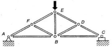
Each truss structure is a stable arrangement of triangular shape (Figure 3a) so that it cannot change shape or collapse. A collapse will occur if the truss structure is unstable (not forming a triangular pattern) under the burden (Figure 3b).
Figure 3 Basic Principles of Triangulation of Stable and Unstable Frame Structures. Source: Schodek, 2001:140-141 [2]
(a)The stable truss the frame occurs in a truss pattern that is entirely triangular
(b)Unstable rod frames occur in a triangular area (BDEF point), the truss
In a stable truss structure, deformation is relatively small and is associated with changes in rod length caused by forces arising in the rod as a result of external loads. The force acting inside the rod is a pure tensile and compressive force. While bending will not occur as long as the external force is at the vertex.
3.2.2. Truss Force
The forces acting on the trunks of the truss structure are distributed in each of the forming rod to the fulcrum, so that there is a rod that accepts the tensile force and compressive force.
The method used to determine the forces acting on the truss is based on a review of balance at the connecting point. In a simple trunk configuration, the nature of the force of the tensile or compressive can be determined by giving an idea of how the truss carry the load, for example by giving a picture of the shape of deformation that might occur when the structure is given a load [5].
3.2.3. Truss Design
The truss structure system has many variations in shape. Determining of rod configuration is the initial stage in designing the frame structure, before the rod style analysis process and determining the size of each structural element in a building so that the trunk configuration will be used in accordance with the shape of the designed building. Some forms of system configuration for truss structures are commonly used as shown in Figure 4. These configurations are influenced by external factors both in terms of structural and construction [6].
This truss structure system is very flexible to follow the shape of the building so that its use is very large and varies both in terms of the truss structure system, dimensions and profile of the rod and the building materials used. Likewise, a system of connections or joints between rods can be carried out in several ways such as the connection of bolts joints, weld joints or by using certain systems such as unistrut systems, mero systems and so on. In addition, the truss structure system can be displayed in its entirety as an element of building aesthetics by showing the honesty of its truss structure system.
3.2.4. The Height of Truss Structure
The total volume of the truss structure is strongly influenced by the height of the truss structure itself. The higher a truss structure, the greater the volume of the truss structure, and vice versa. In general, the angles formed by diagonal rod with horizontal lines range from 30o - 60o with an ideal angle of 45o. The following are simple guidelines for determining the height of the truss structure as an initial guideline (rule of thumb) but not as a final design (Table 1) [6]:
Table 1 Rule of Thumb for The Height of Truss Structure
Type of Truss Structure Height
Truss structure with relatively light loads
and close distances 1/20 from the long of the span The secondary collector rod frame that
carries the reaction produced by another truss frame
1/10 from the long of the span
The frame of the primary collector rod which carries a very large load, for example: truss frame which carries column loads from multi-storey buildings
1/4 or 1/5 from the long of the span
Source: Ariestadi, 2008:191 [6]
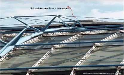
3.2.5. The Use of Cable Material for Pulling Rod in Truss Structure
Cable material elements are only capable of carrying tensile load. Physically this element is usually in the form of a small section of steel rod or wires. This element is unable to carry compressive loads (Figure 5). Elements that only carry a tensile load can have a smaller cross section compared to the elements that carry compressive loads.
Figure 5 The Use of Cable Material for Pulling Rod in Truss Structure Source: www. GreatBuildings.com, Retrieved on September 26, 2018 [7]
3.3. Types of truss structure SYSTEM
The truss structure system is a truss structure system made by connecting straight structural elements (rods) with joints (flexible joints) at both ends. The truss structure is composed of rod that experience tensile force and rod that experience compressive forces and are in a tensile and compressive force balance so that the construction is stable in holding the load.
3.3.1. The Truss Frame Structure System
The truss frame structure system is a series of rod that form one field and are in a tensile and compressive force balance that rests on a particular fulcrum (Figure 6, 7).
Figure 6 The Truss Frame Structure System
Figure 7 the Example of the Truss Frame Structure System
Source: https://lh3.googleusercontent.com/daJaGR2D7jrutvtimN7Oj2dNMJ_jXESiENbtjCrs-pv9pYYMf2vsM5Qmew_VLGwz3t9MoA=s122,Retrieved on September 26, 2018 [8]
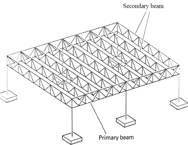
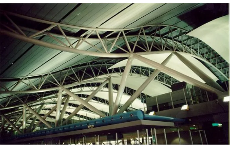
3.3.2. The Truss Space Structure System
Figure 8 The Truss Space Structure System
Source:https://lh3.googleusercontent.com/yVsIpecMfd1buI2xyNaHf4oAtmGbbHM9fS1DDJ078EuR VKKKuPeJtxbfvBQHIsvLmwF8qQ=s85, Retrieved on September 26, 2018 [8]
Figure 9 The Example of Truss Space Structure System, Kansai Airport, Osaka, Japan.
Source: https://www.barthe.net/jgallery/airport.htm, Retrieved on September 26, 2018 [9]
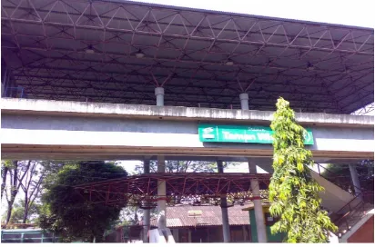
3.3.3. Space Frame Structure System
Figure 10 the Example of Space Frame Structure on the Roof of a Building in Taman Mini Indonesia Indah, Indonesia
Source: Private Document, 2014
The stability that exists in the pattern of triangular rod can be expanded into three dimensions. In the truss frame structure, a simple triangular shape is the basis, while the basic shape of the space frame structure is the tetrahedron (Figure 11).
The principles discussed in the analysis of truss frame structure generally can be applied to space frame structures. Stability is the main requirement where the forces arising in space frame structure can be obtained by reviewing the balance of space in the space rod pieces [6].
Figure 11 Detail Example of the Connection Joints in Space Frame Structure as Known as Unistruf System
Source: Schodek, 2001 [2]
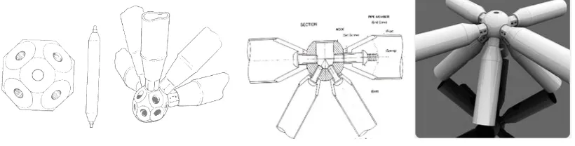
rod and another using a ball (ball joint) as a joint in the form of triangular modules, so that Space Frame is easy to install, mold, dismantle, and the implementation can be done quickly.
This system is called the mero system, which consists of pipe-shaped rod with bolts at the end and are connected to ball that has 16 holes to insert the rod.
This causes the mero system have a very wide variation for arranging the trunks in the ball to follow the desired shape of the building (Figure 12). Likewise, variations in the length of the stems will make the shapes that occur vary.
Figure 12 Detail Example of the Connection Joints in Space Frame Structure as Known as Mero System
Source: Schodek, 2001 [2] and https://www.pinterest.com/pin/386817055472550908/, Retrieved on September 26, 2018 [10]
4. CONCLUSION
The basis for the formation of a system of truss structure (especially joints or flexible joints in the truss) is the basic shape of the triangle (triangulation) of the arrangement of linear rod in the balance of tensile and compressive forces, forming a truss frame structure system. Then to increase the strength in carrying the external load and the length of the stretch (distance between supports), a truss structure is formed to create a space into a truss space structure. Furthermore, to further increase strength and stiffness, a system of truss space structure is combined into a space frame structure system that is able to cover a large space and free column in the middle (wide span structure).
REFERENCES
[1] Lianto, Fermanto. 2013, Building Structure System of Chinese Architecture, Past and Present, Civil Engineering Journal 4(1), pp. 63-80. March 2013. ISSN 2089-9513, http://untar.ac.id/pasca/publication/
[2] Schodek, Daniel L. 2001. Structure. 4th ed. Englewood Cliffs, NJ: Prentice Hall
[3] Chen, Wai-Fah & Duan, Lian. 2000. Bridge Engineering Handbook. Boca Raton: CRC Press
[4] https://rebanas.com/gambar/images/rangka-batang-cremona-3-contoh-1-diketahui-konstruksi-gambar-jembatan, retrieved on November 22, 2018
[5] Ariestadi, Dian. 2008. Teknik Struktur Bangunan. Jilid 3, Jakarta: Direktorat Pembinaan Sekolah Menengah Kejuruan. Direktorat Jendral Manajemen Pendidikan Dasar dan Menengah. Departemen Pendidikan Nasional
[6] Ariestadi, Dian. 2008. Teknik Struktur Bangunan. Jilid 2, Jakarta: Direktorat Pembinaan Sekolah Menengah Kejuruan. Direktorat Jendral Manajemen Pendidikan Dasar dan Menengah. Departemen Pendidikan Nasional
[7] www. GreatBuildings.com, Retrieved on July 2, 2011
[8] https://lh3.googleusercontent.com, Retrieved on September 26, 2016