by Kimmo and Tero Karvinen
Copyright © 2011 O’Reilly Media, Inc. All rights reserved. Printed in Canada.
Published by O’Reilly Media, Inc., 1005 Gravenstein Highway North, Sebastopol, CA 95472.
O’Reilly Media books may be purchased for educational, business, or sales promotional use. Online editions are also avail-able for most titles (my.safaribooksonline.com). For more information, contact our corporate/institutional sales department: 800-998-9938 or [email protected].
Development Editors: Brian Jepson and Brian Sawyer
Production Editor: Holly Bauer
Technical Editor: Joe Saavedra
Copyeditor: Rachel Monaghan
Proofreader: Jennifer Knight
Translator: Marko Tandefelt
Indexer: Ellen Troutman Zaig
Cover Designer: Mark Paglietti
Interior Designer: Ron Bilodeau
Illustrator/Photographer: Kimmo Karvinen
Cover Photographer: Kimmo Karvinen
Software Architect: Tero Karvinen
Print History:
March 2011: First Edition.
The O’Reilly logo is a registered trademark of O’Reilly Media, Inc. Many of the designations used by manufacturers and sellers to distinguish their products are claimed as trademarks. Where those designations appear in this book, and O’Reilly Media, Inc., was aware of a trademark claim, the designations have been printed in caps or initial caps.
Important Message to Our Readers: The technologies discussed in this publication, the limitations on these technologies that technology and content owners seek to impose, and the laws actually limiting the use of these technologies are con-stantly changing. Thus, some of the projects described in this publication may not work, may cause unintended harm to systems on which they are used, or may not be consistent with current laws or applicable user agreements.
Your safety is your own responsibility, including proper use of equipment and safety gear, and determining whether you have adequate skill and experience. Electricity and other resources used for these projects are dangerous unless used prop-erly and with adequate precautions, including safety gear. These projects are not intended for use by children. While every precaution has been taken in the preparation of this book,
O’Reilly Media, Inc. and the authors assume no responsibility for errors or omissions. Use of the instructions and suggestions in Make: Arduino: Bots and Gadgets is at your own risk. O’Reilly Media, Inc. and the authors disclaim all responsibility for any resulting damage, injury, or expense. It is your responsibility to make sure that your activities comply with applicable laws, including copyright.
This book uses Otabind™, a durable and flexible lay-flat binding.
Preface
. . .vii
1.
Introduction
. . .1
Building Philosophy . . . .1
Reusing Parts . . . 4
Buying Components . . . 6
Useful Tools . . . .7
Electronic Circuit Theory Review . . . .14
2.
Arduino: The Brains of an Embedded
System
. . .17
Why Arduino? . . . .17
Starting with Arduino . . . .18
Hello World with Arduino . . . .22
Structure of “Hello World” . . . .25
Arduino Uno . . . .27
Arduino Nano . . . .28
3.
Stalker Guard
. . .29
What You’ll Learn . . . .30
Tools and Parts . . . .30
Solderless Breadboard . . . .31
Jumper Wire . . . .33
Ping Ultrasonic Sensor . . . .33
Vibration Motor . . . .39
Combining Components to Make the Stalker Guard . . . .41
Making the Motor Vibrate. . . .41
4.
Insect Robot
. . .53
What You’ll Learn . . . .54
Tools and Parts . . . .54
Servo Motors . . . .55
Constructing the Frame . . . .59
Programming the Walk . . . .67
Avoiding Obstacles Using Ultrasound . . . .72
What’s Next? . . . .77
5.
Interactive Painting
. . .79
What You’ll Learn . . . .80
Tools and Parts . . . .80
Resistors . . . .81
LEDs . . . .83
Detecting Motion Using Ultrasonic Sensors . . . .85
Moving Images . . . .97
Installing Python . . . .97
Hello World in Python . . . 101
Communicating over the Serial Port . . . 103
Displaying a Picture . . . 107
Scaling an Image to Full Screen . . . 107
Changing Images with Button Control . . . 111
Gesture-Controlled Painting in Full Screen . . . 113
Animating the Sliding Image . . . 116
Connecting Arduino with Processing . . . 122
Processing Code for the Painting . . . 124
The Finished Painting . . . 128
Creating an Enclosure . . . 128
Building a Frame . . . 132
6.
Boxing Clock
. . .137
What You’ll Learn . . . 137
Tools and Parts . . . 138
Android Software Installation . . . 138
Creating a Boxing Clock in Android . . . 145
What’s Next? . . . 176
7.
Remote for a Smart Home
. . .177
What You’ll Learn . . . 177
Tools and Parts . . . 178
Hacking the Remote Control . . . 181
Controlling the Arduino from the Computer . . . 184
Creating a Graphical User Interface . . . 190
The Finished Remote Control Interface . . . 192
Creating an Enclosure . . . 195
8.
Soccer Robot
. . .199
What You Will Learn . . . 200
Tools and Parts . . . 200
Continuous Rotation Servos . . . 203
Modding a Standard Servo into a Continuous Rotation Servo . . . 207
Connecting the Arduino to the Bluetooth Mate . . . 211
Testing the Bluetooth Connection . . . 215
Building a Frame for the Robot . . . 217
Programming the Movements. . . 228
Controlling Movement from a Computer . . . 231
Steering with an Android Cell Phone . . . 234
The Accelerometer. . . 238
An Easier Approach to Bluetooth . . . 242
Controlling the Robot with Cell Phone Motion . . . 249
Completing the Soccer Robot . . . 253
What’s Next? . . . 262
A.
tBlue Library for Android
. . .263
Preface
In the early days, embedded systems were built primarily by engineers in a pretty exclusive club. Embedded devices and software tools were expensive, and building a functional prototype required significant software engineering and electrical engineering experience.
With the arrival of Arduino, the open source electronics prototyping platform, things are cheaper and easier. The hardware is inexpensive (around $30), the software is free, and the Arduino environment is designed for artists, design-ers, and hobbyists rather than engineering professionals.
The ultimate goal of this book is to teach you how to build prototypes using Arduino. We’ll offer just enough theory to help you apply your new skills to your own projects. You will also become familiar with the logic behind coding and components. We will explain every single line of code and tell you how each component is used. You will learn by completing actual projects, and the knowledge you gain will enable you to further develop your own ideas. Most books on embedded systems are either so specialized that you need to work within the particular field or too simplistic to be interesting. Books for be-ginners often just teach you to blindly follow instructions; here, we aim to pro-mote a deeper understanding and a skill set that can be applied more flexibly. Finally, this book is meant for readers who want to learn how to build proto-types of interesting gadgets, not for those who want to build a dental X-ray machine or a microwave oven. At the same time, you will be able to apply the techniques covered in the book to make prototypes of commercial device concepts.
Embedded Systems Are Everywhere
Most embedded systems are reactive systems, operating in a continuous in-teraction with their environment and responding within a tempo defined by that environment. This makes them a logical choice for tasks that must react immediately, such as a car braking system.
In some cases, it can be hard to tell whether a particular system should be classified as an embedded system or a computer. For example, cell phones are starting to include more and more features typically associated with comput-ers, but they still have much in common with embedded systems.
Why Should You Study Embedded Systems?
The world is already full of embedded systems. With reasonable effort, you can learn how to build one yourself. Turn inventions and ideas into inexpen-sive prototypes, automate your home by creating a fish-feeding device or con-trolling lighting from your computer, or build a remote-controlled surveillance camera for your yard that you can access via a computer located anywhere in the world. Artists can create interactive installations or integrate sensors into a game that you can control without touching a computer. Possible implemen-tations are endless.
During the 2000s, the DIY meme gathered more and more popularity, as is evident with the growth of MAKE Magazine and websites such as http://www .instructables.com. The Bay Area Maker Faire, an annual DIY festival, went from 22,000 attendees in its first year (2006) to more than double that amount (45,000) in its second year. And each year, Maker Faire attendance keeps growing.
Learning embedded systems is becoming even more appealing due to the growing interest in robotics. In a 2006 Scientific American article,* Microsoft founder Bill Gates predicted that robotics would be the next revolution within homes, comparing the current state of the robotics industry to the computing industry in the 1970s. Gates anticipates that robots will soon become a natu-ral part of a home, taking care of simple tasks such as vacuum cleaning, lawn mowing, surveillance, and food service. In addition, because robots can be con-trolled remotely from anywhere, we’ll be able to use them for telepresence— viewing, hearing, and touching people and things without even having to be present.
Intelligent Air Conditioning
The common use of embedded systems is not just the stuff of science fic-tion or future technology. It’s already here and pervasive in the home. Con-sider air conditioning. A smart air conditioning system adjusts itself based on measurements. How does it know when the air is thick or stale?
intelligent air control system has many benefits. It saves energy, because the air conditioning system doesn’t need to be used at full power all the time, and it makes working in such a space more comfortable, because there’s neither a constant draft nor stagnant air. The heating and air conditioning system at your own school or job likely functions on the same principles.
Sensors, Microcontrollers, and Outputs
Embedded systems include sensors, microcontrollers, and outputs. Sensors measure conditions within a physical environment, such as distance, accelera-tion, light, pressure, reflection of a surface, and motion.
The microcontroller is the brain of an embedded system. It’s a tiny computer, with a processor and memory, which means you can run your own programs on it. The Arduino microcontroller used in this book is programmed using a full-size computer via a USB cable, with sensors and outputs connected to the microcontroller pins.
Outputs affect the physical environment. Examples of outputs you’ll learn to control in this book include LEDs and servo motors. Output devices are some-times known as actuators.
Learn Embedded Systems in a Week
This book will teach you the basics of embedded systems in just one week, during which time you’ll build your first gadget. After that, you can move on to more complex projects and prototypes based on your own ideas. Within seven days, you will already be deep within the world of embedded systems. This goal can sound immense—at least, we felt it was impossible before we became familiar with contemporary development environments. But today, many projects that once felt impossible now seem straightforward.
The purpose of this book is to teach you how to build embedded systems, and we’ve left out any topic that does not support the practice of building proto-types. For example, we don’t cover history, movement of electrons, or complex electrical formulas. We believe it makes more sense to study these concepts after you are surrounded by your own homemade devices.
Classroom Use
We tested this book with actual students during a one-week, intensive course led by Tero Karvinen. By the end of the week, all the students in the course were able to build their own prototypes.
Feedback from the class included one common wish: a longer course with more theory. Hopefully, you will become equally hungry for more after you have learned how to build gadgets. We believe that learning electronic theory becomes more interesting after you have already built functional devices. For a complete book on electronics that begins at the beginning, see Charles Platt’s Make: Electronics (O’Reilly, http://oreilly.com/catalog/9780596153748).
What You Need to Know
Being able to use a computer is a prerequisite for completing the exercises in this book. You will need to know how to install programs and solve simple problems that often pop up during program and driver installation.
We’ve tested the instructions in this book in Ubuntu Linux, Windows 7, and Mac OS X. You should be able to implement the instructions relatively easily for other Windows systems or other Linux distributions.
Programming skills can be helpful but are not necessary for learning embed-ded systems. The particular programming language you know isn’t impor-tant, but being familiar with basic programming principles such as functions, if-then statements, loops, and comparisons is beneficial. It’s possible to learn programming along with learning about embedded systems, but this ap-proach could take more time. You might find it useful to consult a beginner’s book on programming.
High school–level electrical theory and knowledge of voltage, current, resis-tance, and circuits is sufficient. Have you already forgotten this? No worries— we will revisit basic electrical theory before starting the projects.
How to Read This Book
One of our goals is to provide information in an easily digestible form. By reading this book, anyone can learn how to build impressive-looking electronic devices. Instead of splitting the book into separate sections for techniques and code, we have attempted to combine the information within six projects. This way, you will learn new things bit by bit and can immediately test them in real situations.
The beginning of each project provides learning goals and a list of necessary parts. Before building a device, you can test each part individually; applying the components usually becomes much easier once you understand their core functions. It is useful to come back to these introductory sections later, as you incorporate things you have learned into your own new applications.
The projects are partitioned so you can test each part one step at a time. This way, it is easier to understand the function of each step and the relationships between different parts. This also helps ensure that once you have built a de-vice, you can easily troubleshoot any problems; if something doesn’t work, you can always go back to an earlier functioning phase and restart from there. There are examples of enclosures for several projects in this book. They are useful as teaching techniques for mechanical construction and give you ideas for how to make a demonstrable prototype relatively inexpensively. You are not obligated to follow the instructions literally. You might have different parts or a better vision for the look of your device.
Contents of This Book
This book includes two introductory chapters followed by six chapters with projects. As you move through the book, you’ll go from learning the basics of Arduino to completing projects with moving parts, wireless communication, and more:
Chapter 1, Introduction
This chapter explains prototyping, including an overview of the philoso-phy behind it, techniques, and tools.
Chapter 2, Arduino: The Brains of an Embedded System
This chapter familiarizes you with Arduino, the open source electronics prototyping platform used in every project in this book (except the Box-ing Clock in Chapter 6).
Chapter 3, Stalker Guard
In this chapter, you’ll learn how to use distance-finding sensors to detect when someone is trying to sneak up on you.
Chapter 4, Insect Robot
This chapter uses distance-finding sensors, servos, and spare parts to make an obstacle-avoiding robot.
Chapter 5, Interactive Painting
This chapter combines Arduino, your computer, and distance-finding sen-sors to create an interactive slideshow you can control with your hands. You’ll also learn about two languages for programming on the computer: Processing and Python.
Chapter 6, Boxing Clock
This chapter teaches you how to build a graphically rich timer clock on an Android phone. It will also serve as a primer for Chapter 8.
Chapter 7, Remote for a Smart Home
Chapter 8, Soccer Robot
This chapter combines a lot of what you’ve learned so far: Arduino, robot-ics, and cell phone (Android) programming. You’ll learn how to create a remote-controlled, soccer-playing robot. You’ll control it from your cell phone’s built-in accelerometer; simply tilt the phone to tell the robot to move or kick a small ball!
Appendix, tBlue Library for Android
The appendix presents tBlue, a lightweight library that makes it easy to communicate over Bluetooth between an Android phone and Arduino.
Conventions Used in This Book
The following typographical conventions are used in this book:
Italic
Indicates new terms, URLs, email addresses, filenames, and file extensions. Constant width
Used for program listings, as well as within paragraphs to refer to program elements such as variable or function names, databases, data types, envi-ronment variables, statements, and keywords.
Constant width bold
Shows commands or other text that should be typed literally by the user. Constant width italic
Shows text that should be replaced with user-supplied values or by values determined by context.
Using Code Examples
This book is here to help you get your job done. In general, you may use the code in this book in your programs and documentation. You do not need to contact us for permission unless you’re reproducing a significant portion of the code.
For example, writing a program that uses several chunks of code from this book does not require permission. Selling or distributing a CD-ROM of ex-amples from O’Reilly books does require permission. Answering a question by citing this book and quoting example code does not require permission. Incorporating a significant amount of example code from this book into your product’s documentation does require permission.
We appreciate attribution. An attribution usually includes the title, authors, publisher, copyright holder, and ISBN. For example: “Make: Arduino Bots and Gadgets, by Kimmo Karvinen and Tero Karvinen (O’Reilly). Copyright 2011 O’Reilly Media, 978-1-449-38971-0.” If you feel that your use of code examples falls outside fair use or the permission given above, feel free to contact us at
We’d Like to Hear from You
Please address comments and questions concerning this book to the publisher: O’Reilly Media, Inc.
1005 Gravenstein Highway North Sebastopol, CA 95472
(800) 998-9938 (in the United States or Canada) (707) 829-0515 (international or local)
(707) 829-0104 (fax)
We have a website for this book, where we list errata, examples, and any additional information. You can access this page at: http://oreilly.com /catalog/9781449389710. All code examples and programs are available on
http://BotBook.com.
To comment or ask technical questions about this book, send email to:
Maker Media is a division of O’Reilly Media devoted entirely to the growing community of resourceful people who believe that if you can imagine it, you can make it. Consisting of MAKE Magazine, CRAFT Magazine, Maker Faire, and the Hacks series of books, Maker Media encourages the Do-It-Yourself mental-ity by providing creative inspiration and instruction.
For more information about Maker Media, visit us online: MAKE: www.makezine.com
CRAFT: www.craftzine.com
Maker Faire: www.makerfaire.com
Hacks: www.hackszine.com
Safari
®Books Online
Safari Books Online is an on-demand digital library that lets you easily search over 7,500 technology and cre-ative reference books and videos to find the answers you need quickly.
With a subscription, you can read any page and watch any video from our library online. Read books on your cell phone and mobile devices. Access new titles before they are available for print, and get exclusive access to manu-scripts in development and post feedback for the authors. Copy and paste code samples, organize your favorites, download chapters, bookmark key sections, create notes, print out pages, and benefit from tons of other time-saving features.
Acknowledgments
Thanks to:• Juho Jouhtimäki • Marjatta Karvinen • Nina Korhonen • Mikko Toivonen • Marianna Väre
• Medialab, Aalto University School of Art and Design • O’Reilly Media
• Readme.fi
1
Introduction
This chapter will get you started building and
designing prototypes for embedded systems. You will learn basic principles that you’ll follow in Chapters 3 and 4 as you build the Stalker Guard and Robot Insect. Prototypes in this book are just the beginning. Once you know the techniques, you’ll be able to build prototypes for your own inventions.
Building Philosophy
When you break a programming problem down into smaller pieces, be sure to test and validate each piece as you go. If you don’t do this, you could find yourself wildly off track by the time you’ve gotten through a few pieces.
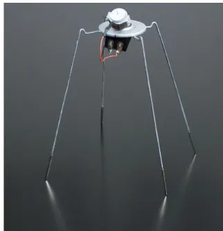
Prototype
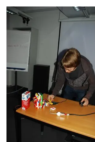
This book provides techniques for building prototypes, or test versions of a device. A prototype such as the one shown in Figure 1-1 provides a proof of concept—a concrete realization of a device’s intended functions.
Try to finish a functional prototype as quickly as possible. Once you’ve docu-mented a working prototype, you can build in improvements in later versions. You can make a working end result by stripping out unnecessary functions and taking shortcuts. If it makes testing quicker, use rubber bands and duct tape when you have to. Don’t try to optimize your code in the first version. It’s much easier to build an impressive version once the first prototype is fin-ished. Usually, you’ll find that many challenging problems you face in the pro-totype don’t even need to be solved for the final version. In the same way,
building a prototype can reveal new opportunities for development. type made of LegosFigure 1-1. Jari Suominen testing a
proto-IN THIS CHAPTER
Building Philosophy
Reusing Parts
Buying Components
Useful Tools
Having a prototype can also help you secure funding for your project. Who would you believe more: someone who talks about a walking robot, or some-one who has actually built some-one?
Start with Hello World
Starting a project with Hello World is usually a good idea, because it’s the simplest possible program. Typically, Hello World will print a row of text to a computer screen or blink an LED. It is used for testing to make sure the devel-opment environment works.
If your next, more complicated iteration doesn’t work, you can search for the cause of the problem within the added code. Hello World lets you know that the microcontroller, development environment, interpreter, and USB port all function correctly.
Build in Small Steps
Complex problems (see Figure 1-2, Figure 1-3, and Figure 1-4) are hard to solve, but you can usually make them easier by breaking them down into smaller pieces. You can then solve the problem one manageable piece at a time. A student of ours once built a burglar alarm after studying embedded systems for a week. The alarm buzzed whenever an infrared sensor detected move-ment. Users could log into the system wirelessly by presenting an ID in the form of a keychain. Once the system approved the login, the user could then move freely in the space without triggering an alarm.
Figure 1-3. Welding a robot hand
A project like this can sound quite complex to a novice, but it really consists of three clearly separate components (motion detector, buzzer, RFID reader). First, the student programmed and tested the motion sensor. That section was finished when the program could detect movement and sound the alarm. The three components of the system do not affect one another in any way, and the only unifying factor is the code. Program code can check with the motion detector to determine whether movement is present and, if so, it can switch How does Arduino say “hello” to the
world? By blinking an LED. You’ll learn more in Chapter 2.
Figure 1-2. Juho Jouhtimäki and Elise Liikala building a motion-sensitive soft toy
Test in Steps
“I wrote the code for a singing and dancing robot that can walk up stairs. The code is 30,000 lines long. I just tried compiling it, but it doesn’t work. Do you have any advice?”
Conduct testing as early as possible. If, for example, you build a walking robot, the first thing to test is whether you can make the servo motor move. The next test can make the servo move back and forth.
After you have tested the functionality of a specific version of code, save it separately from the version you are working on.
Revert to the Last Known Good Version
When you have developed your code into a confusing and nonfunctional state, the solution is easy. Go back to the last working version.
More specifically, go back to a working stage when the situation was already becoming confusing. This method removes the problem areas and lets you start over with a functional clean slate, helping you isolate what went wrong.
Read the Friendly Manual
RTFM is an old Internet acronym. (Actually, the F is not always friendly, so we usually stick with just RTM.) The point of the expression is that most answers are out there, written in a manual. When you’re surrounded by parts (see Figure 1-5), you're going to need answers.
Friends and students sometimes wonder how we know so much. How do we know the Arduino operating voltage or the way to install SSL encryption to the Apache web server?
Figure 1-5. Mikko Toivonen, surrounded by robots and microcontrollers
The answer is easy. You can find instructions for almost anything if you know where to look.
Computer DVD drives and hard drives can make great frames for robots, be-cause their covers are often made of lightweight, easily drillable, and sturdy material. You can also remove DC (direct current) motors and gears from DVD drives. Nowadays, there is more readily available computer junk than you can gather and store in your home. Educational institutions and corporations are particularly good sources, as they’re continuously throwing out old devices. Flea markets can also hold great finds. Mechanical typewriters deserve a spe-cial mention here. Though they are relatively hard to disassemble, they house an unbelievable amount of small springs, metal pieces of different shapes, and screws.
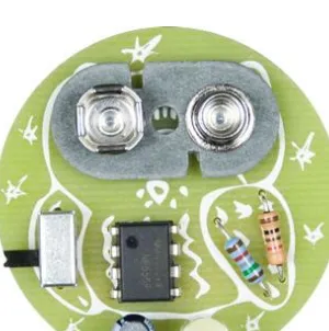
Disassemble devices as soon as you find them and then discard or recycle un-necessary parts. This way, you’ll avoid turning your home into a graveyard of retired devices, and more importantly, the parts will be immediately usable when you really need them. When you are searching for a suitable attachment piece for a servo, you probably don’t want to start a six-hour disassembly op-eration. Parts usually won’t find a new purpose until you’ve removed them from the original device, at which point inspiration might strike. You might even wonder how a specific “whatchamacallit” fits a new purpose so perfectly. When you begin working on some difficult new mechanism, think about where you might have seen something similar. You’ll often find everyday solutions to many problems. For example, parts purchased from bicycle or automotive shops can sometimes work in other projects. Figure 1-8 shows a hand with fingers that are moved with servo motors; every joint in each finger bends. The fingers were made by attaching sections of a steel pipe to a bicycle chain. They bend when a brake cable is pulled down. Typewriter parts welded to the opposite side of the structure pull the fingers back into a straight position.
Figure 1-8. Robot hand made of junk
Useful Tools
When building prototypes, you’re going to need some tools (Figure 1-10). The following sections cover the tools that we have found a consistent need for. They are not all mandatory, but depending on your own projects or needs, you may have a use for them in the future.
Hearing Protectors and Safety Glasses
When using power tools, you must cover your ears with proper hearing pro-tectors and wear safety glasses to protect your eyes from harmful flying debris and material fragments (Figure 1-11). Note that metal can fly forcefully, even when you’re cutting or bending with pliers.
Figure 1-11. Hearing protectors and safety glasses
Needlenose Electronics Pliers
You should immediately purchase good needlenose pliers (Figure 1-12), which can be used to grab small components and parts. The tip for the pliers should be sharp enough to fit into even the smallest of spaces.
Figure 1-10. Wire stripper and side-cutter pliers are sufficient for building prototypes on a prototyping board
Diagonal-Cutter Pliers
Diagonal-cutter (or side-cutter) pliers, shown in Figure 1-13, are used for cut-ting wires and are also suitable for other small cutcut-ting jobs. Always keep at least one set of side cutters in good shape, and use a secondary pair for tasks that cause more wear.
Metal Saw
A metal saw is a basic, functional tool for shaping and cutting metal (Figure 1-14). Keep a spare blade on hand to keep promising building processes from being interrupted by a broken blade.
Wire Strippers
Wire strippers are used to remove the plastic around a wire to expose a con-ducting metal within specific areas. Do not use your teeth to strip wires! It is much more expensive to fix dental enamel than to spend just a few dollars on good wire strippers. The adjustable wire strippers on the left side of Fig-ure 1-15 are much more useful than the multigauge model on the right, but they’re not as common.
Figure 1-15. Wire strippers
Figure 1-13. Diagonal-cutter pliers
Screwdrivers
You’ll need many different types of screwdrivers, especially when opening de-vices. Using the wrong screwdriver tip for a particular screw could destroy either the screw or the screwdriver and is just not worth the potential damage. The easiest and most economical thing to do is to buy a kit that comes with a handle and various attachable bits (Figure 1-16). Many electronic devices re-quire a Torx driver and can’t be opened with a flat- or Phillips-head screwdriver.
Alligator Clips
Alligator clips (Figure 1-17) can be useful for quickly connecting components and cables. They can also connect multimeter probes, enabling hands-free measurements.
Electric Drill
You’ll need an electric drill for many projects. A hammer drill, shown in Figure 1-18, is also suitable for drilling into concrete, but a rechargeable cordless drill is easier to handle.
A drill bit can break easily, especially when you’re drilling metal with thin bits, so you must wear eye protection when working with a drill. Always position the drill directly into the hole; drilling at an angle will bend the bit and cause it to break under rotation.
Figure 1-18. Electric drill
Figure 1-16. Screwdriver kit with a variety of bits
Leatherman
A portable handy tool such as a Leatherman (Figure 1-19) is useful during sev-eral phases of project building. In this case, it makes sense to invest in the name-brand tool rather than buying cheap imitations. A high-quality multi-purpose tool can withstand heavy use, and its individual parts function in the same way as separate tools.
Maker SHED sells an assortment of MAKE-branded Leatherman Squirt tools, such as the MAKE: Circuit Breaker Leatherman, a set of electronics tools that can fit on a keychain. See http://www.makershed.com/SearchResults. asp?Search=leatherman for more information.
Mini Drill
A mini drill (Figure 1-20) is not absolutely necessary, but it makes many tasks easier. Compared to an electric drill, a mini drill is lightweight and relatively precise to work with.
By using an appropriate bit, you can use a mini drill for drilling, sanding, sharpening, shining, cutting, and more. Of course, it doesn’t replace a normal drill, because it doesn’t have sufficient torque for drilling larger holes.
Figure 1-20. Mini drill
Headlamp
A headlamp (Figure 1-21) can be handy for focusing light in the direction you’re working. Additional light is useful to have, even in well-lit spaces.
Hot-Glue Gun
A hot-glue gun (Figure 1-22) can adhere items together quickly. The result-ing connection is not necessarily very strong, and glued items can bend away from each other, but it works sufficiently well in many prototyping phases. In addition, the fact that hot glue hardens quickly, and items glued with it can be (at least in theory) removed from each other relatively easily, can make the building process less stressful. Still, hot glue is not a replacement for Blu-Tack, and another downside is that if you’re unsuccessful in your first attempt to join items together using hot glue, you’ll usually need to scrape and shine the surfaces before trying again.
Nail Punch and Hammer
Drilling metal at home without a drill press can be quite challenging, espe-cially with smooth metal surfaces on which a bit can slide and go through the wrong spot. A nail punch (Figure 1-23, left) can fix this problem. It can create a small dent on the spot where you want to drill a hole, making drilling much easier.
A hammer is a useful tool in its own right, but it’s not always the right tool for the job. If you have something to dislodge or to set in place, look for a gentler tool first, so you don’t break your project into many little pieces. As Abraham Maslow said, “I suppose it is tempting, if the only tool you have is a hammer, to treat everything as if it were a nail.”
Figure 1-23. Nail punch and hammer
Figure 1-21. Headlamp
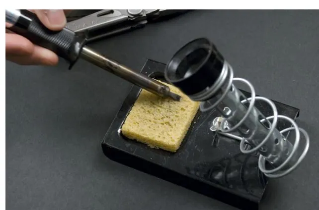
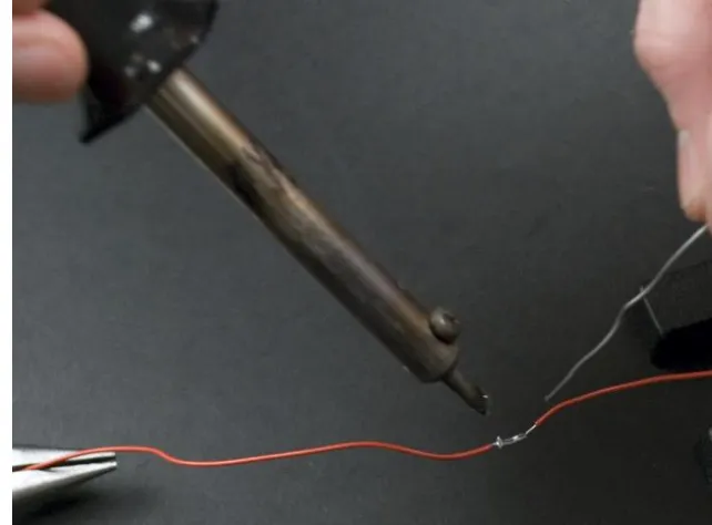
Soldering Iron
A soldering iron (Figure 1-24) joins metal sections of components together with molten metal (usually lead, but lead-free solder is available as well). The tip of a soldering iron must be sufficiently thin to enable precise attachment of small parts. Irons with a built-in thermostat are more expensive, but having the capability to adjust the temperature lessens the likelihood of destroying more sensitive components. You will learn the basics of soldering in Chapter 3.
Figure 1-24. Soldering iron
Multimeter
A multimeter (Figure 1-25) is used for measuring current, voltage, and resis-tance. You can use it to test a value of a resistor or whether two sections of a circuit are connected. You also can test the condition of a battery by measur-ing its voltage.
The multimeter shown in Figure 1-25 has two ranges for measuring voltage: DC (direct current) and AC (alternating current). All Arduino circuits in this book use direct current. The correct measurement range for voltage and re-sistance is the smallest possible range onto which measured readings can fit. A continuity test works technically in the same way as measuring a value of a resistor. Instead of displaying a resistance value, the continuity test beeps when an unrestricted flow of electricity is detected between two measure-ment probes.
Figures 1-26 and 1-27 illustrate some common uses for a multimeter. The Interactive Painting project in Chapter 5 covers measuring resistance in more detail.
Figure 1-26. The most common functions of a multimeter
Electronic Circuit Theory Review
We’ll end this chapter with just enough theory to get you started with the practice.
Voltage Creates an Electrical Current
Voltage refers to a difference in electrical potential between two parts of a circuit. For example, the terminals of a battery can have a 9-volt voltage between them.
If two parts of a circuit with different electrical charges are connected, volt-age potential creates a current flow. For example, current will start flowing through a lamp that is connected between the two terminals of a battery, causing the lamp to light up.
A unit of voltage is a volt (V). The Arduino microcontroller used in this book functions with a minimum 7V and maximum 12V power adapter (or it can be powered from a 5V USB connection). Voltages inside computers are within a similar range. US AC sockets provide 110 volts and European AC sockets pro-vide 230 volts.
A lamp will be brighter with a 9V battery than with a smaller 4.5V battery. Larger voltage creates a larger current. If a component is used with a voltage higher than what it is rated for, it will usually burn out. If you supply 5 volts to an LED that is rated for 2.4 volts, it will probably make a popping sound, release a little smoke, and cease to function. A running joke among electrical engineers and technicians is that once you’ve released the “magic smoke” inside an electronic component, you can’t put it back in.*
A Resistor Resists the Flow of Current
If a resistor is added between a lamp and a battery, the lamp will be dimmer. A resistor resists the flow of current.
All components create at least a bit of resistance. A filament of an incandes-cent light bulb is sufficient by itself to resist the current flow.
A resistor may be all that’s needed to avoid releasing the magic smoke inside an LED. For example, a 1 kOhm resistor is generally more than sufficient to protect a red LED. If you have the specifications for your LED, you can calculate the value of the resistor.
2
Arduino: The Brains of an
Embedded System
In this chapter, you’ll compile a program you have written onto an Arduino microcontroller, a small computer that acts as the brains of an embedded system. Arduino, an easy-to-learn hardware and software development environment and prototyping platform, is the foundation for the projects we’ll complete in upcoming chapters.
A microcontroller is a small computer with a processor and memory that controls the functions of many everyday devices. Some microcontrollers are designed to connect easily to a computer for programming for specialized purposes. Arduino is an example of one of these easy-to-program microcontrollers. Microcontrollers make it easier to build electronic devices because you can control their functions via code. Microcontrollers can control and interpret forms of both input and output. For example, you can flicker an LED by con-necting it to a specific Arduino pin with code that instructs it to switch the current on for one second and then off for one second. The LED is an example of an output, which you could then control using a sensor, button, switch, or any other form of input. Naturally, most programs do many other, more so-phisticated tasks. Microcontrollers enable us to solve quite complex problems step by step.
Why Arduino?
The most suitable microcontroller choices for a beginner are Basic Stamp and Arduino. Basic Stamp has existed since the early 1990s and has become popu-lar among hobbyists. It uses the Basic programming language, which is easy to use but somewhat limited compared to the C language used by Arduino.
IN THIS CHAPTER
Why Arduino?
Starting with Arduino
Hello World with Arduino
Structure of “Hello World”
Arduino Uno
Functionally, Arduino is quite similar to Stamp, but it solves many problems that Stamp has traditionally faced. One significant feature for hobbyists is Arduino’s lower cost: the basic Arduino starting package is approximately a quarter of the price of a comparable Stamp package. And, despite its cheaper price, Arduino has a more powerful processor and more memory.
Arduino is also smaller than Stamp, which is beneficial in many projects. The Arduino Uno model (see Figure 2-1, left) is slightly smaller than the Stamp, but the tiny Arduino Nano (Figure 2-1, right) is about the same size as the Stamp
module that sits on the Stamp board (just above the serial port in Figure 2-2). For comparison, Figure 2-2 shows the Stamp and the Nano next to each other.
Figure 2-1. Arduino Uno (left) and Arduino Nano (right) Figure 2-2. Basic Stamp (left) and Arduino Nano (right)
One final asset is that the Arduino programming environment is based on open source code and can be installed on Windows, Mac OS X, and Linux.
Starting with Arduino
Arduino is available in a few different models. This book covers the aforemen-tioned Arduino Uno and Arduino Nano. Uno is an inexpensive (around $30) and sturdy basic model, and is the most current version of the board. It was released publicly in September 2010 and is the successor to the Arduino Dieci-mila and Arduino DueDieci-milanove. Nano is significantly smaller, but more fragile and slightly more expensive ($35). Both models are described in a bit more depth at the end of this chapter.
First, you have to buy an Arduino and a compatible USB cable. Uno and Nano communicate to your computer via USB (for uploading new programs or send-ing messages back and forth). They can also take their power over USB. Uno uses a USB-B cable and Nano uses a Mini-B, and each connects to the computer with a USB-A male connector. All three connectors are shown in Figure 2-3. Chapter 8 includes a project that
Figure 2-3. Arduino USB cables: Mini-B, USB-A, and USB-B
Installing Arduino Software
Next, you need to install the Arduino development environment for your op-erating system and compile the first test program. This “Hello World” code is the most important part of getting started with a new device. Once you are able to compile simple, light-blinking code in Arduino, the rest is easy.
The examples in this book were tested with version 0021 of the Arduino devel-opment environment. If you decide to use some other version, the installation routine might differ. If you are using an operating system other than Windows, Ubuntu Linux, or Mac OS X, or an Arduino other than Uno or Nano, look for installation instructions at http://arduino.cc/. And remember that you will find all complete code examples, links, and program installation packages at
http://BotBook.com/.
Windows 7
Here’s how to get up and running under Windows 7:
1. Download the Arduino development environment from http://arduino.cc/ en/Main/Software and unzip it to the desired folder by clicking the right button and selecting “Extract all.”
2. Connect the USB cable to your computer and to the Arduino’s USB port. The Arduino LED should light green.
3. Windows will search for and install the necessary drivers automatically. It notifies you when the installation is complete. If Windows does not locate the driver:
b. Locate Arduino Uno in the list of devices (it should be in the section called Other Devices). Right-click it and choose Update Driver Software. c. Choose “Browse my computer for driver software.”
d. Navigate to the Arduino folder you extracted, select the drivers subdi-rectory, and press Next.
e. If prompted to permit the installation of this driver, choose “Install this driver software anyway.”
When the driver is successfully installed, you’ll see the dialog shown in Figure 2-4.
Figure 2-4. Drivers installed
Windows XP
In general, installation for most Windows XP programs is pretty similar to Win-dows 7, but Arduino is an exception. If you have XP, start by downloading the Arduino development environment, extracting the file to a location on your computer, and connecting the Arduino to your computer as described in the previous section. Then follow these additional instructions:
1. Windows opens the Found New Hardware Wizard.
3. Deselect the checkbox in “Search removable media” and check the box “Include this location in the search.” Navigate to the Arduino folder you extracted, select the drivers subdirectory, and press Next. If you are using an older model of Arduino, or the Nano, you may need to choose the
drivers/FTDI USB Drivers subdirectory instead. 4. Click Finish.
Ubuntu Linux
Though you can install Arduino on Ubuntu and other Linux environments using graphical user interface tools, the following steps use the Terminal (Figure 2-5) to simplify the instructions.
Open the Terminal by choosing Applications→Accessories→Terminal. The dollar sign at the beginning of the following command lines is the command prompt created by the computer; do not type the dollar sign, just the charac-ters that follow it.
We tested this installation process with Ubuntu 9.04, but it should also func-tion (with minor alterafunc-tions) with other versions.
Figure 2-5. Command line
Start using the universe program repository, which includes free, open source programs, with publicly available source codes:
$ sudo software-properties-gtk --enable-component=universe
When asked by sudo, type your password. The command after sudo will be executed using root user privileges.
Update the available software list: $ sudo apt-get update
Now it’s time to install dependencies: all the programs the Arduino develop-ment environdevelop-ment requires to function, including Java (openjdk) and pro-gramming tools for the AVR chip gcc-avr, avr-libc, and avrdude. New 64-bit computers also require the 32-bit compatibility library ia32-libs.
$ sudo apt-get install --yes gcc-avr avr-libc avrdude openjdk-6-jre $ sudo apt-get install --yes ia32-libs
Next, download and open the Arduino development environment from the official Arduino home page (http://arduino.cc/en/Main/Software), where you’ll find two packages: “Linux (32bit)” and “Linux (AMD 64bit).” Newer computers are based on 64-bit technology. If you don’t know which package to down-load, use the uname-m command to determine whether your computer is a newer 64-bit model (x86_64) or an older 32-bit model (i386).
Uncompress the software package you downloaded (this will create an arduino-version directory under your current working directory):
$ tar -xf ~/Downloads/arduino-*.tgz
Start the Arduino development environment. Because you will execute the command from a specific folder, define the whole path to that folder:
$ ./arduino
The Arduino development environment will start.
Mac OS X
Here’s how to get up and running under Mac OS X:
1. Download the Arduino development environment from http://arduino.cc/ en/Main/Software and open the .dmg file.
2. A new Finder window appears with three icons (Arduino, a link to your Applications folder, and the FTDI USB serial driver package).
3. Drag the Arduino icon to your Applications folder.
4. If you are using a version of Arduino prior to the Uno, install the FTDIUSB-SerialDriver package.
5. When you connect the Arduino, you may see the message “A new net-work interface has been detected.” Click Netnet-work Preferences and then click Apply. You can close the Network Preferences when you are done.
Hello World with Arduino
Now you’re ready to upload your first Arduino program. Open the Arduino development environment:
Windows
Linux
Change directory to the Arduino folder and run Arduino: $ cd arduino-0021
$ ./arduino Mac OS X
Double-click the Arduino icon (you’ll find it inside the Arduino folder). Select Tools→Board→Arduino Uno, as shown in Figure 2-6. If you are using a different model of Arduino, select it instead.
Figure 2-6. Arduino board selection
Select File→Sketchbook→Examples→1. Basics→Blink. This example code flashes the LED on the Arduino pin 13 (the Uno includes an onboard LED con-nected to pin 13).
Determine which serial port Arduino is using: Windows
Figure 2-7. Determine the correct port
Linux and Mac OS X
With the Arduino unplugged from your computer, select Tools→Serial Port in the Arduino development environment, and observe the list of se-rial ports listed (such as /dev/ttyUSB0 in Linux or /dev/tty.Bluetooth-Modem
in Mac OS X). Dismiss the menu by clicking elsewhere onscreen.
Plug the Arduino in and choose the same menu options again (Tools→Serial Port). Observe which serial port appeared. You’ve figured out which serial port your Arduino is using.
In the Arduino development environment, select Tools→Serial Port and choose the port you found in the previous step.
Click the icon with the right-pointing arrow in a square box, or choose File→“Upload to I/O Board.” The Arduino transmission lights will flash briefly, and you should see the message “Done uploading.”
Now you should see the yellow LED labeled L on the Arduino board flashing (see Figure 2-8). This means you have successfully installed the Arduino devel-opment environment and uploaded your first Arduino program to the micro-controller. If the light is not flashing, follow the instructions again to see where the installation went wrong. You cannot proceed if this does not work. If you continue to have problems, see the online Arduino troubleshooting guide at
Figure 2-8. The LED on pin 13
You might want to come back to this section and run through these steps if you have problems working with Arduino in the future; the Blink example is a good test to ensure that Arduino is working. If the LED does not flash, it’s a good time to make sure the cord is plugged in, or determine whether your computer or the Arduino is having problems. Once you establish that some-thing as simple as blinking an LED works, it will be easier to solve the more complex problems later.
Structure of “Hello World”
You just took an important step by running the “Hello World” of Arduino: Blink. The program blinks an internal LED on the Arduino. If you can get the LED to blink, you can be confident that you can compile and upload programs to Arduino.
All Arduino programs have a similar structure. Since Blink is a simple program, it is easy to understand the program structure by examining it.
Here is the source code for Blink, which comes with Arduino but is offered here with our commentary:
/* Blink 1
Turns on an LED on for one second, then off for one second, repeatedly.
*/
void setup() { 2
// initialize the digital pin as an output.
// Pin 13 has an LED connected on most Arduino boards: pinMode 3 (13, OUTPUT 4); 5
void loop() { 6
Let’s review each section of the code.
1 A slash followed by an asterisk (/*) opens a block of comments (they
are ended by a */). Two forward slashes (//) indicate that the rest of the line is a comment. Comments consist only of information for the user; Arduino does not react to them. Comments will be removed during the compiling process, and they are not uploaded into the Arduino. This comment states the title and purpose of the program (known as a sketch). Most comments describe the purpose of a specific line or block of code.
2 The setup() function executes once in the beginning of a program,
where one-time declarations are made. The setup() function will be called automatically immediately after the Arduino is powered or has been programmed. Calling a function consists of a return value of a func-tion (void), the name of the funcfunc-tion (setup), and a list of parameters in parentheses. This function does not take parameters, so there is nothing inside the parentheses. This function does not return values, so its type is void (empty). When calling a function, commands are listed within a block of code, which is enclosed in curly braces ({}).
3 This setup() function includes only one command, which sets the pin
connected to the LED into output mode. It calls the pinMode() function, which is defined in the Arduino libraries.
4 OUTPUT is a constant defined within Arduino. When using digital pins
on an Arduino, you must always declare them to be in either OUTPUT or INPUT mode.
5 As is required by the C language (which Arduino is based on), a line ends
with a semicolon.
6 The majority of the execution time of the program will repeat the loop()
function. The loop() function is called automatically (and repeatedly) after the setup() function finishes.
7 To address a digital pin that has been set to be an OUTPUT, we use the
digitalWrite() function. Set digital pin 13 on HIGH (which means +5V). Digital pin 13 is unique in that Arduino has a built-in LED and resistor attached to it, specifically for debugging purposes. The LED will light up. The pin remains on HIGH until we address the pin with another call from digitalWrite().
8 Wait 1,000 milliseconds (1,000 one-thousandths of a second, totaling
one full second). The LED is lit all the time.
9 Switch the pin off (LOW) and wait again for a second. This is the last
com-mand in the loop() function, which means that the execution of the loop() function ends.
The program will call the loop() function over and over again automatically. The execution will continue from the first line of the loop() function, which sets the LED (ledPin) on HIGH. The execution of the program continues by repeating the loop() function until it is stopped by disconnecting power from the Arduino.
Arduino Uno
The Arduino Uno (Figure 2-9) is a good choice for your first Arduino. It is inex-pensive and reliable. The Uno will use the power provided by the USB cable when the cable is connected to a computer. If necessary, it can also be pow-ered by an external power supply such as a battery. When you upload code from your computer, the program is saved to the microcontroller itself. This means you can disconnect the Arduino and allow it to function as an indepen-dent device.
The Uno’s pins have female headers that enable you to connect wires without soldering. This speeds up the building of simple prototypes but is not a very good longer-term solution, because cables can fall off relatively easily.
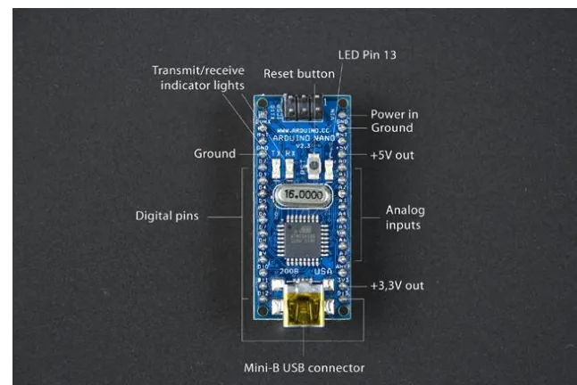
Arduino Nano
The Arduino Nano (Figure 2-10) is considerably smaller than the Uno men-tioned earlier. It also has pins that you can connect straight onto a prototyping breadboard. These allow you to easily construct even quite complex circuits without soldering.
Figure 2-10. Arduino Nano
Nano is more expensive and sensitive than Uno. For example, a certain kind of short circuit will break Nano permanently. Another downside is that it is harder to read the markings on the pins, making it easier to misplace wires. With the addition of a mini breadboard and retractable USB cable, the Arduino Nano becomes part of a handy travel pack (see Figure 2-11).
The Arduino Pro Mini (see Chapter 8 for more details) is even smaller than the Nano. It does not include a USB-serial adapter onboard, so you need to use a separate USB-serial adapter to program it. However, it is extremely small and lightweight, and comes in low-power variants, which makes it an ideal choice for projects where weight is a significant issue, such as airborne drones or remote-controlled vehicles.
Now you know the basics to get started with your first project. In the next chapter, you will try Arduino in practice while building the Stalker Guard.
3
Stalker Guard
In this project, you will build a Stalker Guard (Figure 3-1), a simple alarm device that measures the distances of objects behind you and vibrates when something comes too close (see Figure 3-2). You will also learn a program you can easily modify for other projects that works by monitoring data sent by a sensor and reacting when specific conditions are filled.
Over the course of this project, you will learn the basics of Arduino program-ming, distance measurement with ultrasonic sensors, and motor control. The Stalker Guard can be easily customized into new variations by changing the values of the ultrasonic sensor, replacing the sensor with another one, or replacing the motor with, say, a speaker. With little effort, you can develop the circuit further—for example, by turning it into a height meter.
IN THIS CHAPTER
What You’ll Learn
Tools and Parts
Solderless Breadboard
Jumper Wire
Ping Ultrasonic Sensor
Vibration Motor
Combining Components to Make the Stalker Guard
Making the Motor Vibrate
Providing Power from a Battery
What’s Next?
Before starting the project, you’ll need to install the Arduino development environment and make sure you can run the “Hello World” program from Chap-ter 2. The project is organized in steps, so you can always return to the previous step if you find that something isn’t functioning correctly. Remember that you can download the complete code examples for each stage at http://BotBook .com/ or http://examples.oreilly.com/0636920010371, which allows you to test their functions before reading the individual descriptions of each program.
Figure 3-2. The Stalker Guard in action
What You’ll Learn
In this chapter, you’ll learn how to:• Measure distance using the PING))) ultrasonic sensor • Use a motor
• Apply the principles of Arduino programming • Power Arduino from a battery
Tools and Parts
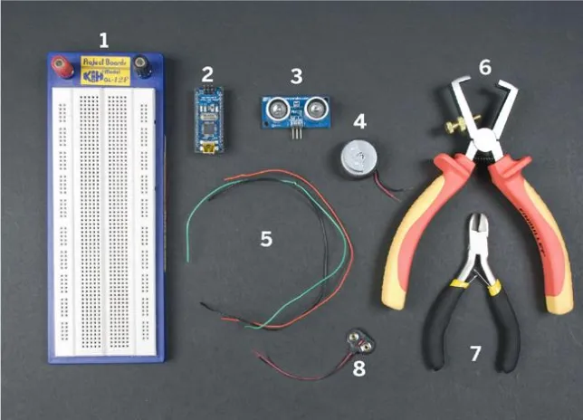
You’ll need the following tools and parts for this project (Figure 3-3).
Manufacturer part numbers are shown for: • Maker SHED (US: http://makershed.com): SHED
• Element14 (International and US; formerly Farnell and Newark, http://element-14 .com): EL14
Figure 3-3. Parts and tools used in this chapter
1. Solderless breadboard (SHED: MKEL3; EL14: 15R8319; SFE: PRT-00112). 2. Arduino Nano (SHED: MKGR1; http://store.gravitech.us; or http://store
.gravitech.us/distributors.html).
3. PING))) ultrasonic sensor (SHED: MKPX5; http://www.parallax.com/Store/). 4. Vibration motor (SFE: ROB-08449). If you can’t find a vibration motor
any-where, you can replace it with an LED. These motors can also often be salvaged from broken cell phones.
5. Jumper wires, at least three colors (SHED: MKEL1; EL14: 10R0134; SFE: PRT-00124).
6. Wire strippers (EL14: 61M0803; SFE: TOL-08696). 7. Diagonal cutter pliers (EL14: 52F9064; SFE: TOL-08794). 8. 9V battery clip (EL14: 34M2183; SFE: PRT-00091).
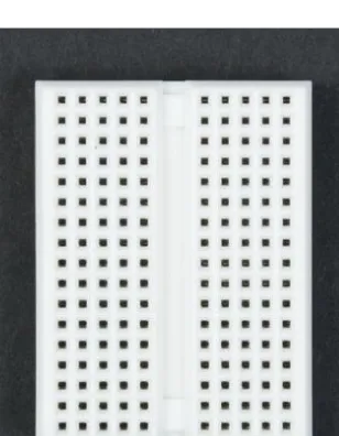
Solderless Breadboard
To prototype circuits without soldering, you can use a solderless breadboard. To connect components, you’ll push their legs (leads) into holes on the board. In Figure 3-4, two pairs of bus strips (power rails) are connected horizontally
Note the power terminals at the left end of the breadboard in Figure 3-4. These are useful, but you won’t find them in every breadboard. If your breadboard does not have power terminals, you can push power leads into any of the holes in the ap-propriate horizontal row to provide power to all the other leads along that row. We won’t use power terminals in this project.
Figure 3-4. The holes in the prototyping breadboard are connected to each other by vertical rows; bus strips for power are connected horizontally
Figure 3-5 shows the breadboard with its bottom cover removed (don’t do this to your breadboard, as it tends to damage it) so you can see more clearly how the rows are connected to each other.
Figure 3-5. View of the bottom of the prototyping breadboard; metal plates conduct current from hole to hole
So how would you connect the Arduino Nano’s D5 (digital pin 5) pin to the second wire of a motor? Insert the Arduino into the middle of the prototyp-ing board (also known as the “gutter”), so that it is straddlprototyp-ing the vertical rows between both sides of the Arduino legs. This prevents us from short-circuiting the opposite side legs of the Arduino.
Push the Arduino into the board so that the Arduino’s D5 pin is connected to each hole of the strip on the same side of the gutter (highlighted in Figure 3-9, which appears later in this chapter). Then simply insert the motor wire in the hole next to the Arduino D5 pin. Now the motor wire and Arduino pin D5 are connected to each other.
It’s always a good idea to begin a project by building circuits on a prototyping breadboard. Once you’re sure that a project functions correctly, you can then consider a more permanent place for it. Even in the next stage, you don’t need to solder things together. For example, you can leave the more expensive parts, such as the Arduino itself, on a smaller prototyping breadboard (Figure 3-6). This way, you can easily use it in other projects and then put it back in its original place.
One negative aspect of ultrasonic sensors is their relatively high price ($30 at the time of this writing).
Measuring Distance with the Ping Ultrasonic Sensor
To begin creating the program, first connect the Arduino and upload the Blink code shown in Chapter 2. This brief exercise is always useful when you’re start-ing a new project, because it confirms that the development environment still functions properly.Insert the Arduino Nano in the middle of the prototyping breadboard, as shown in Figure 3-9. Pressing the Nano in all the way might require a bit of force, so be careful not to bend its pins. Next, connect the PING))) Ultrasonic Sensor to the Arduino by inserting it into the prototyping breadboard and connecting the Arduino pins to its pins with jumper wires.
Figure 3-9. Arduino Nano on a breadboard
Figure 3-11 shows how the breadboard should appear; Figure 3-12 shows this circuit’s schematic.
Figure 3-11. A connected ultrasonic sensor Figure 3-12. Schematic for the ultrasonic sensor circuit
Distance-Measuring Program
Open the Arduino development environment and connect the Arduino to the computer’s USB port. Feed the following code to Arduino by saving it into a new sketch and clicking Upload. This code is based on the Ping example that comes with the Arduino IDE (File→Examples→6. Sensors→Ping).
/* Ping))) Sensor
This sketch reads a PING))) ultrasonic rangefinder and returns the distance to the closest object in range. To do this, it sends a pulse to the sensor to initiate a reading, then listens for a pulse to return. The length of the returning pulse is proportional to the distance of the object from the sensor.
The circuit:
* +V connection of the PING))) attached to +5V * GND connection of the PING))) attached to ground * SIG connection of the PING))) attached to digital pin 2
http://www.arduino.cc/en/Tutorial/Ping
created 3 Nov 2008 by David A. Mellis modified 30 Jun 2009 by Tom Igoe
modified Nov 2010 by Joe Saavedra
*/
const int pingPin = 2; 1
void setup() {
Serial.begin(9600); 3 }
void loop() {
pinMode(pingPin, OUTPUT); 4 digitalWrite(pingPin, LOW); delayMicroseconds(2); digitalWrite(pingPin, HIGH); delayMicroseconds(5); digitalWrite(pingPin, LOW);
pinMode(pingPin, INPUT); 5 duration = pulseIn(pingPin, HIGH);
distanceInches = microsecondsToInches(duration); 6 distanceCm = microsecondsToCentimeters(duration); Serial.print(distanceInches); 7
Serial.print("in, "); Serial.print(distanceCm); Serial.print("cm"); Serial.println();
delay(100); }
long microsecondsToInches(long microseconds) {
return microseconds / 74 / 2; 8 }
long microsecondsToCentimeters(long microseconds) {
return microseconds / 29 / 2; 9 }
Let’s look at what the code does:
1 This constant won’t change. It’s the pin number of the sensor’s output. 2 Establish variables for the duration of the ping and the distance result in
inches and centimeters.
3 Initialize serial communication at 9,600 bits per second.
4 The PING))) is triggered by a HIGH pulse of 2 or more microseconds. Give
a short LOW pulse beforehand to ensure a clean HIGH pulse.
5 The same pin is used to read the signal from the PING))): a HIGH pulse
whose duration is the time (in microseconds) from when the ping is sent to when its echo off an object is received.
6 Convert the time into a distance.
micro-2 Execute the setup() function only once, in the beginning. This function
does not return any value; therefore, its type is empty (void).
3 Switch pin D5 to an OUTPUT state. An Arduino pin can be set either as an
output or an input. Because you would like to send power to the motor, choose OUTPUT.
4 Turn on power to the D5 pin. The pin remains HIGH unless we set it to
LOW, which makes the motor rotate continuously.
5 The tasks your sketch performs will be written within the loop()
func-tion. An ordinary Arduino sketch spends most of its time repeating a loop. Since there is nothing to do in the loop() function, it is empty.
Combining Components to Make
the Stalker Guard
Now you know how the necessary components work by themselves. Next, you will combine them to create the Stalker Guard.
First, connect the circuits for the motor and the ultrasonic sensor. Figure 3-17 shows them connected on the breadboard, and Figure 3-18 shows the sche-matic. Once you’ve connected them, it is wise to retry the code tested earlier for both devices, so you are testing only a single component at a time. This way, you ensure that you built the circuit correctly, which also makes trouble-shooting easier in later stages.
Figure 3-17. Vibration motor and ultrasonic sensor connected Figure 3-18. Vibration motor and ultrasonic sensor schematic
Making the Motor Vibrate
Now you will combine both of the sketches. To find out when a target is close, we’ll make the vibration motor react when the distance to a target is below the specified limit:
/*
stalkerguard.pde - Shake if something comes near (c) Kimmo Karvinen & Tero Karvinen http://botbook.com
updated 2010 – Joe Saavedra; based on code by David A. Mellis and Tom Igoe */
const int pingPin = 2; const int motorPin = 5;
long int duration, distanceInches, distanceCm; int limitCm = 60; 1
duration = pulseIn(pingPin, HIGH);
distanceInches = microsecondsToInches(duration); distanceCm = microsecondsToCentimeters(duration);
checkLimit(); 2
digitalWrite(motorPin, LOW); }
This program combines the earlier ultrasonic sensor and vibration motor code to determine whether the readings from the ultrasonic sensor are less than the defined threshold distance. If the distance is shorter, the motor will switch on.
1 Add this variable to define the distance; when something gets this close,
we will start the motor.
2 Now that we have our current distance calculated, call the checkLimit
function.
3 If the distance is shorter than the defined threshold distance, switch on
• Posture Watchdog: a device that warns you if you are leaning too close to your computer screen
• A distance-measuring device
• A robot that vibrates when you get close to it (see Figure 3-21)
Figure 3-21. Vibrating robot, still lacking the ultrasonic sensor
Making an Enclosure
In the following sections, we’ll outline one way to enclose the Stalker Guard to attach it to your waist and use it without wires. You don’t need to follow these instructions exactly. Use them as a guideline and supply your own creativity and available parts.
Utilizing an Ammo Pouch
As a starting point, we took an old ammo pouch purchased from an army surplus store (Figure 3-22). The pouch is made of rubber-coated linen fabric, which is relatively easy to perforate and cut. And its price—one euro—did not damage our budget.