International Review of Mechanical Engineering (I.R.E.M.E), Vol. 5, N.2 Special Issue on Heat Transfer, February 2011
Modeling and Simulation of Temperature Generated on
Workpiece and Chip Formation in Orthogonal Machining
Hendri Yanda, Jaharah A. Ghani, Che Hassan Che Haron
Abstract – Experimental investigation in machining operation for the temperature
generated on workpiece, chip formation and cutting tool are difficult, time consuming and costly to carry out. Machining simulation using FEM software is an alternative. This paper presents a simulation study of temperature generated on workpiece and chip formation for various combinations of tool geometries (rake angle and clearance angle). Ductile cast iron FCD500 grade was used as material workpiece, and uncoated carbide tools with code number DNMA432 were used as cutting tool. Twelve designs of carbide cutting tools with various combination of rake angle (15, 20, and 30 deg) and clearance angle (5, 7, 8 and 9 deg) were designed. The nose radius of the cutting tool was kept constant at 0.4 mm. Machining parameters of cutting speed, feed rate and dept of cut (DOC) were kept constant at 200 m/min, 0.35 mm/rev and 3 mm respectively. Using a commercial software package Deform-3D, twelve orthogonal machining simulations were carried out to analyze the effect of tool geometries on temperature generated and chip formation. The results show that by increasing the rake angle, the machining performance is improved due to the low temperature generated on the machined surface, as well as low cutting force, stress, and strain. On the other hand, increasing/decreasing the clearance angle, does not significantly affected the cutting force, stress, and strain, consequently it does not affected the temperature generated. For the chip formation, the highest temperature occurred in the sliding region due to the work piece material adheres to the cutting tool and shear occurs within the chip, the frictional force is very high; consequently heat is generated from this sticking region
Keywords: carbide tool, chip formation, cutting force, generated temperature, tool
geometry.
I.
Introduction
To understand the physical phenomena generated during cutting processes, the characterization of the temperature field is essential, because the most important part of the work generated during the cutting process is converted into heat [1].
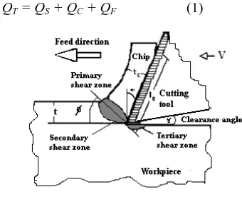
There are three main regions concerned with heating during the cutting process: the primary shear zone where the chip is formed and characterized by high shear deformation. The secondary and the tertiary zone where friction and shearing are combined are located respectively along the tool-chip interface and below the tool edge. In these regions heat is generated and flows into the workpiece, chip and cutting tool.
The energy required to deform the workpiece material and the chips is mainly converted into heat. As shown in Fig.1, there are three zones in which the heat is generated [2]:
Primary deformation zone; where plastic deformation takes place and QS is generated.
Secondary deformation zone; where the deformation takes place in the tool-chip interface and as the result of friction force, QC occurs.
Tertiary deformation zone; where the heat is generated due to friction between tool clearance face and newly generated workpiece surface, QF.
Thus, the total heat, QT can be obtained by the following
Eq. (1) [2].
QT = QS + QC + QF (1)
H. Yanda, J. A. Ghani, C. H. Che Haron
Copyright © 2007 Praise Worthy Prize S.r.l. - All rights reserved International Review of Mechanical Engineering, Vol. 5, N.2 Special Issue on Heat Transfer The machining problems of cast iron have been not
necessary foundry-related, but most of problem were due to the microstructure formation during the machining process itself. According to Jaharah et al [3], the width of microstructure changes, increases with the increase in wear land and feed rate. Therefore, study on the machinability of ductile cast iron is required to improve the productivity as well as to obtain the optimal machining parameters.
The temperatures, and also the effective stress generated on the cutting edge, are affected most by cutting speed, followed by feed rate and tool geometries [4]. Controlling the generated temperature is also important in maintaining and controlling the microstructure and hardness underneath workpiece’s surface [5]. In addition the worn tools caused overheating in the machined surface, resulting in changes to the microstructure of the work material.
The temperature is also an important parameter controlling to tool wear and consequently the tool life, the quality of the surface finish, chip segmentation and the choice of lubrication. Furthermore, thermal aspects become more important with high cutting speeds used presently in industrial processes.
A large number of techniques [6] have been developed to quantify the temperature, which can be classified as intrusive (e.g. thermocouple technique [9] or non-intrusive techniques (e.g. pyrometry technique [10]-[12]). Most of the above mentioned experiments are expensive, high risk and time consuming, therefore as an alternative, machining simulation is suggested. By performing the machining simulation, problems related to high cost, time, and injuries caused by high temperature and other high risks in machining experiments can be prevented.
This paper presents the application of FEM simulation to predict the effect of tool geometries (rake angle and clearance angle) on temperature generated on workpiece and chip formation.
II.
Literature Review
II.1. Temperature Measurement Techniques
The heat generated in cutting is one of the most important topics investigated in machining. There are several experiment techniques that have been developed by many researchers before for the measurement of temperature in various machining processes and manufacturing applications. Some of the techniques can be categorized as: (1) Calorimetric [13][14] (2) thermocouples [15], (2) infra-red photography [16][17]; (3) optical infrared radiation pyrometers [18], and others. All of experiment techniques required high cost and time.
The second highest heat generated was occurred on the tool-chip formation interface as shown in Fig.1. The ingenious method of determining the partition of heat generated in cutting between the tool, the workpiece, and the chip can be decided by previous researcher [19]. Fig. 2 shows a typical distribution of heat in the workpiece, the tool, and the chips with cutting speed [17].
II.2. Finite Element Analysis (FEA) Technique
Finite Element Analysis (FEA) technique was first introduced in 1960s and has been widely used in designing tools and forming processes. Based on the success of FEM simulations for bulk forming processes, many researchers developed their own FEM codes to analyze metal cutting processes during the early 1980s up to now [20]-[25].
A rigid sharp tool and elasto-plastic workpiece, and defined a node separation criterion based on the geometry of the element approaching the edge of cutting tool were assumed [21]. An early version of a commercial implicit FEM code Deform-2D™ was used [21]. This code uses four-node quadrilateral elements and is based on a static Lagrangian formulation. Scientific Forming Technologies Corporation [26] introduced Deform-3D™ code that has been commonly used by researchers and industry for machining simulation.
Applications of FEM models for machining can be divided into six groups: a) tool edge design, b) tool wear, c) tool coating, d) chip flow, e) burr formation and f) residual stress and surface integrity. The direct experimental approach to study machining processes is expensive and time consuming. For solving this problem, the finite element methods are most frequently used.
Modeling tool wear using FEM has advantages over conventional statistical approach because it requires less experimental effort and it provides useful information
H. Yanda, J. A. Ghani, C. H. Che Haron
Copyright © 2007 Praise Worthy Prize S.r.l. - All rights reserved International Review of Mechanical Engineering, Vol. 5, N.2 Special Issue on Heat Transfer such as deformations, stress, strain and temperature in
chip and the workpiece, as well as the cutting force, tool stress and temperature on the tool working under
The rate of heat generated due to friction is given by Eq. (3). velocity between tool and chip, and ζ is the mechanical equivalent of heat. The generated heat due to friction is given to each of the two contacting bodies, which are chip and tool in this case, by equal proportions.
The workpiece loses heat to the environment due to
where h is the convection heat transfer coefficient of the workpiece, Tw is the workpiece surface temperature, and
T0 is the ambient temperature.
III. Modeling and Simulation of Generated
Temperature
III.1. Machining Parameter
Twelve runs of simulation were conducted for various design of rake angles of 15, 20, and 30 deg, and clearance angles of 5, 7, 8, and 9 deg, while nose radius was kept constant at 0.4 mm. The machining parameter, such as cutting speed, feed rate and depth of cut, were
kept constant at 200 m/min, 0.35 mm/rev and 0.3 mm respectively as shown in Table I.
TABLE I
INPUT PARAMETERS IN THE SIMULATION PROCESS
III.2. Material Properties and Simulation Modeling
Fig.3 shows the geometry and schematic of orthogonal cutting condition model for the rake angle of 15 deg and clearance angle of 7 deg.
stress σ models Material constants
Variables
Oxley model
σ = σ1εn σ1, n = f(Tmod) ε, έ, T
Parameters
Cutting speed Kept constant at 200 m/min Feed rate Kept constant at 0.35 mm/rev Depth of cut Kept constant at 0.3 mm Nose radius (rέ) Kept constant at 0.4 mm Rake angle (α) 15, 20 and 30
Clearance angle (β) 5, 7, 8 and 9
H. Yanda, J. A. Ghani, C. H. Che Haron
Tool geometry of DNMA432 (WC as base material, uncoated tool)
Modulus of elasticity (GPa) 641
Poison ratio 0.25
Boundary condition Initial temperature (oC) Shear friction factor
Heat transfer coefficient at the workpiece-tool interface (N/s. mmoC)
20 0,6 45
Workpiece geometry (ductile cast iron FCD500 grade) Depth of cut
Workpiece properties (Ductile cast iron FCD500; Poisson’s ratio, 0.275)
Modulus elasticity (GPa) 169
Thermal conductivity (W/m. °C) 35.2 Thermal expansion Coefficient (·10-6 °C-1) 12.5
Heat capacity (N/mm2 ° C) 3.7
Emissivity 0.95
Others
The fraction of plastic work conversion into heat, қ
0.9
Mechanical equivalent of heat, ζ 1.0
Density (g/cm3) 7.875
Convection heat transfer coef. , N/(mm OC) 0.4
The work piece was ductile cast iron FCD500 grade and the cutting tool used was code number DNMA432 (tungsten, uncoated carbide tool, SCEA= 0; nose radius = 0.4mm, and nose radius angle 55o). This material was chosen as the workpiece material in this study because it was widely used in automotive component. Table II thermal properties and also boundary condition for simulation model are given in Table IV.
III.3. Design of Cutting Tool Geometries
Cutting tools were designed for various positive rake angles of 15, 20 and 30 deg and the clearance angles of 5, 7, 8 and 9 deg, while nose radius was kept constant at 0.4 mm. Geometries of tool carbide with code number DNMA432 can be seen in Fig.4.
Table V shows the variation of tool geometries where there are four clearance values for each rake angle. The twelve combinations of tool geometries were designed using Solid Work software as shown in Fig 5b, 5c, and 5d. The schematic diagram of cutting tool geometries is shown in Fig. 5a.
Workpiece geometry (ductile cast iron FCD500 grade) Depth of cut the workpiece at a constant speed and constant feed rate.
Fig. 5. (a) Schematic diagram of tool geometries; (b), (c), and (d) various designs of rake angles of 15, 20, and 30 deg, and clearance
angle and nose radius were kept constant at 7 deg and 0.4 mm Fig. 4. Geometries of tool carbide with code number DNMA432
H. Yanda, J. A. Ghani, C. H. Che Haron
Copyright © 2007 Praise Worthy Prize S.r.l. - All rights reserved International Review of Mechanical Engineering, Vol. 5, N.2 Special Issue on Heat Transfer A 3D finite element model was developed using
Deform-3D 6.1 finite element modeling software as shown in Fig. 6. The modeling approach is based on updated Lagrangian formulation for large plastic deformation analysis to simulate chip formation. The formation of chip from initial mesh (Fig. 6a) until it forms continuous chip at step 100, 200 and 500 (Fig. 6b, 6c and 6d respectively) were developed by 6170 number of elements and 1513 nodes for cutting tool, and 4746 number of elements and 1190 nodes for workpiece. The simulations were done in 500 step for transient condition and 500 steps for steady state condition (1000 steps in totally).
The workpiece and the tool are characterized by non uniform mesh distribution in the simulation. Very small element (20% of feed or 0.06 mm) is required in the contact area between tool and workpiece because of very large temperature gradient and stress that will be developed in this region during the simulation.
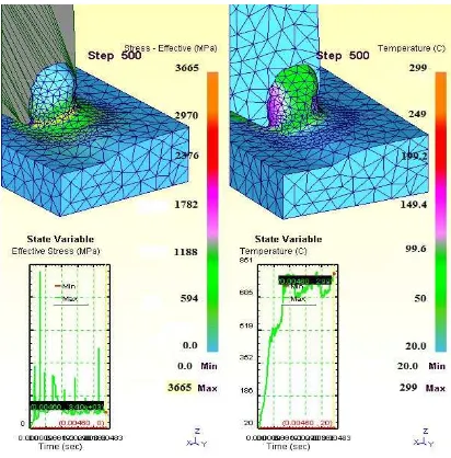
Fig.7 shows an example of transient simulation result for rake angle of 15 deg and clearance angle of 7 deg, the cutting speed of 100 m/min, feed rate of 0.35 mm/rev and DOC of 0.3 mm, at 500 steps of simulation running.
IV. Simulation Results and Discussion
Table VI shows the simulation results for all combination of various rake angles and clearance angles at cutting speed of 200 m/min, feed rate of 0.35 mm/rev and depth of cut (DOC) of 3 mm.
Table VI
THE RESULT OF SIMULATION FOR CUTTING FORCE,STRESS,STRAIN,AND TEMPERATURE
No Rake
angle,
Clearance angle,
Cutting
speed, V Feed rate, f DOC, a Temp, T
Cutting force, Fc
Stress, σ Strain, ε
[deg] [deg] [m/min] [mm/rev] [mm] [oC] [N] [MPa] [mm/mm]
1 15 5 200 0.35 3 321 346 4320 6.11
2 15 7 200 0.35 3 318 347 4230 6.56
3 15 8 200 0.35 3 334 400 4195 6.24
4 15 9 200 0.35 3 304 402 4340 7.13
5 20 5 200 0.35 3 299 239 3565 5.03
6 20 7 200 0.35 3 304 295 3690 4.96
7 20 8 200 0.35 3 272 271 3690 5.56
8 20 9 200 0.35 3 263 297 3720 5.65
9 30 5 200 0.35 3 198 165 3360 4.31
10 30 7 200 0.35 3 206 178 3540 4.45
11 30 8 200 0.35 3 218 196 3537 5.07
12 30 9 200 0.35 3 225 262 3400 4.68
Fig. 6. (a) Initial mesh and tool indentation, (b) Chip formation at step 100, (c) Chip formation at step 200, (d) Developed continues
chip at step 500
Fig. 7. Example of the transient simulation result for cutting speed of 200 m/min and rake angle of 15 deg and clearance
International Review of Mechanical Engineering (I.R.E.M.E), Vol. 5, N.2 Special Issue on Heat Transfer, February 2011
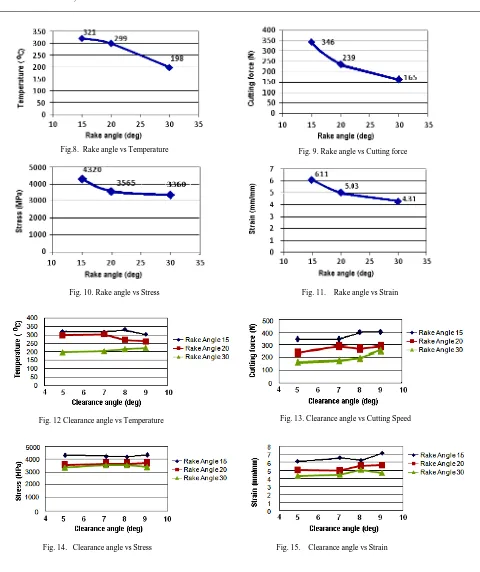
IV.1. The Effect of Rake Angle (α)
By increasing the rake angle, the temperature generated, cutting force, stress, and strain are decreasing as shown in Fig. 8, 9, 10 and 11 respectively. For example, increasing the rake angle from 15 deg to 30 deg (clearance angle of 7 deg), will reduce the temperature generated on workpiece from 321 oC to 198 oC, the cutting force from 346 N to 165 N, stress from 4320 MPa to 3360 MPa, strain from 6.11 to 3.41 mm/mm.
This is due to the reason that by reducing the temperature, consequently reducing the cutting force, stress, and strain. The cutting force, stress, strain decreased because of the small tool/chip contact area. When increasing the rake angle, the contact area at the interface between the tool and workpiece will decreases. This is agreeable with theory and experiment done by [28].
Fig.8. Rake angle vs Temperature Fig. 9. Rake angle vs Cutting force
Fig. 10. Rake angle vs Stress Fig. 11. Rake angle vs Strain
Fig. 12 Clearance angle vs Temperature Fig. 13. Clearance angle vs Cutting Speed
International Review of Mechanical Engineering (I.R.E.M.E), Vol. 5, N.2 Special Issue on Heat Transfer, February 2011
IV.2. The Effect of Clearance Angle (γ)
Increasing the clearance angle does not much influence the temperature generated, cutting force, stress, and strain as shown in Fig. 12, 13, 14, and 15 respectively. All of these results were also agreeable with the theory [29], because the change of clearance angle will not affect the cutting force and stress, therefore the temperature generated on workpiece will not be affected.
The increase of clearance angle will slightly affects the wear rate. Clearance angle will affects wear and tool life of the cutting tool because it will rubs against the freshly cut metal surface. In industry, the clearance angle is varied, but often in the order of 6 – 10 deg [30].
IV.3. Chip Formation: Generated Temperature on Primary and Secondary Deformation Zone.
Heat generation in metal cutting process is primarily due to shear deformation of the work material during chip formation. The temperatures of the tool body, however, are mainly increased due to the heated chip passing over the chip–tool interface.
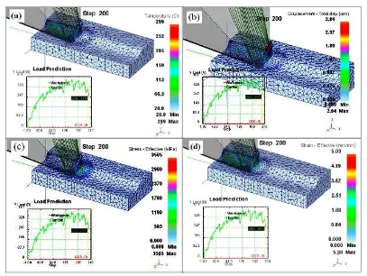
Fig. 16 shows the simulation results for temperature generated, displacement, stress, and strain for rake angle
of 20 deg and clearance angle of 5 deg (cutting speed of 200 m/min, feed rate of 0.35 mm/rev and DOC of 3 mm).
The highest temperature of about 299 oC was occurred at a sliding region on the primary shear zone as shown in Fig 16a.
The biggest displacement was achieved about 2.84 mm in total displacement at the end of chip formation (Fig. 16b). The biggest deformation was occurred on the primary deformation zone, followed by the secondary deformation zone. This also causes higher stress occurred in this area, about 3565 MPa in primary shear zone (Fig.16c). These results are agreeable with [31], where the major deformation during cutting process were concentrated in two region close to the cutting tool edge, and the bigger deformation were occurred in the primary deformation zone, followed by secondary deformation zone, sliding region and sticking region.
Fig. 16d shows the highest effective strain occurred on primary shear zone about 5.03 mm/mm, and then followed by secondary shear zone about less than 2.51 mm/mm.
H. Yanda, J. A. Ghani, C. H. Che Haron
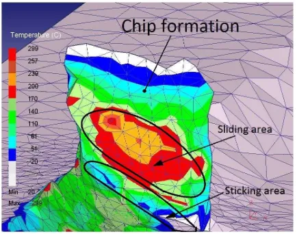
Copyright © 2007 Praise Worthy Prize S.r.l. - All rights reserved International Review of Mechanical Engineering, Vol. 5, N.2 Special Issue on Heat Transfer Fig. 17 shows the sticking area and sliding area at chip
formation. In the sticking region, the work piece material adheres to the tool and shear occurs within the chip, the high frictional force caused high temperature generated. Therefore, the highest temperature in the chip occurred in the sliding region (contour of yellow and red color that generated temperature obtained from simulations are agreeable with the results given in the literature.
From the simulation results, it can be concluded that by increasing the rake angle (α) in the turning of ductile cast iron using carbide tool, will improves the machining performance, since it will reduces the temperature generated, cutting force, stress, and strain. But, by
increasing the clearance angle (γ), it does not has much influence on the temperature generated, cutting force, stress and strain.
For chip formation, in the sticking region, the work piece material adheres to the tool and shear occurs within the chip, the frictional force is high and consequently temperature is generated. Therefore, the highest temperature in the chip usually occurs in the sliding region.
The temperature is an important parameter that controlling the quality of the surface finish, tool wear, and chip segmentation. Controlling the temperature generated is also important in maintaining and controlling the microstructure and hardness at underneath workpiece’s surface.
Furthermore, thermal aspects become more important topic with high cutting speeds presently used in industrial processes. Therefore simulation techniques is
recommended to study and evaluate the thermal aspects in metal cutting process.
Acknowledgments
The authors would like to thanks to the Government of Malaysia and National University of Malaysia for their financial support under 03-01-01-SF1214 and UKM-GUP-BTT-07-25-025 Grants.
References
[1] Barrow, G., A review of experimental and theoretical techniques for assessing cutting temperature, Annals of the CIRP, Vol. 22, n. 2, pp.203–211, 1973.
[2] Seker, U., Korku, I., Turkut, Y., Boy, M. The
measurement of temperature during machining,
International Conference Power Transmission, Ankara, Turkey, 2003.
[3] Jaharah, A.G., Che Hassan, C. H., Muhamad, N. Machined surface of AISI H13 tools steels when end milling using P10 tin coated carbide tools, European J. of Scientific Research, Volume 26, n..2, pp.247-254. 2009. [4] Jaharah, A. G., Wahid, S. W., Che Hassan, C. H., Nuawi,
M. Z., Mohd Nizam, A. R.,. The effect of uncoated carbide tool geometries in turning AISI 1045 using Finite Element Analysis. European Journal of Science Research, Vol.28, n.2, pp.271-277, 2009b.
[5] Jaharah, A. G., Choudhury, I.A., Masjuki, H.H., Che Hassan, C. H.. Surface Integrity of AISI H13 Steel in the End Milling Process, Int. J. of Mechanical and Materials Engineering (IJMME). Vol.4, n.1, pp.88-92, 2009. [6] Komanduri, R. and Hou, Z.B., A review of the
experimental techniques for the measurement of heat and temperature generated in some manufacturing processes and tribology, Tribology International, Vol. 34, pp.653– 682, 2001.
[7] El-Wardany, T.I., Mohamed E. and Elbestawi, M.A. Cutting temperature of ceramic tools in high speed machining of difficult-to-cut materials, Int.. J. of Machine Tools and Manufacture, Vol. 36, pp.611–634, 1996. [8] O’Sullivan, D. and Cotterell, M. Temperature measurement
in single turning point, Journal of Materials Processing and Technology, Vol. 118, pp.301–308, 2001.
[9] Muller, B. and Renz, U. Time resolved temperature measurements in manufacturing, Measurement, Vol. 34, pp.363–370, 2000.
[10] Outeiro, J.C., Dias, A.M. and Lebrun, J.L. Experimental assessment of temperature distribution in three-dimensional cutting process’, Journal of Machining Science and technology, Vol. 8, n. 3, pp.357–376, 2004.
[11] Ranc, N., Pina, V. and Herve, P. Optical measurements of phase transition and temperature in adiabatic shear bands in titanium alloys’, J. of Physique IV France, Vol. 10, pp.347–352, 2000.
[12] Sutter, G., Faure, L., Molinari, A., Ranc, N. and Pina, V. An experimental technique for the measurement of temperature fields for the orthogonal cutting in high speed,
International Journal of Machines Tools and
Manufacture, Vol. 43, pp.671–678, 2003.
[13] Thompson. B. Count Rumford, an enquiry concerning the source of heat which is excited by friction. (London: Phil Trans Royal Soc, 18th edition, 1798, pp 278–287).
[14] Joule JP. On the mechanical equivalent of heat. (London: Phil Trans of the Royal Soc,70th edition, 1850, pp.61–81) [15] Rall DL, Giedt WH. Heat transfer and temperature
distribution in metal cutting tool. (Trans ASME, 78th
edition, 1956, pp.1507–15). Fig. 17. Sticking and sliding areas in secondary
H. Yanda, J. A. Ghani, C. H. Che Haron
Copyright © 2007 Praise Worthy Prize S.r.l. - All rights reserved International Review of Mechanical Engineering, Vol. 5, N.2 Special Issue on Heat Transfer [16] Boothroyd G. Photographic techniques for the determination of
metal cutting temperatures. Journal of Applied Physics, Vol. 12, pp.238–242, 1961.
[17] Boothroyd G. Temperatures in orthogonal metal cutting, Proceeding Int. Mech Engineering, London, 1963, pp.789–810. [18] Schwerd F. Determination of the Temperature Distribution
During Cutting (Z VDI, 9th Edition, pp.211, 1933).
[19] Komanduri, R., Hou. Z.B., A review of the experimental techniques for the measurement of heat and temperatures generated in some manufacturing processes and tribology, Tribology International, Vol. 34, pp. 653–682, 2001.
[20] Marusich, T.D., Ortiz, Modeling and Simulation of High-Speed Machining, International Journal for Numerical Methods in Engineering, Vol. 38, n.21, pp.3675–3694, 1995.
[21] Cerenitti A. E., Fallbohmer B. P., Wu C.W.T. & Altan B.T., Application of 2D FEM to Chip Formation in Orthogonal Cutting, J. of materials Processing Tech., Vol.59, pp.169 - 180, 1996. [22] Cerenitti. A. E., Lazzaroni.C., Menegardo. L. & Altan. T., Turning
Simulation Using a Three-Dimensional FEM Code, Journal of materials Processing Technology, Vol.98, pp. 99 - 103, 2000. [23] Xie, J. Q., Bayoumi, A.E., & Zbib, H. M., FEA Modelling and
Simulation of Shear Localized Chip Formation in Metal Cutting, J. of Materials Processing Tech., Vol.38, pp.1067-1087, 1998. [24] Shet, C., Finite Element Analysis of the Orthogonal Metal Cutting
Process, Journal of Materials Processing Technology, Vol.105, pp.95-109, 2000.
[25] Jawahir, I. S., An Intermediatary Level Short Course on Machining Process Modelling and Optimization for Improved Productivity (Machining Research Laboratory Center for Manufacturing, Department of Mechanical Engineering Lexington, USA, 2008).
[26] Columbus, O.H. , DeformTM - 3D Machining (Turning) Lab
(Scientific Forming Technologies Corporation, 2007).
[27] Mackerle, J., Finite Element Analysis and Simulation of Machining: a Bibliography (1976 – 1996), Journal of Materials Processing Technology, Vol.86, 17-44, 1999.
[28] Gunay, M.G., Korkut, I., Aslan, E., and Eker, U.S. Experimental investigation of the effect of cutting tool rake angle on main cutting force, Jour. of Materials Processing Technology Vol. 166 (2005), p. 44–49.
[29] Stephenson. A.A, Agapiou, J.S, Metal Cutting Theory and Practice, Marcel Dekker. Inc, New York, 1996
[30] Trent, E. M., Metal Cutting (London: Butterworth - Heinmann Ltd, 1991.
[31] V. Kalhori, in: Modelling and Simulation of Mechanical Cutting, Doctoral Thesis, Institutionen for Maskinteknik, Sweden (2001).
Authors’ information
[email protected], [email protected], [email protected]
1
Hendri Yanda was born at Bukit Tinggi, West Sumatera, Indonesia on August 19th, 1970. He
graduated his bachelor in 1996 at the Department of Mechanical Engineering, Andalas University, Padang, West Sumatera, Indonesia. After graduation from Andalas University, He was accepted directly as lecturer and researcher at Mechanical Engineering Department, Engineering Faculty, Andalas University, Padang, West Sumatera, Indonesia. He obtained MSc degree in Advanced Engineering/Manufacturing from Engineering Manufacturing, School of Engineering, Engineering Faculty, Sheffield Hallam University, Sheffield,United Kingdom. 2001. Currently, he is a research assistant and PhD student at the Department of Mechanical and Material Engineering, Faculty of Engineering and Built Environment, National University of Malaysia.
His interest research subject areas are Engineering Science, Manufacturing and Production Engineering, and Cutting Tool Technology. His areas of expertise are in Engineering Science, Manufacturing and Production Engineering, Machining and Metal Cutting Simulation and Advanced Engineering.
Some of the publications related to FEM in machining are: Application of FEM in Investigating Machining Performance, 2009-2010, accepted to publish on Advanced Material Research (AMR), International; Effect of Rake Angle on Stress, Strain and Temperature on the Edge of Carbide Cutting Tool in Orthogonal Cutting Using FEM Simulation, ITB Journal of Engineering Science, Vol. 42 (2), pp. 179-194, 2010, International; Optimization of Material Removal Rate, Surface Roughness and Tool Life on Conventional Dry Turning of FCD 700, Project Leader, 2010, accepted to publish on International Journal Mechanical and Materials Engineering. International; Simulation of Turning Process of AISI 1045 and Carbide Tool Using Finite Element Method, co-leader, Proceeding of the 7th WSEAS Int. Conf. on CIMMACS '08 (Computational Intelligence, Man-Machine Systems and Cybernetics), Cairo, Mesir, December 2008; Effect of Rake Angle and Clearance Angle on the Wear of Carbide Cutting, Project Leader, Engineering e-Transaction (ISSN 1823-6379) Vol. 4, No. 1, June 2009, pp 7-13.
2 Jaharah A. Ghani currently is a
lecturer and researcher at the Department of Mechanical and Material Engineering, Faculty of Engineering and Built Environment, National University of Malaysia. She graduated in BEng University of Malaya, Malaysia. Her current research interests are machining technology of tool steels, cast iron and aerospace materials.
3Che Hassan Che Haron graduated from
H. Yanda, J. A. Ghani, C. H. Che Haron
H. Yanda, J. A. Ghani, C. H. Che Haron
![Fig. 2. Typical distribution of heat in the workpiece, the tool, and the chips with cutting speed [17]](https://thumb-ap.123doks.com/thumbv2/123dok/855090.471528/2.595.314.538.192.344/fig-typical-distribution-heat-workpiece-chips-cutting-speed.webp)
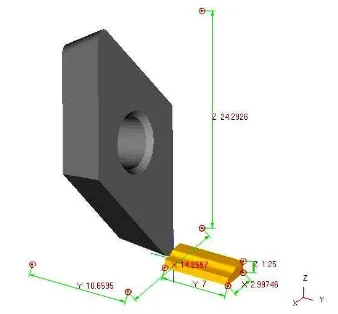
![Fig. 4. Geometries of tool carbide with code number DNMA432 [26]](https://thumb-ap.123doks.com/thumbv2/123dok/855090.471528/4.595.309.521.78.194/fig-geometries-tool-carbide-code-number-dnma.webp)