INHERITING TEXTURE MAPS BETWEEN DIFFERENT COMPLEXITY 3D MESHES
A. Symeonidis a, A. Koutsoudis b, G. Ioannakis a, C. Chamzas a,*
a
Dept. of Electrical and Computer Engineering, Democritus University of Thrace b“ATHENA” Research
and Innovation Centre, ILSP, Xanthi Branch (former CETI)
Commission V, WG V/2
KEY WORDS: Texture transfer, inverse texture map projection, texture registration
ABSTRACT:
3D digitisation has been applied in different application domains. Due to the continuous growing interest, commercial and experimental 3D acquisition systems have evolved. Nevertheless, there isn’t an all-in-one solution, thus there is a need for combining different technologies in order to exploit the advantages of each approach. In this paper, we present a solution to a specific problem related to the combination of 3D data resulted from a non-colour laser triangulation scanner and a shape-from-silhouette system. Our approach combines the data of these two 3D acquisition systems in order to produce a hybrid 3D mesh model with the geometric accuracy and detail captured by the laser scanner and the high resolution textural information of the shape-from-silhouette system. We propose an algorithm that is based on virtual photo shooting and an inverse texture map projection phase. We present an example of our algorithm’s operation on exchanging the texture maps of a replica artefact which has been digitised by both systems.
* Corresponding authors: E-mail addresses, A. Symeonidis - [email protected] and C. Chamzas - [email protected] 1. INTRODUCTION
3D scanning technologies have been applied in different application domains with great success. They have the potential to improve the efficiency and cost-effectiveness in areas such as planning, design, construction, inverse engineering or even project maintenance. Several approaches have been proposed for the 3D digitisation of real world objects. Colombo et al. (2006) mention that 3D scanning applications can range from engineering and architecture, to archival and preservation of cultural heritage, and entertainment. Over the last decade several industries, research institutes, museums, etc. have invested on such systems. Even in the fragile cultural heritage domain many 3D digitisation projects have been crowned with success. Although, the market of 3D scanning systems is still evolving, those that have invested in early systems are already referring to them as obsolete due to the advances introduced by the research and the development of new low cost acquisition systems. Computer vision researches have produced an arsenal of algorithms that can be used for the production of low cost 3D scanning systems from images (PhotoModeler, 2013; PhotoScan, 2013). Even if their performance in some cases is comparable to laser scanners (Koutsoudis et al., 2014), in general laser scanning outperforms 3D models generated from photo-based 3D scanning. Still, it is a fact that the cost-performance ratio is an important factor when selecting a 3D scanning system.
In this paper, we present an algorithm that combines two different-in-principle 3D scanning systems in order to produce 3D meshes that reflect only the advantages of each approach. This combination can also be considered as an attempt to expand both systems’ life-cycle by introducing a method of data merging. Data derived from a non-colour high accuracy 3D laser triangulation system (Kreon 3D KLS171 on a Faro Silver arm) and a shape-from-silhouette software based solution (3D
SOM ) are utilised in order to produce a 3D mesh model which reflects the geometrical accuracy provided by a laser scanner and the texture map quality captured by modern digital cameras. The scope of the proposed algorithm is not to produce a 3D mesh model for archiving purposes but to visually enhance the models resulted by the non-coloured 3D laser scanner. The algorithm is based on a virtual photoshooting session of the shape-from-silhouette model in order to extract the texture information into a set of images. Then, those images are inverse-projected back on the initially texture-less 3D mesh derived from the laser scanner. The virtual images are merged together in order to produce the final texture map of the high detail 3D mesh model.
The paper is organised as follows. Section 2 provides an overview of the related work. In section 3, we describe the acquisition systems and in section 4 we give a detailed analysis of our algorithm. In section 5 experimental results depict the performance of the proposed solution. Finally, we conclude with remarks regarding the evolution of our approach.
2. RELATED WORK
The approach of capturing surface texture information from real world objects using different viewpoints has been utilised by many researchers. Szeliski (1997) extracted 3D geometry and photometric data of real world objects using multiple images. Soucy et al. (1996) developed sensors and 3D reconstruction algorithms for the creation of coloured 3-D triangular meshes using a set of range images with registered colour measurements. Lensch et al. (2000) presented a system which automatically registers and stitches texture maps acquired from multiple images onto the surface of a 3D model. Rocchini et al. (1999) proposed an approach for mapping and blending textures on 3D meshes. Niem and Broszio (1995) presented an algorithm for 3D mesh texture mapping using images acquired from ISPRS Annals of the Photogrammetry, Remote Sensing and Spatial Information Sciences, Volume II-5, 2014
multiple camera viewpoints. Neugebauer and Klein (1999) presented a technique to enhance the existing geometry of real world 3D replicas by using textures reconstructed from a sparse set of unregistered still photographs. Bernardini et al. (2001) presented methods to construct accurate 3D models of real world objects by integrating high-quality texture and normal maps with geometric data. In this work, we adapt the idea of photo shooting the shape-from-silhouette scanned 3D model from multiple viewpoints in order to extract the texture information from its surface.
3. 3D SCANNING SYSTEMS
One of the dominant 3D scanning techniques is laser triangulation. Some systems allow the manual sweeping of the laser beam over the object. This is a great advantage as it allows the complete digitisation of geometrically complex objects. The two digitisation systems that were used in this work were the Kreon KLS171 (Kreon, 2013) laser head on a mechanical Faro Silver arm (Faro, 2013) and 3D SOM Pro (3D–S.O.M., 2013; Baumberg et al., 2005), a shape from silhouette software based approach.
More specifically, the Kreon KLS171 non-colour 3D laser scanning system is a combination of a laser head and a mechanical Faro Silver arm. The measurement resolution of the laser head towards the sensor is 25μm and the laser line resolution (distance between two consecutive points) is 120 μm. The scanning head is equipped with two cameras located at a 450 angle. Thus, data capturing is not interrupted even in cases where one of the two cameras is occluded. The object that has been used for the evaluation of the proposed algorithm was captured with this system in a five hour period.
On the other hand, the 3D SOM Pro is software based 3D reconstruction approach that is based on the shape-from-silhouette principle. The software automatically extracts the silhouette of an object from a set of images and reconstructs an approximation to the original object as concave areas that are not visible on the silhouette’s contours are not modelled. In order for the software to identify the position of the object in the real world, a special pattern is been placed under the object. The textural information that is captured depicts the lighting conditions during the photo shooting phase. An automated procedure performs colour equalisation and blending between the areas where different images are used in combination to produce the final texture map. The performance evaluation object that has been used was captured in less than an hour.
4. INHERITING TEXTURE MAP DATA
Texture map inheritance is based on the idea of virtual photo shooting the 3D mesh produced by the shape-from-silhouette technique using different viewpoints. This Low Complexity Model (LCM) carries the texture information that we are going to extract into a set of images. Then, those images are inverse-projected back on the textureless High Complexity Model (HCM) which was produced by laser scanning.
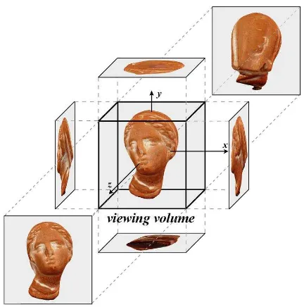
We assume that the two models are already aligned and centred at the origin of a right handed Cartesian coordinate system. As mesh alignment is out of the scope of the current work, we used Geomagic Studio 10 (Geomagic, 2013) to align the two meshes. We consider the sides of a bounding cube as the projection planes on which the textured surface of LCM is orthogonally projected on (Figure 1). Those six projected images are merged
into a single bitmap in order to produce the new HCM texture map.
Figure 1. The virtual photo shooting stage in our first approach
Once virtual photo shooting is completed, the back-projection stage is initiated. The centre of mass for all triangles in both LCM and HCM are computed. Then for each HCM triangle, we detect the LCM triangle with the minimum Euclidean distance. The distances are computed between the centres of mass. After that, we identify the image in which the nearest LCM triangle is best captured (closest to parallel projection). This is done by calculating the dot products between the LCM triangle’s normal vector and the normal vectors of the sides of the bounding cube. The UV map coordinates of the HCM triangle depend on its orientation and position within the HCM mesh. The same procedure is repeated for all HCM triangles.
The first approach is characterised by its low computational complexity but it produces incomplete texture maps with objects that carry occluded surface areas due the positioning of the camera on the facets of the bounding cube. The second proposed approach is also based on a virtual photo shooting session of the LCM. The viewpoints selection is now based on a more complex selection scheme which takes under consideration the surface morphology of both LCM and HCM. A viewpoint is computed for each one of the HCM triangles. Thus, if HCM consists of N2 triangles then N2 images of the
surface of the LCM will be captured. An HCM triangle will be textured using portions of an image.
More specifically, we consider as t1i (i=0,1,2, … , N1-1) the
described by the nearest three t1k triangles are calculated. Then,
the distances dpjk between the centre of mass of the t2j triangle
and the planes derived by the three t1ktriangles are calculated.
The nearest t1k triangle to t2j is the one with the smallest dpjk
distance. The texture map of the neighbourhood of the selected ISPRS Annals of the Photogrammetry, Remote Sensing and Spatial Information Sciences, Volume II-5, 2014
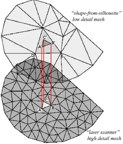
t1k triangle will be inherited to t2j. As shown in Figure 2, the digitisation methodologies being used. Thus, the projected vertices (A', B' and C') might lie outside of the boundaries defined by the vertices (D, E and F) of the nearest t1k triangle
(Figure 3). This is not an issue, as we are also interested in the texture information carried by the neighbourhood around the LCM triangle and not the exact area defined by its boundaries.
Figure 2. The vertices A, B, C of the HCM triangle are projected to the plane specified by the vertices D, E, F of the
nearest LCM triangle, where A’, B’, C’ are their projections
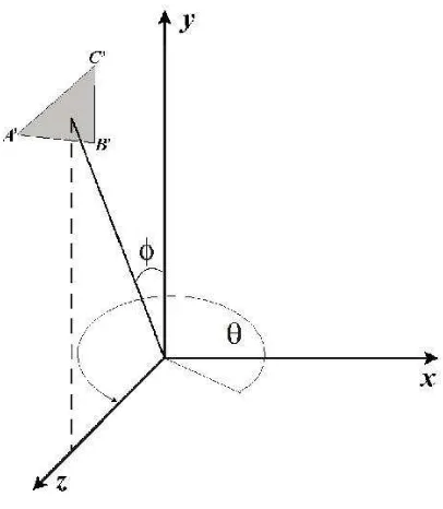
Once the nearest LCM triangle is detected, a set of affine transforms are applied to LCM in order to position the nearest triangle in front of the virtual camera which is positioned on the positive side of the Z axis pointing towards the origin. Initially, a rotation around the Y axis is performed by an angle θ (Figure plane specified by the nearest LCM triangle (D, E, F) lie
outside of its boundaries
Figure 4. Initial position of LCM
After the application of the previously described affine transforms the plane defined by vertices A’, B’ and C’ is set parallel to the x0y plane and its normal (xn, yn, zn) is parallel to
the Z axis (Figure 6).
Figure 5. LCM rotated around the Y axis by an angle of θ.
The longest edge of the triangle defined by A’, B’ and C’ is then detected and an appropriate rotation around the Z axis by an angle ω is applied in order for the edge to be set parallel to the X axis. The angle ω is given by:
x x
x if A C
C A
A
'
'
,
'
'
'
cos
1
(4)
else
'
'
'
cos
2
1C
A
A
x
(5)
where A'x and C'x are the X coordinates of A' and C' vertices.
Figure 6. LCM rotated by an angle φ around Χ axis.
A translation is also applied so that one of the edge vertices coincides with the origin (Figure 7). This is the left vertex as we look the triangle from the positive side of the Z axis.
The texture of the rectangular that encloses the triangle A’B’C’ is captured. In most cases (as you see in Figure 7) we capture an area that contains this rectangular and the “security” margins tm (top margin), bm (bottom margin) and sm (side margins) around it in order to avoid distortion caused by blending and dithering techniques of the 3D imaging applications.
The location of the virtual camera is shifted on the Z axis and the capture distance varies proportional to the above mentioned distance dpjk between the centre of mass of the HCM triangle and the plane of the nearest LCM triangle. This contrivance guarantees that the camera is placed close to the LCM surface in relation with its dimensions and eliminates the possibility of another LCM facet to be in between. The texture contained in the captured area is projected to the camera viewpoint orthogonally and is unaffected.
Figure 7. The LCM surface that corresponds to a HCM triangle is captured into a single image
The dimensions height h and width w, in pixels, of the captured rectangular and the size of the margins are adjustable at the beginning of the procedure but it is constant for all t2j triangles
of the HCM. The optimum values depend on the number of the triangles of the HCM and the quality we want to give to the final model.
The relative position on the X axis of the “top” vertex (vertex B in Figure 7) and the last rotation of the triangle around the Z axis are also been kept.
The same procedure is followed for all t2j triangles. All captured
image portions are placed sequential in an array of r rows and c columns (where r x c ≈ N2: the total number of the HCM
triangles) and finally combined into a single bitmap (Figure 8). The first image portion which corresponds to the t20 triangle is
been placed at the bottom left corner of the array.
The calculation of the UV coordinates consummates the composition of the UV map. The three vertices of each triangle of the HCM are been classified as “bottom-left”, “bottom -right” and “top” (vertices P, Q and R as you see in the Figure ISPRS Annals of the Photogrammetry, Remote Sensing and Spatial Information Sciences, Volume II-5, 2014
9) depend on their relative location on the corresponding triangle at the moment of the texture capturing by the virtual camera.
Figure 8. The new texture map constituted by the captured image portions
The UV values result in connection with the “class” of the vertex (bottom-left, bottom-right or top), the number of rows r and columns c of the texture map, the location of the corresponding image portion in the texture map array, the relative position of the top vertex and the size of the security margins. The last rotation of the triangle around the Z axis is also considered.
Figure 9. The texture portions specified by the UV coordinates on a segment of the texture map
More specifically we consider as tmr and bmr the quotients of security margins tm and bm to the picture height h and smr the quotient sm to the picture width w. We also consider as pj the relative position of the top vertex of the t2j triangle on the X axis in the interval [0,1].
Figure 10. The LCM and HCM models. The HCM model carries the texture map inherited by LCM using the 2nd
approach
For all the t2j (j=0, 1, 2, … , N2-1) triangles of the HCM:
If the vertex is a bottom-left one:
U = [(j mod c) + smr] / c
(6)
V = [(j div c) + bmr] / r
(7)
Else if the vertex is a bottom-right one:
U = [(j mod c) + 1 – smr] / c
(8)
V = [(j div c) + bmr] / r
(9)
Else if the vertex is a top one:
U = [(1 – 2 * smr) * pj + (j mod c) + smr] / c
(10)
V = [(j div c) + 1 – tmr] / r
(11)
5. EXPERIMENTAL RESULTS
Figure 10 depicts the HCM after inheriting the texture map from the LCM.
In order to evaluate the performance of our approach, we selected an object which carries hollow areas on its surface which cannot be captured by the shape-from-silhouette technique. As mentioned before the bust was digitised using the two techniques. The LCM model is composed by 16.960 triangles (8.482 vertices) while the HCM model consists of 203.730 triangles (101.857 vertices).
The algorithm was executed on a PC with an Intel Core i7 processor, 4GB of RAM and a GeForece GTS 250 graphics card. The virtual photo shooting session and the inverse texture map projection was performed in 45 minutes.
Figure 11 depicts details of the texture inherited on the HCM mesh.
6. CONCLUSION
The cost of commercial 3D scanning systems and the need to extend the life cycle of such products leads to the development of algorithms that allow the combination of data derived by different systems. To this end, we presented an algorithm that allows the automated inheritance of texture information between a low quality textured mesh and a high quality textureless mesh. We applied the algorithm by scanning a replica bust using laser triangulation and shape-from-silhouette approaches. The results indicate that the data produced by the two systems can be combined in order to produce a 3D mesh which carries high geometrical and textural details. At the moment, we are working on texture map size optimisation by organising the different images on a more optimised approach.
Figure 11. Detail of the produced textured high resolution model
Acknowledgment:
This research has been co-financed by the European Union (European Social Fund - ESF) and Greek national funds through the Operational Program "Education and Lifelong Learning" of the National Strategic Reference Framework (NSRF) - Research Funding Program: THALES (MIS 379516) Investing in knowledge society through the European Social Fund.
REFERENCES
3D–S.O.M., 2013. 3D Software Object Modeller Pro, Web site: http://www.3dsom.com (Date of Access: May 10, 2014).
Baumberg, A., Lyons, A. and Taylor, R., 2005. 3D SOM-A commercial software solution to 3D scanning. Graphical models, 67(6), pp. 476-495.
Bernardini, F., Martin, I. M. and Rushmeier, H., 2001. High-quality texture reconstruction from multiple scans. In: IEEE Transactions on Visualization and Computer Graphics, Vol 7, No 4, pp. 318-332.
Colombo, C., Comanducci, D. and Del Bimbo, A., 2006. Low-Cost 3D Scanning by Exploiting Virtual Image Symmetries. Journal of Multimedia, 1(7), pp. 71-76.
Faro, 2013. Faro portable measurement solutions, FARO Technologies UK Ltd, Web site: http://www.faro.com (Date of Access: May 10, 2014).
Geomagic, 2013. Geomagic Studio, Geomagic Solutions, Web site: http://geomagic.com/en/products/studio (Date of Access: May 10, 2014).
Koutsoudis, A., Vidmar, B., Ioannakis, G., Arnaoutoglou, F., Pavlidis, G. and Chamzas, C., 2014. Multi-image 3D reconstruction data evaluation. Journal of Cultural Heritage, 15(1), pp. 73-79.
Kreon, 2013. Kreon 3D Scanning Solutions, KREON Technologies, Web site: http://www.kreon3d.com (Date of Access: May 8, 2014).
Lensch, H., Heidrich, W. and Seidel, H. P., 2000. Automated texture registration and stitching for real world models. In: The Eighth Pacific Conference on Computer Graphics and Applications, Hong Kong, China, Proceedings pp. 317-337.
Neugebauer, P. J. and Klein, K., 1999. Texturing 3d models of real world objects from multiple unregistered photographic views. In: Computer Graphics Forum, Vol. 18, No. 3, pp. 245-256.
Niem, W. and Broszio, H., 1995. Mapping texture from multiple camera views onto 3D-object models for computer animation. In: Proceedings of the International Workshop on Stereoscopic and Three Dimensional Imaging, pp. 99-105.
PhotoModeler, 2013. PhotoModeler Scanner, Eos Systems Inc., http://www.photomodeler.com/products/scanner/default.html (Date of Access: November 4, 2013).
PhotoScan, 2013. Agisoft PhotoScan, AgiSoft LLC, Web site: http://www.agisoft.ru (Date of Access: May 10, 2014).
Rocchini, C., Cignoni, P., Montani, C. and Scopigno, R., 1999. Multiple textures stitching and blending on 3D objects. In: ISPRS Annals of the Photogrammetry, Remote Sensing and Spatial Information Sciences, Volume II-5, 2014
Proceedings of the 10th Eurographics conference on Rendering, pp. 119-130.
Soucy, M., Godin, G., Baribeau, R., Blais, F. and Rioux, M., 1996. Sensors and algorithms for the construction of digital 3-D colour models of real objects. In: Proceedings, International Conference on Image Processing, Vol. 1, pp. 409-412.
Szeliski, R., 1997. From images to models (and beyond): a personal retrospective. In: Vision Interface, Vol. 97, pp. 126-137.