CALIBRATING THE NEW ULTRACAM OSPREY OBLIQUE AERIAL SENSOR
We present methods and results to calibrate the new oblique sensor UltraCam Osprey which was presented for the first time at the ASPRS 2013 conference and exhibition in Baltimore, MD, March 2013. Even if this was not the first time when oblique sensors were introduced into the market, the UltraCam Osprey did show several new conceptual details which are illustrated in this presentation. The design of the camera is focusing on two important characteristics, a metric nadir component which has been derived from the UltraCam Lp sensor, and collection efficiency through very large swath width. The nadir sensor consists of the 90 megapixel panchromatic camera, true-color RGB, and a near-infrared camera. Adding six oblique camera heads, with two each in forward and backwards direction, results in unmatched oblique collection efficiency. We first explain the camera and cone configuration along with the geometric layout of the sensor system. Then we describe the laboratory setup for geometric calibration of the UltraCam Osprey and the calibration process along with the actual results of one such calibration showing sub-pixel accurate image geometry. This proves that the UltraCam Osprey is a fully calibrated metric camera system suitable for photogrammetric survey applications.
INTRODUCTION
The UltraCam Osprey is the new oblique digital aerial camera by Microsoft and was presented for the first time at the ASPRS 2013 conference and exhibition in Baltimore, MD, March 2013. The camera is based on a concept which offer several new and unique advantages with a clear emphasis on professional photogrammetry and collection productivity. Most important is the metric nadir component which is based on the same design as the well-known UltraCam Lp camera (cf. Wiechert, Gruber, 2009). This nadir camera constitutes the ‘‘geometry backbone’’ of the UltraCam Osprey and enables traditional photogrammetric processing from an oblique aerial camera system. Osprey images are compatible with the UltraMap software supporting the full workflow from aero-triangulation to dense surface modelling and ortho-image creation. It is worthwhile to say that the six oblique camera heads making the pixel harvest extremely productive. The oblique cameras are aligned to the four cardinal direction at 45° off-nadir. Forwards and backwards are equipped with da double camera head, single cones look left and right.
THE ULTRACAM OSPREY DESIGN
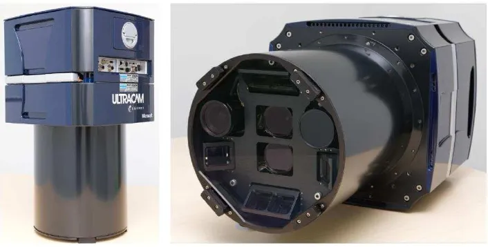
The camera consists of 10 camera heads. Four cones constitute the classical nadir camera for creating one 90 Mpixel panchromatic image at a focal length of 51 mm, as well as one true-color RGB at 25.5 mm focal length and one near-infrared image (cf. Figure 1 and Table 1). The remaining six camera cones are equipped with 80 mm lenses and high-quality optical prisms. The forward and backward looking cones are assembled pairwise, greatly enlarging the cross-track FOV of these twin cones. Table 1 describes the principal parameters of the camera system and the UltraCam Osprey design.
Newly developed proprietary lenses
New proprietary camera electronic for even faster frame rate
Even further improved image dynamic due to the new sensor electronics Integrated computers
Integrated solid state storage
Integrated UltraNav (GPS/INS/FMS system) Reduced size, weight, and power consumption Multiple camera configurations
Exchangeable lens systems (UltraCam Eagle only) by the introduction of a new precision mount system for the camera lenses
Figure 1: UltraCam Osprey (left) and cone layout (right)
Focal Length
Nadir PAN 51.0 mm Oblique Sensor Heads 80.0 mm
Nadir RGB and NIR 25.5 mm
Frame Format / Pixel Size
Nadir PAN 11674 * 7514 6.0 µm Oblique Sensor Heads 6870 * 4520 5.2 µm Nadir RGB and NIR 6735 * 4335 5.2 µm
FOV/ deg cross track along track
Nadir PAN (RGB) +/- 34.48 ° +/- 23.85 °
Nadir RGB (PAN) and NIR +/- 34.48 ° +/- 23.85 °
FOV/ deg
Oblique Fwd/Bwd - +/- (53,36° / 36,64°)
Oblique Left/Right +/- (57,59° / 32,41°) -
Table 1: Principal design parameters of the UltraCam Osprey
cross-track dimension of the oblique images are well tuned to each other. At a flying altitude of 1275 m and a nadir GSD of 15 cm the nadir looking image covers the area of 1750 m by 1127 m. The corresponding left and right oblique images overlap with the nadir image, yielding a combined and seamless image footprint of 115° FOV. The cross-track footprint size of the forward and backward oblique images is more than 1135 m. This supports a flight pattern where the flight line distance is 60% of the nadir footprint (40% side overlap). At a speed over ground of 60 m/sec the UltraCam Osprey frame rate of about 0,45 images /second (2,2 seconds TBFR) allows achieving a forward nadir overlap of 80% at a minimum GSD of 8,5 cm and less than 5 cm GSD with 60% endlap.
Figure 2: UltraCam Osprey footprint (left) and FOV diagram (right)
GEOMETRIC CALIBRATION
Geometric quality and the availability of calibration data is one of the mayor advantages of UltraCam Osprey. Thus it was part of the development process to expand the existing calibration laboratory. This laboratory is in use for the calibration of all cameras of the UltraCam Sensor Family. In order to allow for the larger field of view of the sensor we expanded the calibration target. Additional control points are available to cover the oblique cameras to the left and to the right. Tilting the camera by 90° enables to calibrate the forward and backward sensors as well.
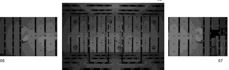
Figure 3: Camera calibration of the UltraCam Osprey. The extended calibration laboratory in Graz, Austria and its 3D Structure is the basis for calibration all camera heads of the UltraCam Osprey (left and right oblique and nadir).
is well proven and consists of 84 shot positions (cf. Ladstaedter et al, 2010). This is the basis for the calibration of the oblique camera heads. The exterior orientation parameters of the nadir cones are introduced into the setup for the oblique cameras. This does improve the redundancy of the adjustment together with eccentricity parameters.
The calibration procedure for the oblique cameras is based on 252 images taken from three camera stations at different rotation angles. Thus a highly redundant set of image positions can be automatically measured and introduced into the least squares bundle adjustment procedure. The entire set of measured image positions is approximately 20000 from the panchromatic nadir camera component and 12000 image positions from the oblique camera heads.
The quality of the calibration procedure is at a sub-pixel level. The panchromatic bundle adjustment shows a sigma_o below 0.8. The value for oblique images is slightly above at 1.7 at a unit of image measurements of 1 µm.
ECCA C4 -38.5347 123.3210 -109.6294 -0.0260 -50.0066 -0.0080
ECCA C5 37.3850 123.7054 -105.1934 0.1721 -50.0197 -0.1003
ECCA C6 -125.0003 -38.1254 -107.4069 -49.9996 0.0065 -0.0586
ECCA C7 125.1598 -37.5542 -107.1613 49.9728 0.0645 0.0123
ECCA C8 -37.8284 -123.3277 -108.2544 -0.1884 49.9790 -0.1437
ECCA C9 37.6915 -123.2628 -106.7835 0.0515 49.9907 -0.1553
Table 2: Important result from geometric laboratory calibration: Eccentricity vectors for each oblique camera head relative to the panchromatic nadir camera head
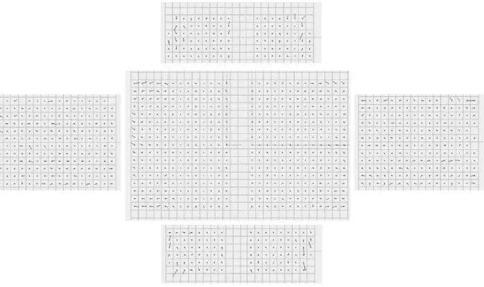
Figure 3: Image residuals of the full set of calibration images after the bundle adjustment. The sigma_o values (in micron) are 0.77 for the panchromatic nadir 1.79 for the oblique camera heads.
IMAGE QUALITY
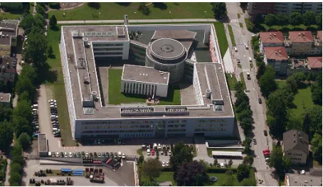
processing software adds the final polish to the image data, while always maintaining full image dynamic of 16-bit per color channel. In order to proof this image quality we show sample images from flight missions to highlight the quality of UltraCam Osprey production images. The samples shown below are taken from 900m above ground level (cf. Figure 4) and 500m above ground level (cf. Figure 5).
Figure 5: Large scale oblique left looking image at a GSD of approximately 5 cm (Gleisdorf, Austria).
UltraCam Osprey images have already been used for Microsoft-internal mapping projects. There images have been introduced into a digital workflow which leads into dense surface models as well as fully textured 3D models of urban environment (cf. Gruber, Walcher, 2013). Thus UltraCam Osprey did successfully show geometric and radiometric image quality which perfectly served for high quality photogrammetric production of value added data sets.
CONCLUSIONS
We have shown that the novel design of Microsoft’s UltraCam Osprey makes this camera system a fully capable photogrammetric aerial camera. While in the past oblique camera systems had played more of a niche role in aerial photogrammetry, there is now a high likelihood that the inherent advantages of oblique sensors - many looks at a pleasant 45-degree viewing angle - will soon find broader market acceptance. This is further helped by the superior flying efficiency of the UltraCam Osprey. At flying costs comparable to a traditional nadir-only camera system, the UltraCam Osprey is capable of delivering 5-look imagery of an area of interest while not compromising geometric quality at all. The inherent redundancy of UltraCam Osprey imagery makes it well suited for automated processing and feature extraction. It is therefore to be expected that soon there will be new software and processing tools to fully explore the multi-view imagery of this exciting new aerial camera system.
REFERENCES
Wiechert A., M. Gruber, 2009: Vexcel Imaging GmbH --- Innovating in PhotogrammetryUltraCamXp, UltraCamLp and UltraMap, Proceedings of the Photogrammetric Week 2009, Stuttgart, DE
Ladstaedter et al, 2010: Monolithic Stitching: One Sensor Geometry For Multiple Sensor Cameras, Proceedings of the American Society for Photogrammetry & Remote Sensing, 26-30 April, 2010, San Diego, CA
Wiechert A., M. Gruber, 2013: News from the UltraCam Camera LineUp, Proceedings of the American Society for Photogrammetry & Remote Sensing, 24-28 March, 2013, Baltimore, MD.