Designing and Manufacturing Quartz Crystal
Oscillators
Benfano Soewito1 1 Bina Nusantara University
Kebon Jeruk Raya No. 27, Jakarta, 11530 - Indonesia
Abstract. In this decade, the number of wireless devices grow significantly, caused the frequency stability is very important. Almost all wireless devices use the quartz crystal oscillator to generate stable frequency. To get good quality of quartz crystal oscillators, then it needs to be taken carefully from designing up to how to manufacture them. In this paper, we present the characteristic of quartz crystal oscillator and the factors that affect the frequency stability of quartz crystal oscillator. Knowing these factors to design crystal oscillator is es-sential. The characteristic of crystal oscillator will depend on the material puri-ty,cutting angle, dimension, surface roughness and edges, thickness, material of electrode, and cleanliness. Crystal oscillator manufacturing process is very long, starting from row material angle marking, cutting, shaping, lapping, elec-trode evaporation, mounting, frequency adjusting, and aging. All these process will discuss in this paper, including the testing.
1 Introduction
In this decade, the numbers of devices that use wireless technologies grow significant-ly. Starting from the most simple such as TV’s remote to highly complex equipment such as mobile phones or satellite. All these devices aim to transfer information or signals using radio waves. These radio waves have a frequency between 3 kHz to 300 GHz. Each range of frequency is used for specific purposes. For instance, 470 to 860 MHz for TV transmission, 1 to 2 GHz for GPS and mobile GSM phone, 2 to 4 GHz for wireless LAN and microwave ovens and so on. Because so many wireless devices, it is clear that the frequency stability is very important; if not there will be interfer-ence between the wireless devices. Almost all wireless devices use the quartz crystal oscillator to generate stable frequency. To get good quality of quartz crystal oscilla-tors, then it needs to be taken carefully from designing up to how to manufacture them.
crys-tal oscillator starting from growing quartz cryscrys-tal to final testing of quartz cryscrys-tal oscillator.
2 Background
In this section presents the background related to the quartz crystal oscillator. First we will introduce the piezoelectric material and theory then explaining the application of the quartz crystal in many areas.
2.1 Piezoelectric
The piezoelectric effect found in some material in which the material will generate the electricity charge when the mechanical stress applied to the material. Vice versa, if the electricity field applied to the material, the material response by mechanical strain. The effect of piezoelectric was introduces at the first time by Coulomb in the year 1815 [1], [2]. He had a hypothesis and theory that some material can generated elec-tricity when pressure applied on that material. Five year after Coulomb introduced his theory, and then Hauy and Becquerel tried to prove the Coulomb’s theory. His expe
r-iment support the Coulomb’s theory, he concluded that the electricity charge could be
generated by stretching rubber. In 1880, the brothers Pierre Curie and Jacques Curie proved the piezoelectric effect in crystalline minerals such as tourmaline, quartz, topaz, cane sugar, and Rochelle salt. They made experiment to apply mechanical stress to those crystalline minerals and measured the voltage from electrical charge that resulted by those crystalline minerals.
Since Curie brothers found the effect of piezoelectric then many research had been done in this area including the theory, model and experiment. In the beginning of the 19th century, Langevin started to make transducer from piezoelectric material. Until the frequency stability versus temperature change of quartz crystal oscillator was found by Born in 1933. Born found that the quartz crystal oscillator that made by 35 degree to the axis Z of quartz crystal had the best frequency stability to the tempera-ture change. He gave the name AT cut for angle cutting 35 degree. He also introduces the BT cut that had cutting angle of 49 degree. After this finding, all of the precision frequency control was made by quartz crystal oscillator.
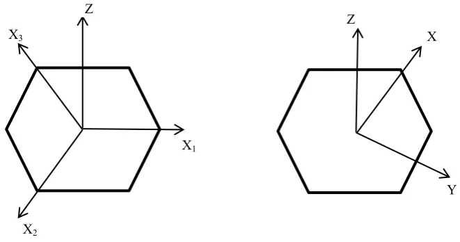
order to describe the characteristic of quartz crystal easier, then different axial sys-tems need to be familiarized. In figure 1, showed two coordinate axis system to ex-plain different properties of quartz crystal. The Bravais – Miller axis system was used to explain atomic system in quartz crystal. The Orthogonal axis was used to explain the piezoelectric and mechanical properties of quartz crystal.
Fig. 1. On left is Bravais – Miller coordinate axis system and on the right is Orthogonal coordi-nate axis system.
Basically the application of quartz crystal can be divided into several groups: Sen-sor (microphones, pressure senSen-sor, force senSen-sor, strain gauge), Actuators (loudspeak-er, piezoelectric motors, valves), Generator (energy harvesting, cigarette lighter), Transducer (ultrasonic sonar devices), and Frequency standard (oscillator).
2.2 Quartz Crystal Oscillator: History and Market
The research of quartz crystal oscillator initiated by A.M. Nicholson of the Bell Tele-phone Laboratories and W.G. Cady at Wesleyan University in 1917 [6]. Two year later, Cady used a quartz piezoid to control the frequency of an oscillator and in a series of papers during the next three years he described the use of quartz bars and plates as frequency standards and wave filters. It is generally accepted that Cady was the first to use a quartz piezoid to control the frequency of an oscillator circuit [6]. According to Virgil [6], Bell Telephone Laboratories established a quartz laborato-ry in 1923. And then one of individuals who recognized the potential of the quartz crystal unit was August E. Miller. Miller went to quartz crystal business, making quartz crystal oscillator for amateur radio operators. Quartz crystal was blank very expensive at that time. General Radio Company offered quartz crystal blank for sale at the price of $35 to $50. This was very large amount of money in 1925 [7]. Finally, in 1926, the AT&T radio station WEAF in New York City became the first radio station in the United States to control its frequency with a quartz crystal unit [8].
Efforts to develop a practical unit having a low frequency temperature coefficient were successful in 1934 when the AT and BT cuts were discovered independently by Koga from Japan, Bechmann and Straubel from Germany, and Lack, Willard, and Fair from United States [8].
According to Ji Wang [8], in 1943 there was 130 manufactures were engaged in the production of crystal units. They were scattered over 20 states from Oregon to Florida. Most of them were in the same area. There were twenty three factories that produced crystal units in Chicago, twenty in New York area, fifteen in Carlisle area, and fourteen in Kansas City area.
Quartz crystal unit market will be about more than 10 billion USD with growth rate of 7.5% annually. These because of more devices that work based on the wireless technique. In 2011, there are about 450 companies and suppliers globally that had business in quartz crystal units. 30% of crystal unit were installed in the telecommu-nication devices while the remaining 70% were installed in consumer electronics products. Japan is supplying the high-end products for telecommunications, while china is producing crystal units for the consumer markets with a global market share about 25% [8].
2.3 Quartz Crystal Synthetic
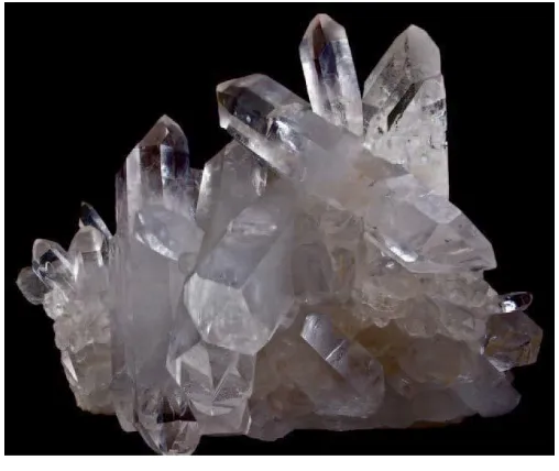
The quartz crystal is formed from silicon and oxygen, become SiO2 (silicon dioxide) as shown in figure 2 [10]. At the beginning of producing crystal oscillator in 1920s, the manufacturer used natural quartz crystal. Many disadvantages used natural quartz crystal to make quartz crystal units. The number of natural quartz crystal is very lim-ited and the purity is very low. The purity will have an impact to the impedance of quartz crystal unit and will drain the power resources. Besides that, the determination of axis is very difficult. All these make the price of crystal oscillator unit become very expensive in 1920s, $30 to $50 for a unit.
The research to make synthetic quartz crystal was started in the mid nineteenth century. The scientist attempted to create quartz crystal in laboratory with create the conditions in which the quartz crystal growth in nature. In 1845, the first person who tried to synthesize quartz crystal was a geologist, Karl Emil. He crated microscopic hexagonal quartz crystal in a pressure cooker for eight days. However, the quality and size of the crystals that were produced by these early efforts were poor [9]. Since 1930, all the telecommunications industry used the quartz crystal oscillator to control the frequency but the supply of quartz crystal is very limited. After the war many researcher and scientist attempted to make the synthetic quartz crystal. Finally in 1950s, synthetic quartz crystal were being produced and sold commercially.
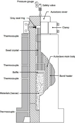
to 400 °C, respectively, the alkaline solution expands and is compressed; the pressure inside reaches 130 to 145 MPa.
Fig. 2. A cluster of natural quartz crystal. Adapted from the evolution of time measurement, part 2: Quartz Clocks by Michael A. Lombardi. In IEEE Instrumentation & Measurement Magazine, October 2011
Fig. 4. One Schematic depiction of synthetic quartz crystal growth. Adapted from Synthetic Quartz Crystal by Nihon Dempa Kogyo Co., LTD.
the degree of the temperature difference SiO2 is crystallized on the seed crystal [11]. The solution then returns to the lower compartment of the autoclave and dissolves the materials, thereby becoming the SiO2 saturated solution, and due to convection it raises and the cycle repeats. The repetition of this process leads to the successive growth of synthetic quartz crystals [11].
Manufacture crystal oscillator unit from the synthetic quartz crystal is easier than natural quartz crystal. Synthetic quartz crystal has high purity or almost 100% pure. The axes are already determined in the growth process and it is very helpful in cutting process. We can easy to make AT, BT cut or others cutting angle. Synthetic quartz crystal available globally, we can order as much as we need them with variety size.
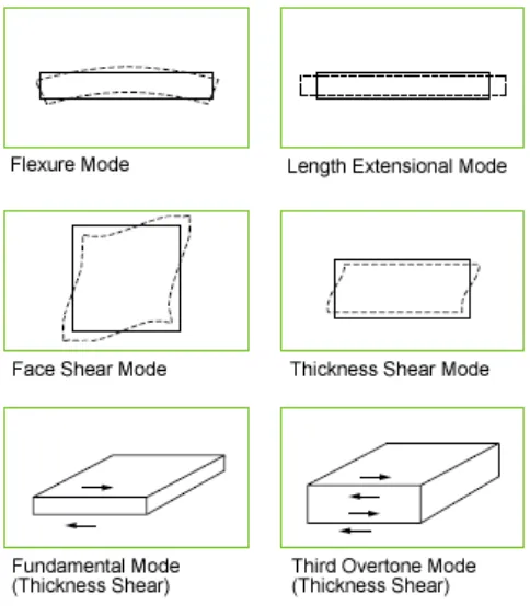
2.4 Thickness Vibration
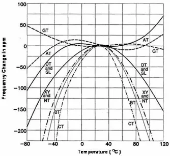
There are several vibration modes in quartz crystal oscillator as shown in figure 5. Each angle cut will has its own vibration mode. For example, quartz crystal oscillator with AT and BT cut have thickness shear vibration mode, and CT, DT, and SL cut have face shear vibration mode.
AT cut with thickness shear vibration mode can be vibrate from 0.5 – 300 MHz. The orientation cut angle of AT cut between 35o15’ to 35o18’ and BT cut is - 49o08’ against Z axis. CT, DT, and SL cut with face shear vibration mode can generate fre-quency 75 – 900 kHz. The orientation cut angle of CT, DT, and SL cut are 38o, -52o, and -57o consecutively.
3 Designing Quartz Crystal Oscillator
In designing quartz crystal oscillator, the first step is we have to know several elec-tronic parameters and the environmental condition where the oscillator will be placed. The electronic parameters that we have to know are frequency, maximum resistance, load capacitance, and frequency tolerance. The environmental condition that we have to know is the temperature range where the crystal oscillator will be operated.
Base on those information we can decide the angle cut of quartz crystal follow the graphic shown in figure 6.
The most popular quartz cut is AT cut, because the most stable frequency to tem-perature changing is AT cut. The frequency is depending on the thickness of quartz blank. We can follow the equation 1 to determine the thickness of quartz blank with AT cut. Different cutting has different coefficient cutting.
(1)
For example, to produce quartz crystal oscillator 10 MHz or the thickness 0.167 mm, we must cut the synthetic quartz crystal about 0.24 mm. After cutting process, they will be lapped to the frequency closed to 10 MHz or 0.167 mm.
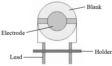
Next step is to determine the diameter of electrode. The electrode diameter depend on the load capacitance that the required by user. The load capacitance is an external capacitor in order to adjust the frequency to the specific frequency. It can put in paral-lel or series to the crystal unit.
Fig. 7. Inside view of crystal unit.
Crystal unit has equivalent circuit as shown in figure 8. The Co is a shunt capaci-tance represents the capacicapaci-tance of the crystal electrode including capacicapaci-tance of the crystal holder and leads. C1 is motional capacitance represents mechanical elasticity. L1 is motional inductance represents mechanical inertia. R1 is motional resistance represents mechanical losses.
Fig. 8. Equivalent circuit of crystal unit
The quality factor Q of a crystal unit as shown in equation 2 is the quality factor of the motional arm at resonance. The maximum stability that can be attained by the crystal unit is directly related to Q, the higher Q the smaller the bandwidth.
Electrode
Blank
(2)
4 Manufacturing Quartz Crystal Oscillator
The raw material for manufacturing quartz crystal unit is synthetic quartz crystal. Quartz crystal unit manufacturing process is very long process. The processes start with lapping process or grinding the surface of synthetic quartz crystal to final test.
4.1 Lumbering Synthetic Quartz Crystal
The lumbering synthetic quartz crystal is a process to grind the surface of synthetic quartz crystal. This process use abrasive green silicon carbide powder #500. There are two purposes of this process. Firstly, is to make the size of synthetic quartz crystal to be the same. Secondly, is to be easy to propagate the x-ray in the next process. After process lumbering, the synthetic quartz crystal become lumbered bar.
4.2 Lumbered Bar Cutting
A steel board was placed on the x-ray machine, and the lumbered bar will be placed on a steel board using UV silicon glue. The x-ray was used to determine the right position of cutting angle lumbered bar. Depending on the size of steel board, one steel board can accommodate 4 to 6 lumbered bar per layer and it can be 3 layers maxi-mum. After the lumbered bar placed in the right position then the steel board and lumbered bar will be placed in the UV lamp conveyor to dry the UV glue. Then the steel board and lumbered board placed on cutting machine. Normally, cutting ma-chine uses blade to cut the lumbered bar. It will take about 10 to 12 hours to cut three layer of lumbered bar.
4.3 Wafer Lapping
4.4 Dimensioning or Shaping
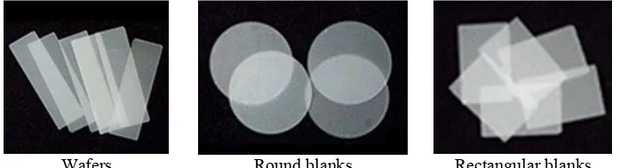
The next process is the process of dimensioning or shaping. In this process, wafers are shaped into a blank with the size and shape in accordance with the order. In this pro-cess wafers were stacked of one another and then glued together to form a wafer stick. Then the wafer stick is made round or cut according to the size of the order. After this process, the wafers quartz crystal become the blank quartz crystal. It can be round or rectangular as shown in figure 9.
Wafers Round blanks Rectangular blanks
Fig. 9. Wafers and blanks
4.5 Blank Lapping
In the blank lapping process, the thickness is no longer the target, but a frequency is a target, where the target frequency is in accordance with the order from user. In this case the thinner blank then the higher the frequency. The formula that connects be-tween the frequency and the thickness is shown in equation 1. Frequency [kHz] = 1670 / thickness [mm]. In the blank lapping process used green silicon carbon pow-der. If we want the crystal oscillator work on the overtone frequency, then after lap-ping used green silicon carbon, the blank have to be polished.
4.6 Etching
It may have particles of green silicon and oil still stick on the surface of blank. The purpose of etching process is to clean the surface of the blank from the particles and smoothing the blank surface. The etching process is done by immersing the blank in fluorite acid or HF acid solution for a few seconds.
4.7 Cleaning
minutes, depending on the thickness of the crystal blank to be washed and the number of blanks in the basket. When finished, the blank crystal soaked with alcohol and put them back to the ultrasonic machine in the basket with alcohol. After that, immerse the crystal blank with alcohol to absorb water. Once it’s dry so no water spots on the surface of the crystal blank. After that, the crystal blank is inserted directly to the oven with a temperature between 80 -110 degrees Celsius for one hour. Once out of the oven then the crystal blank is ready to the next process, which is base plating process. If the blank do not clean, it will increase the motional resistance.
4.8 Base Plating
In this process, blank is given electrode on both sides by using silver or gold. When using gold it will be more resistant to corrosion or rust. But generally use silver. Blank will be placed on the mask, and the mask is inserted into the machine base coating. The process of base plating uses an evaporation technique at low pressure or vacuum. Actually, this low pressure just to lower the melting point of silver or gold, beside to pull out the oxygen gas trapped in the base plating machine.
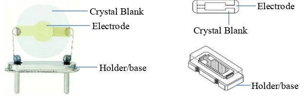
4.9 Mounting
Mounting is the process to place the blank on the holder as shown in figure 10. The holders depend on the type of crystal. Some holder for round blank and some for rectangular blank.
Round blank and holder Rectangular blank and holder Fig. 10. Crystal blank on the holder
4.10 Frequency Adjustment
4.11 Sealing
Sealing is process to cover crystal blank and holder. There are several techniques to seal between cover and holder. The most popular are resistance welding technique. Resistance welding is a process that use electrically to generated heat and force is applied to surface of material to bonds between holder and cover. The welding pro-cess is done in a chamber, fill in by nitrogen gas. The purpose of nitrogen is to pull out the oxygen gas, because the oxygen gas can make the electrode oxidation.
4.12 Final Test
The last process is final test. The quartz crystal unit is tested use the automated final test machine. Normally, the parameter which was measured as follow:
1. Frequency range.
2. Co (shunt capacitance), represents the capacitance of the crystal electrode in-cluding capacitance of the crystal holder and leads.
3. C1 (motional capacitance), represents mechanical elasticity. 4. L1 (motional inductance), represents mechanical inertia. 5. R1 (motional resistance), represents mechanical losses.
5 Conclusion
Stability frequency on wireless devices became very important, because more and more the wireless devices used in daily life. From simple equipment such as TV re-mote, AC remote to complex equipment such as cell phone, access point, etc. These devices will not be able to function properly when the frequency interfering between the devices. Crystal oscillator unit is an electronic component that is responsible for frequency stability. Therefore all steps and processes in designing and manufacturing crystal oscillator must be considered carefully.
Orientation of cutting angle is very critical to the stability of frequency to change of temperature. Quartz crystal unit with the AT cut has the most stable frequency compare to others cutting angle.
The motional resistance R1 will be higher if the surface of quartz blank is not clean or there are some particles on the surface. The higher motional resistance will need more energy to vibrate. In other word, it will drain the battery more if installed in the wireless devices.
References
1. Ballato, A. : Piezoelectricity: Old Effects and New Applications. IEEE Ultrasonics Transac tions, Ferroelectric Frequency Control, Vol. 42, (1995) 916–926
3. S. Fujishima : The History of Ceramic Filters. IEEE transactions on ultrasonics, ferroelec-trics, and frequency control, Vol. 47, no. 1 (2000)
4. Hewlett Packard : Fundamentals of Quartz Oscillators, Application Note 200-2, Electronic Counters Series, USA (1997)
5. Charles E. Worthen : Piezo-Electric Quartz Plates, The General Radio Experimenter, Vol. 4, no. 9 (1930)
6. Virgil E. Bottom : A History of The Quartz Crystal Industry in The USA. Proceedings of the 35th Annual Frequency Control Symposium, (1981) 3-12
7. Patrick R. J. Brown : The Influence of Amateur Radio on the Development of the Commer-cial Market for Quartz Piezoelectric Resonators in the United States. Proceedings of the IEEE International Frequency Control Symposium (1996) 58 – 65
8. Yook-Kong Yong and Ji Wang : Theory and Analysis of Quartz Crystal Resonators. A tuto-rial at the Joint Conference of the IEEE International Frequency Control Symposium and the European Frequency & Time Forum (2011)
9. Kazuo Moriya and Tomoya Ogawa : Growth History of a Synthetic Quartz Crystal. Journal of Crystal Growth, vol. 58, issue 1, (1982) 115-121
10. Michael A. Lombardi : The Evolution of Time Measurement, Part 2: Quartz Clocks. In IEEE Instrumentation & Measurement Magazine, page 41 - 48 (October 2011)
11. Nihon Dempa Kogyo Co., LTD : Synthetic Quartz Crystal. Retrieved from