1
INFLUENCE OF TIME AND CONCENTRATION ON TEXTURAL
PROPERTIES OF MESOPOROUS CARBONS OF GELATIN
PREPARED BY HARD-TEMPLATING PROCESS
1
Department of Chemistry Education, Faculty of Teacher Training and Education Sebelas Maret University
Ir. Sutami Street 36A Surakarta, Center of Java, Indonesia 57126 2
Department of Chemistry, Faculty of mathematics and natural sciences Gadjah Mada University
Sekip Utara street, Yogyakarta, Center of Java, Indonesia 55281
ABSTRAK
Karbon mesopori dengan sifat tekstural yang berbeda dibuat dari gelatin melalui proses cetakan padat. Pengaruh kondisi pelepasan silika (waktu dan konsentrasi asam) pada sifat nanokomposit telah dipelajari selama proses sintesis. Waktu pelepasan silika yang dipilih adalah 1, 6 dan 24 jam menggunakan konsentrasi HF 10%, 20%, 30% dan 40%. Sifat tekstural dan mikrostruktur nanokomposit telah dikarakterisasi menggunakan difraksi sinar X dan mikroskop transmisi electron, spektroskopi energy dispersive sinar-X dan adsorpsi desorpsi N2. Hasil menunjukkan bahwa waktu saat proses pelepasan silika menyebabkan nukleasi dan pertumbuhan karbon mesopori pada permukaan. Semakin menurun waktu pelepasan silika dna konsetrasi HF maka menyebabkan semakin meningkatnya luas permukaan dan volume total karbon dari 410 hingga 760 m2/g dan 0,14–0,99 cm3/g dengan rata-rata diameter pori yang hampir sama yaitu 4,1 nm. Selanjuntya, telah teramati adanya lebih banyak distribusi pori homogen dengan semakin menurunnya waktu pelepasan silika dan konsentrasi HF. Kesimpulannya adalah waktu pelepasan silika dan konsentrasi asam memegang peranan penting pada sifat tentural karbon mesopori dimana hal ini memberi pengaruh besar dalam performa adsorpsi senyawa sulfur dalam minyak bumi.
Kata kunci:karbon mesopori, pelepasan silika, waktu, konsentrasi asam
ABSTRACT
Mesoporous carbons with different textural properties were prepared with gelatin by hard templating process. The effect silica removal condition (time and acid concentration) on the nanocomposite properties was studied during synthesis process. 1, 6, and 24 h silica removal times and 10%, 20%, 30% and 40% HF concentraton were chosen. Textural properties and microstructure of the nanocomposites were characterized by X-ray diffraction (XRD), Transmission Electron Microscopy (TEM), Energy Dispersive X-ray Spectroscopy (EDAX), and N2 adsorption– desorption. Results showed that removal silica time process led to mesoporous nucleation and growth on the surface of mesoporous carbon. At decreasing of removal silica time and HF concentration the surface area and total pore volume increased from 410 to 760 m2/g and 0.14–0.99 cm3/g with almost same of the average pore diameter considerably at 4.1 nm. Furthermore, it was observed more homogeneous pore distribution with decreasing the silica removal time dan HF consentration. In conclusion, the silica removal time and acid concentration play an important role on textural properties of mesoporous carbon which could have a major effect on adsorption properties of sulfuric compound in the fuel.
Key Word:mesoporus carbon, silica removal, time, acid concentration ũŬƉŬ
http://jurnal.fkip.uns.ac.id/index.php/ e-ISSN xxxx-x
* Corresponding author, Tel/Fax (0274)545188, e-mail: [email protected]
Maria Ulfa
1*, Wega Trisunaryanti
2, Iip Izul Falah
2and Indriana Kartini
2INTRODUCTION
Sulfuric compounds in the fuel have
many problems on the environment [1]. The
removal of sulfur is carried out through
desulfurization. Adsorption is a favourable
process for fuel desulfurization [2].
Mesoporous carbons have high adsorption
capacity due to large specific surface area,
high order structure and mesoporosity. The
use of microporous adsorbents such as
activated carbons, clays, metal oxides and
supported metals (often in combined
formulations) for the removal of diverse
sulphur compounds from various streams is
documented in several report [4–6]. It was
reported that microporous adsorbed an
small amount of sulfuric compund [13]. A
good adsorption performance was linked to
the development of mesoporosity. The
mesoporous material speed up the
adsorption rate of sulfuric compound due to
the large pore and high total volume.
Some researchers have carried out
the synthesis of mesoporous carbon by the
hard templatel method [7-9]. The synthetic
routes of hard templating process based on
the infiltration of carbon precursor the use
pore of inorganic solids. A number of carbon
precursor as sucrose, gliserol, aromatic
polyamides and poly(vinylidene
chloride-co-vinyl chloride)[10-13]. New precursors from
low cost materials are needed in order to
produce mesoporous carbons. Our research
has been working on gelatin as precursor
carbon due to high carbon and posses the
amino functional groups which can strongly
interact with silica species by hydrogen
bonds [14-15].
The synthesis of mesoporous carbon
was performed by infiltration of carbon
precursor onto solid matrix, carbonization
and removal solid template by dissolving in
HF. The obtained carbons are either the
replica of the template or exhibit a new
structure [16]. The unfilled template pores
produce new pore system of the
mesoporous carbon. Previous research
report that removal solid template with HF
caused starting formation of new pore
systems (Kerstin). The physical and
chemical processes during on pore
formation of mesoporous carbon with HF is
importance to understand. However,
information of the effect of HF treatment
condition to textural properties of
mesoporous carbonis very rare in the
literature. In this study, mesoporous carbons
(MC) were prepared from gelatin. The
development of the textural and stucturel
properties of mesoporous carbon during
silica removal with HF have been
investigated in detail of time and
concentration. Characterization of
meso-porous carbon using nitrogen gas
adsorption, SAXRD and TEM.
II. EXPERIMENTAL SECTION
2.1. Preparation of mesoporous carbons
Mesoporous carbon material was
synthesized by using SBA-15 mesoporous
material as a silica template (particle size
0,1 μ m, pore diameter 7-8 nm, surface area
550 m2/g, pore volume 1,0 cm3/g) and
gelatin as the carbon source which extracted
from Javanese cow bone as previous report
[14-15]. The step of synthesis of
(mesoporous silica material) was added to a
solution obtained by dissolving 1 g of gelatin
and 0.13 g of H2SO4 in 6 g of water, and
keeping the mixture in an oven for 7 h at 110
°C. Subsequently, the oven temperature
was raised to 150 °C for 7 h. In order to
obtain fully polymerized and carbonized
gelatin inside the pores of the silica
template, 0,5 g of gelatin, 0.11 g of H2SO4
and 5 g of water were again added to the
pre-treated sample and the mixture was
subjected to the thermal treatment described
above. The template–polymer composites
were then pyrolyzed in a nitrogen flow at
900 °C and kept under these conditions for 3
h to carbonize the polymer.
a. Variation of HF treatment time
The silica-carbon composites from
sample were stirred 200 rpm with 5% HF to
remove the silica template by variation of the
treatment time at 1, 6 and 24 h. Finally, the
obtained carbon material was washed with
distilled water and dried in air at 110 °C for
24 h. The The resulted sample has been
denoted as OMCG-nh, with n represent of HF treatment time.
b. Variation of HF concentration
The concentration of HF in the
dissolving solution was varied from 10% up
to 40% for 1 h. The resulted carbon material
was washed with distilled water and dried in
air at 110 °C for 24 h. The obtained sample
has been denoted as OMCG-HFm%, with m represent of HF concentration.
2.2. Characterization
Nitrogen adsorption and desorption
isotherms were measured on a
Quantachrome Autosorb 1 sorption
analyzer. All samples were outgassed at
300 °C for 3 h prior to the nitrogen
adsorption measurements. The specific
surface area was calculated using the
Brunauer–Emmett– Teller (BET) method.
The pore size distributions were obtained
from the adsorption branch of the nitrogen
isotherms by Barrett–Joyner–Halenda
method. The ordering of mesoporous carbon
mesostructure analyze using small-angle
powder X-ray diffraction (SAXRD) pattern.
Sample was recorded with a Bruker D4
powder X-ray diffractometer (Germany)
using Cu Ka radiation (40 kV, 40 mA) with
0.02◦ step and 4 s/◦ scanning rate within
0.02◦ < 2θ < 5◦ range. The measurements
were conducted under a nitrogen
atmosphere. An empty pan was used as a
reference. The morphologies of all the
synthesized samples were characterized by
a transmission electron microscopy (TEM)
instrument (Philips CM30) operating at 120
kV. Each sample was dispersed in absolute
ethanol and a drop was placed on a Cu grid
covered with perforated carbon film.
RESULT AND DISCUSSION
a. Effect of HF treatment time
Fig.1 was the nitrogen sorption results
which showed typical type IV isotherm with
type H2 hysteresis loop, concluding that this
material has cylindrical pore channels type.
The nitrogen sorption isotherm in low P/Po
range of 0.0–0.1 indicates that large
carbon porewall. All isotherms sample at
relative pressure (P/Po) more than 0.35
exhibit a sharp step characteristic of
capillary condensation of nitrogen within
uniform mesopores. The diameter of the
mesopore represented by the inflection point
of the p/po position [18].
Fig.1. Nitrogen adsorption–desorption isotherms of mesoporous carbon materials treated at different time of removal silica
Fig. 2. Curve of t-plot mesoporous carbon materials treated at different time of removal silica
Fig. 2 exhibits the t-plot of all sample
by Harkins and Jura equation which is the
intercept and the slope of the linear fit
represent micropores and surface area.
OMCG-6h shows higher micropore than
other sample. Precursor carbon during
carbonization loss hydrogen, oxygen and
nitrogen atoms, if present, that can create a
microporosity [19]. Removal silica for longer
time can cause slower diffusion generating
microporosity of carbon. This fact is due not
only to molecular size, but also to the affinity
of fluorin ion with the silica matrix. The result
implies that a longer time during removing
silica could enhance micropores due to
small pore originate from diffusion effect.
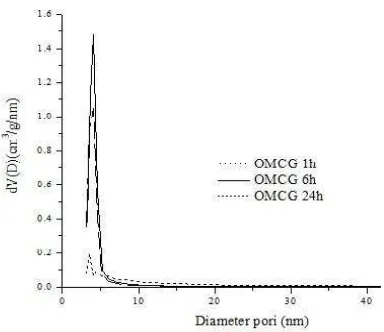
Fig. 3. BJH adsorption pore size distribution of mesoporous carbon treated at different time of removal silica
Fig. 3 shows the adsorption pore size
distribution of all sample treated by HF at
different time. All sample show uniform pore
size distribution which possesses narrow
pore size distribution. The calculated pore
diameters of the all the samples are in the
range of 4.0 up to 5.2 nm. In addition, no
clear trend in the pore diameter versus the
degree of pore filling is observed.The
adsorption pore size distribution curve
combined with particle size distribution
extracted from TEM image (Fig. 4) indicates
that all sample has uniform pore size.
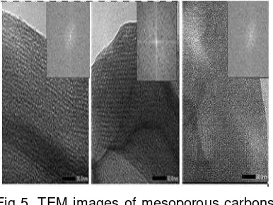
Fig 5. shows the TEM image of all
sample which is clearly exhibited an ordered
Fig. 4. Hystogram of TEM particle size distribution of mesoporous carbon treated at different time of removal silica
Fig 5. TEM images of mesoporous carbons after removal silica for a. 1h; b.6h and c. 24 h.
mesopores separated by carbon walls and
some carbon deposits on the external
surface. The structural order of the materials
treated with HF at different time show
significant differences. It is also interesting
to follow changes in the structure of carbon
materials treated with HF at different time.
OMCG-1h shows mesoporous channels with
a small disordered mesoporous structure
because of the incomplete silica removal.
OMCG-6h exhibited a highly ordered
mesoporous structure with linear array of
mesopores from the mesoporous silica
framework after the HF treatment for 6 hour.
The longer time probably enough to ensure
complete removal of all silica speciel from
composite. In contrast, OMCG-24 show
decreasing mesopores strucuture that
mainly due to the shrinkage effect during
longer dissolving time.
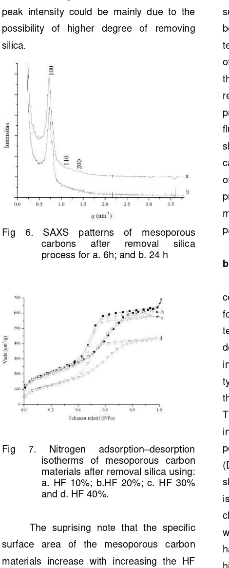
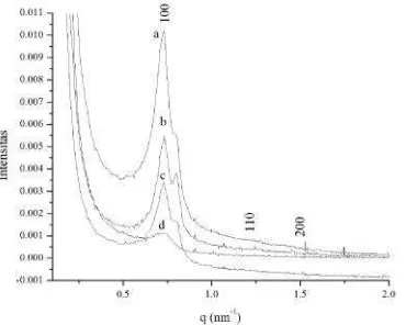
Fig. 6 shows the small angle X-ray
scattering patterns of mesoporous carbon
materials prepared at different template
removal time. All the samples except exhibit
a sharp diffraction peak at low angle and two
higher order peaks which can be indexed to
the (100), (110) and (200) reflections of the
hexagonal space group p6mm with qvalue at 0.72; 0.79; dan 1.09. This indicates that
all the materials possess hexagonally
ordered uniform mesoporous structure with
long range order [20] The hexagonal unit
cell a0 parameter is calculated using the for
The intensity of the (100) diffraction peaks of
the samples, namely, OMCH-6h is much
higher as compared to the samples treated Table 1. Textural parameters of mesoporous carbon materials after removal silica at
different condition
Sample SBET
(m2/g)
Sme
(m2/g)
% me Vt
(cm3/g)
Da
(nm)
Db
nm)
ao
(nm)
t
(nm)
OMCG-1h 536 443 83 0,52 3,5 3,5 TD TD
OMCG-6h 756 636 85 0,99 5,2 4,3 10,53 5,43
with HF for longer time. The reduction in the
peak intensity could be mainly due to the
possibility of higher degree of removing
silica.
Fig 6. SAXS patterns of mesoporous carbons after removal silica process for a. 6h; and b. 24 h
Fig 7. Nitrogen adsorption–desorption isotherms of mesoporous carbon materials after removal silica using: a. HF 10%; b.HF 20%; c. HF 30% and d. HF 40%.
The suprising note that the specific
surface area of the mesoporous carbon
materials increase with increasing the HF
time treatment for 1 and 6 h but decrease at
24 h (Table 1). The specific surface area
amounts to 536 m2/g for OMCG-1h and
increases to 756 m2/g for OMCG-6h. The
higher surface area of OMCG-6h could be
attributed to increase in heterogeneity of
surface and micropores in the materials
because of the complete removing of silica
template in carbon pore. The pore thickness
of OMCG-6h higher than OMCG-24h due to
the shrinkage phenomenon during silica
removal. The longer time of dissolving silica
probably would enhance the interaction of
fluorin ion with species silica that caused
shrinkage of carbon channels. In addition
can be concluded that an optimized control
of time during silica removal is needed to
preserve the high ordering structure of
mesoporous of carbons with good textural
parameters.
b. Effect of HF concentration
Information about the optimal
concentration of HF is necessary in order to
form stable and defined pore structures after
template removal. The nitrogen adsorption–
desorption isotherm for all sample is shown
in Fig. 7. The isotherms are essentially of
type IV with a hysteresis loops that indicate
the sample have mesoporous type [21-22].
The corresponding textural parameters,
including specific surface area (SBET), total
pore volume (Vt) and average diameter pore
(D) values are presented in Table 1. The
sharp inflection of the mesoporous carbon
isotherm in P/P0 range from 0.5 to 0.7 is
characteristic of capillary condensation
within uniform pores. This mesoporous silica
has a steep nitrogen uptake at relatively
high P/Po due to its large uniform
mesopores and narrow pore size distribution
(PSD) centered at 3.5 up to 4.8 nm (Fig. 8).
The hysteresis loop of OMCG-10%
shifts to lower pressure from OMCG-20%
sample at low HF concentration compared
to the sample treated at higher
concentration. This is to be expected,
because the relatively wide pores of
OMCG-10% have been replaced with carbon
nanopipes. This mesoporous carbon shows
a relatively uniform pore size with maxima
around 4.8 nm (Table 1). The nitrogen
adsorption isotherm for OMCG-10% sample
exhibits relatively high adsorption at low
pressures, indicating the presence of
micropores. The increasing HF
concentration systematically decrease the
surface area of all sample. The
OMCG-HF10% exhibits considerably higher surface
area (756 m2/g, Table 1) compared to
OMCG-HF 20% (740 m2/g) due to more void
spaces generated after treated at high HF
concentration.
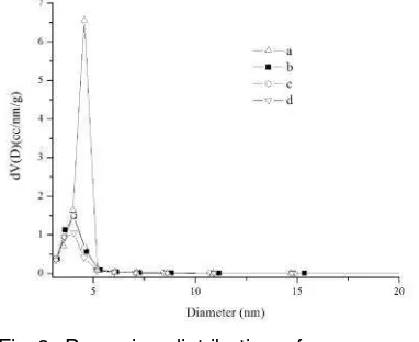
Fig 8. Pore size distribution of mesoporous carbon materials after removal silica using: a. HF 10%; b.HF 20%; c. HF 30% and d. HF 40%.
In Fig. 8 the pore size distribution of
the carbon materials on the HF
concentration in the synthesis solution is
shown. If the concentration of HF used for
silica removal is too high, huge parts of the
silica molecule remain removed and no
stable carbon walls will be formed. After
template removal, one can obtain either a
non-porous carbon or a carbon material
which exhibits a narrow pore size
distribution. The carbon composite treated
by 10% HF concentration shows a pore size
distribution with one maximum at about 4.5
nm.
Fig 9. t-plot curve of mesoporous carbon materials after removal silica using: a. HF 10%; b.HF 20%; c. HF 30% and d. HF 40%
Fig. 9 shows t-plot of sample treated with different HF concentration. T-plot
determine that surface area of
OMCG-HF10% is higher than the other sample due
to a lot of micropore generate on the
surface. In contrast, surface area of
OMCG-HF 40% lower than OMCG 10% that mainly
caused by increasing speed of silica
dissolution. The high speed of silica removal
probably produce disorder carbon that
increasing macroporous site whereas
decreasing surface area. It is can conclude
that HF concentration influence the textural
parameter of mesoporous carbon.
Fig. 10 shows SAXS pattern of
mesoporous carbon after treated in different
HF concentration. The resulting SAXS
pattern for OMCG-HF10%, obtained in the
2h range of 0.05–4°, together with those of
Fig 10. SAXS scattering of mesoporous carbon materials after removal silica using: a. HF 10%; b.HF 20%; c. HF 30% and d. HF 40%
comparison. All sample of mesoporous
carbon displays three well resolved peaks
indexed as (100), (110) and (200),
characteristic of the two-dimensional
hexagonal space group p6mm [40]. The
SAXS patterns of the resulting mesoporous
carbon also show ordered mesostructures
with p6mm symmetry, as evident from the
presence of (100), (110) and (200)
reflections, indicating that they have retained
the ordered structure of their parent silica
template [23-25]. As shown in Fig. 10, the
diffraction peaks of the mesoporous carbons
are slightly shifted to higher 2h values,
which can be related to smaller d-spacings
as well as smaller cell parameters.
The unit cell parameters for OMCG
treated with HF 10% up to 40% were 10.20;
10,14; 10,05 and 10.00 nm, respectively
(Table 1). The unit cell parameter of
OMCG-10 is higher than the silica other sample
which probably results from low structural
shrinkage of the carbon/silica composite
material during pyrolysis at high
temperature. Weaker (100) peaks of
OMCG-30% and OMCG-HF40% compared to
OMCG-10% are also the result of structural
shrinkage, which cause some decrease in
the structural ordering of the carbon
replicas. Structural shrinkage also results in
poor resolution of the (110) and (200)
diffraction peaks of the mesoporous carbons
Fig. 11 TEM image of mesoporous carbon materials after removal silica using: a. HF 10%; b.HF 20%; c. HF 30% and d. HF 40%.
Fig. 11 shows the TEM image that
represent morphologies of the synthesized
mesoporous carbon samples. The images
confirm the results obtained from SAXS and
N2 adsorption. The mesoporous carbon
OMCG-HF10% shows a well ordered
hexagonal structure in which ordered arrays
of the carbon nanopipes are separated by
ordered arrays of mesoporous tubes,
demonstrating the existence of the bimodal
pore system. As shown in Fig. 11, the single
types of pores systems can be clearly
identified in the structure of OMCG-HF10%,
corresponding to the tube pores left by
removing the silica template. From the TEM
image of OMCG-HF1-%, the average pore
is higher than other sample in different HF
concentration. TEM show that larger of
stacking faults of OMCG-HF40% as effect of
increasing removal template. It is implies
that disordered structure can occur if
removal template process on high speed. All
mesoporous carbon sample show that
relusting carbon not significant differ with
previous research.
CONCLUSION
In order to get the information about
structure stability of nanosized mesoporous
carbon particles, HF in different time and
concentration of was used to remove the
silica particles from composite mesoporous
carbon. Results showed that HF 10% at 1
hour was effective to improve the removal of
nanosized silica particles when the proper
amount added. Pore volume and BET
surface area of mesoporous carbon
increased up to 0.999 cm3/g and 756 m2/g,
respectively after the removal process with
HF 10%. The HF used in the present study
Indonesian Ministry of Education through the
Scholarship of Perguruan Tinggi Universitas
Gadjah Mada by Beasiswa Unggulan
program 2012 (DIKTI) was gratefully
acknowledged. 2011, Chemical Engineering Journal, vol. 166, no. 1, pp. 207–217, Jan.
[3] B. S. Liu, Z. Y. Wan, Y. P. Zhan, and C. T. Au, 2012, Fuel, vol. 98, no. 3, pp. 95–102, Aug.
[4] X. Ma, S. Velu, J. H. Kim, and C. Song, 2005, Applied Catalysis B: Environmental, vol. 56, no. 1–2, pp. Song, 2006, Catalysis Today, vol. 111, no. 1–2, pp. 74–83, Jan. Chih-Yuan, Tang, 2006, Microporous and Mesoporous Materials, vol. 93, pp. 344–348.
[10] J. Jin, N. Nishiyama, Y. Egashira, and
K. Ueyama, Microporous and
Mesoporous Materials, vol. 118, no. 1–3, pp. 218–223, 2009.
[11] K. Bo, W. Einicke, and O. Klepel, 2005.Carbon, vol. 43, pp. 1918–1925, [12] J. Choma, A. Zawi, and J. Górka,
2009, Carbon 167–171.
[14] M. Ulfa, W. Trisunaryanti, I. I. Falah, and I. Kartini, 2014, Journal of Chemical Engineering and Chemistry Research, vol. 1, no. 2, pp. 101–109. [15] M. Ulfa, W. Trisunaryanti, I. I. Falah,
and I. Kartini, 2014,Journal of Applied Chemistry, vol. 4, no. V, pp. 1–7. [16] M. Ulfa, W. Trisunaryanti, I. I. Falah,
and I. Kartini, 2014, International Journal of Innovation and Applied Studies, vol. 7, no. 3, pp. 849–856. [17] R. Zhang, B. Tu, and D. Zhao, 2007,
Carbon, 373–376.
[18] W. Zhang, Y. Shan, and A.
Seidel-Morgenstern, 2006, Journal of
chromatography. A, vol. 1107, no. 1– 2, pp. 216–25.
[19] Mario Beretta, Thesis, University of Milano - Bicocca, 2009.
[20] H. Lin, C.-C. Chun-Yi, and C.-Y. L. Chih-Yuan, Tang, 2006, Microporous and Mesoporous Materials, vol. 93, pp. 344–348.
[21] N. On, B. Char, and O. 1945, Carbon, vol. 35, pp. 285–307.
[22] S. Naumov, P. Gutachter, and K. E. Gubbins, “Hysteresis Phenomena in Mesoporous Materials,” 2009.
[23] H. Lin, C.-C. Chun-Yi, and C.-Y. L. Chih-Yuan, Tang, 2006, Microporous and Mesoporous Materials, vol. 93, pp. 344–348.
[24] A. E. Hodgkins, R. P. Sen, and T. Anderson, 2004.Studies in Surface Science and Catalysis, vol. 154, pp. 400–407.