EQUILIBRIUM STABILITY OF A SERVO ACTUATING FLIGHT CONTROLS IN A SERVOELASTIC FRAMEWORK
Ioan Ursu, Felicia Ursu, Andrei Halanay, Carmen Anca Safta
Abstract. The mounting structure stiffness’s effects on mecanohy-draulic servomechanisms actuating aicraft’s primary flight controls are mod-eled as a system of ordinary differential equations. Stability analysis of equi-libria reveals the presence of a critical case that is handled through the use of the Lyapunov-Malkin theorem. Stability charts are drawn using the Routh-Hurwitz criterion for stability polynomial and it is shown that the stability of the system can be ensured exploiting positive influence of structural feed-back.
2000 Mathematics Subject Classification: 34H05, 34D20. 1. Introduction
2.The mathematical model
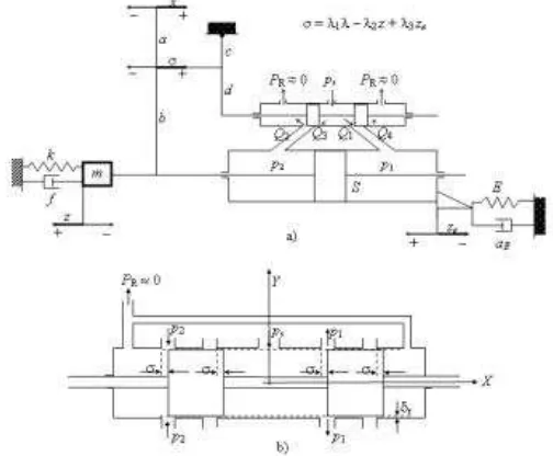
[image:2.612.161.413.233.441.2]In Figure 1, a typical physical model of an MHS in the servoelastic frame-work is shown, defined by considering the mounting structure stiffness E. MHS is in fact a combination spool valve (SV)-hydrocylinder (HC) with pis-ton. The first equation of the SV-controlled piston is obtained based on the fact that the flow into and out of the cylinder is described by two compo-nents, one being due to the movement of the piston and one to compressibility effects: for the case σ > 0
Figure 1: Physical model of a typical MHS: a) spool valve, cylinder with piston, feedback linkage, load, mounting structure; b) ideal ”two-land-four-way” spool valve
cdwσ s
2(ps−p1)
ρ =S( ˙z−ze) +˙
V +S(z−ze) B p˙1,
−cdwσ r
2p2
ρ =−S( ˙z−ze) +˙
V −S(z−ze) B p˙2
and similarly, ifσ < 0
cdwσ r
2
ρp1 =S( ˙z−ze) +˙
V +S(z−ze) B p˙1,
−cdwσ s
2(ps−p2)
ρ =−S( ˙z−ze) +˙
V −S(z−ze) B p˙2.
(2.1′
)
The parameters are: cd - volumetric flow coefficient of the valve port; w - valve-port width; ps - supply pressure; ρ - volumetric density of oil; V -cylinder semivolume; B - bulk modulus of the oil. The variables are: p1 and p2 - hydraulic pressures in the chambers of the HC;σ - relative displacement spool-sleeve; z - load displacement;ze - mounting structure displacement.
The equation of motion of the piston assembly is a force balance equation mz¨+fz˙+kz =S(p1−p2) (2.2) The dynamics of the feedback deflection ze is given by an equation in-volving the stiffness E, an equivalent mass me and a damping coefficient ae
meze¨ +aeze˙ +Eze=−S(p1−p2). (2.3) An algebraic equation, the feedback linkage equation, completes the differ-ential algebraic mathematical model. It is the equation of the valve opening σ viewed as a linear superposition of three small succesive displacements of input displacement x, output feedback response variable z and feedback deflection ze induced by structural feedback
σ=λ1x−λ2z+λ3ze (2.4) λ1 =
b(c+d)
c(a+b), λ2 =
a(c+d)
c(a+b), λ3 = c+d
c . The following limitation is to be considered
|x|< xM. (2.5)
To equations (2.1)-(2.4) corresponds a six-dimensional system of ordinary differential equations that describes the evolution of the servomechanism for σ >0. Let
C =cdw r
2
ρ (3.1)
and introduce the following state variables
x1 =z, x2 = ˙z, x3 =ze, x4 = ˙ze, x5 =p1, x6 =p2 (3.2) (2.1)-(2.4) give
˙ x1 =x2
˙ x2 =−
k mx1−
f mx2+
S
m(x5−x6) ˙
x3 =x4 ˙ x4 =−
E mex3−
ae mex4 −
S
me(x5−x6) ˙
x5 =
BS V +S(x1−x3)
C
S(λ1x−λ2x1+λ3x3)
√
ps−x5−x2+x4
˙
x6 = − BS V −S(x1−x3)
C
S(λ1x−λ2x1+λ3x3)
√
x6−x2+x4
(3.3)
Equilibria (ˆx1,xˆ2,xˆ3,xˆ4,xˆ5,xˆ6) satisfy ˆx2 = 0, ˆx4 = 0 and kxˆ1−S(ˆx5−xˆ6) = 0
Exˆ3+S(ˆx5−xˆ6) = 0 λ1x−λ2xˆ1+λ3xˆ3 = 0
(3.4)
So ˆ x1 =
Eλ1x Eλ2+kλ3
, xˆ3 =− k
Exˆ1, xˆ2 = ˆx4 = 0, xˆ5 = ˆx6+ k S
Eλ1x Eλ2+kλ3
(3.5) where ˆx5,xˆ6 ∈(0, ps).
Translate such an equilibrium point (ˆx1,0,xˆ3,0,xˆ5,xˆ6) given by (3.5) to origin through
y1 =x1−xˆ1, y2 =x2, y3 =x3−xˆ3, y4 =x4, y5 =x5−xˆ5, y6 =x6−xˆ6 (3.6) and introduce also
ˆ
The new system will be ˙
y1 =y2 :=f1(y1, . . . , y6) ˙
y2 =−k my1 −
f my2+
S
m(y5−y6) :=f2(y1, . . . , y6) ˙
y3 =y4 :=f3(y1, . . . , y6) ˙
y4 =− E mey3−
ae mey4−
S
me(y5−y6) :=f4(y1, . . . , y6) ˙
y5 =
BS
V +S(y1−y3+ ˆx0)×
−C
S(λ2y1−λ3y3) p
ps−y5−xˆ5−y2+y4
:=f5(y1, . . . , y6) ˙
y6 =
BS
V −S(y1−y3+ ˆx0)×
C
S(λ2y2−λ3y3) p
p6+ ˆx6+y2−y4
:=f6(y1, . . . , y6)
(3.8)
To investigate Lyapunov stability of the zero solution in (3.8) the starting point is the computation of the Jacobian matrix in 0, A = [aij]. Observe that
a51 = ∂f5 ∂y1
(0) =−BCλ2
√
ps−xˆ5 V +Sx0
; a52=− BS V +Sx0
; a53=
BCλ3
√
ps−xˆ5 V +Sx0
, a54=−a52, a55 =a56 = 0
(3.9)
and
a61= BCλ2
√
ˆ x6 V −Sx0
; a62 = BS V −Sx0
; a63=−BCλ3
√
ˆ x6 V −Sx0
; a64 =−a62; a65=a66 = 0
It follows that A=
0 1 0 0 0 0
−mk −mf 0 0 S
m −
S m
0 0 0 1 0 0
0 0 −E
me − ae me − S me S me a51 a52 a53 a54 0 0 a61 a62 a63 a64 0 0
(3.11)
The characteristic polynomial of A is
P(λ) = λP1(λ) (3.12)
The approach in [5] leads to the following result on stability. Its proof is presented in [6].
Theorem 3.1. If P1 in (3.12) is a stable polynomial, equilibria given in
(3.5) are Lyapunov stable. When initial conditions are close enough to the equilibrium point the asymptotic behaviour of the solutions is given by
lim t→∞x
1(t) = ˆx1, lim t→∞x
2(t) = 0, lim t→∞x
3(t) = ˆx3, lim t→∞x
4(t) = 0, lim
t→∞x
5(t) = ˆx5+ α 1 +d5
, lim t→∞x
6(t) = ˆx6+ α 1 +d5
.
(see [6] for the definitions of d5 and α).
4. Numerical results
Consider the following values of the system’s parameters: m = 30kg -equivalent inertia load of primary control surface reduced at the hydraulic servo’s piston rod; me = 2kg - equivalent inertia of hydraulic servo body and attached neighbour structure; k = 105
N/m - equivalent aeromounting structure elastic force coefficient; f = 3× 10³
N s/m - equivalent viscous friction force coefficient; ps = 2×10⁷
N/m2
- supply pressure to valve; pR≈0 - return pressure; S = 10−3
m2
- piston area; xM = 0.03m - half of piston stroke [m]; V = 3×10⁻⁵
m3
- semivolume of oil under compression in both cylinder chambers [m3
], V :=S×xM; B = 6×10⁸ N/m2
- bulk modulus of oil; w = 8.5×10⁻⁴
m - area gradient of valve [m2
cd = 0.6 - valve discharge coefficient; λ1 = 2
3, λ2 = 2
3, λ3 = 4
3 - kinetic feedback coefficients; ρ = 850kg/m3
- oil density; kQp = flow-pressure gain
[m5
/N s]; kQ = valve flow gain [m2 /s].
Usual values of structural damping ae are given in the literature ([3], [7], [8]) as corresponding to 2% of critical damping ratio so ae= 0,04√Eme.
Introduce p∈(0,1) by
ˆ
x6 =pps (4.1)
By the Routh-Hurwitz criterion ([9]) a necessary and sufficient condition that the polynomial
P1(λ) = λ 5
+ 5 X
j=1
aj(p, x)λ5−j
in (3.12) be stable is that the principal minors of the Hurwitz matrix be positive. Thus we must verify:
∆1 =a1 >0 and this is indeed the case since a1 = f m
∆2(p, x) =a1a2(p, x)−a3(p, x)>0 (4.2) ∆3(p, x) = a1a2(p, x)a3(p, x) +a1a5(p, x)−a3(p, x)
2
−a2
1a4(p, x)>0 (4.3) ∆4(p, x) =a4(p, x)∆3(p, x)−a5(p, x)[a1a2(p, x)
2
+a5(p, x)−
−a1a4(p, x)−a3(p, x)a2(p, x)]>0 (4.4)
a5(p, x)>0 (4.5)
(note that ∆5 =a4/∆4).
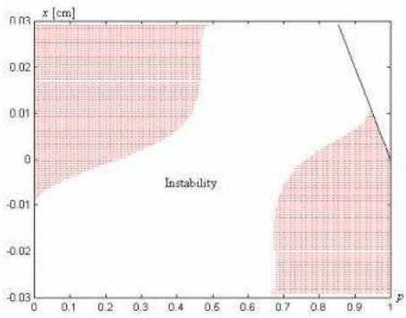
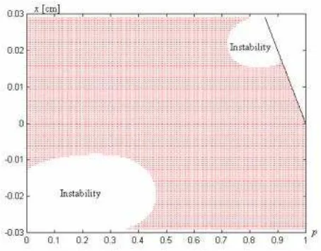
The relations (4.2)-(4.5) give the stability charts. Some of them are pre-sented in Figures 2, 3, 4, 5.
5. Concluding remarks
The conclusion of this paper, based on a thorough analysis of the Lya-punov stability of equilibria in a six-dimensional nonlinear model of a hy-draulic servomechanism, is that the elasticity of mounting structure induces a stabilizing structural feedback in the closed-loop system.
Figure 2: Full parameter space (p, x) stability of the system with nominal mass m= 30kg(E = 55×108
N/m, λ3 = 0.1)
Figure 3: Instability domain for increased mass, m = 60kg(E = 55 × 108
[image:8.612.176.403.385.563.2]Figure 4: Benefit of increased structural feedback, λ3 = 4/3 (the same pa-rameters as in Fig. 3, stability domain is easily increased)
Figure 5: Effect of increasing mounting structure elasticity - E decreased, E = 55×106
[image:9.612.177.404.386.564.2]The analysis performed in the paper took into account two quantities E (the larger isE the lower is the elasticity of the mounting structure) and λ3, essential for describing servoelastic properties and it was possible to evidence their contribution to stability of equilibria in Figures 2-5.
The model in the present paper is closer to reality than the one in [10] and has also the advantage to take into study internal, natural resources for stabilizing equilibria through adequate design of E and λ3.
References
[1] R. Taylor, R. W. Pratt and B. D. Caldwell, Effect of actuator nonlin-earities on aeroservoelasticity, Journal of Guidance, Control, and Dynamics, 19(2), (1996), pp. 309-315.
[2] A. Halanay, C. A. Safta, Stabilization of some nonlinear controlled electrohydraulic servosystems, Applied Mathematics Letters, 18(8), (2005), pp. 911-915.
[3] I. Ursu, M. Vladimirescu, F. Ursu, About aeroservoelasticity criteria for electrohydraulic servomechanisms synthesis, Proceedings of 20th Congress of the International Council of the Aeronautical Sciences, ICAS 96, Sorento, Italy, September 8-13, 2, (1996), pp. 2335-2344.
[4] I. Ursu, F. Ursu,Some absolute stability restrictions in output feedback synthesis of electrohydraulic servos, Proceedings of the International Confer-ence on Recent Advances in Aerospace Actuation Systems and Components, Toulouse, France, November 24-26, (2004), pp. 173-182.
[5] I. G. Malkin, Theory of Stability of Motion, Moscow, Nauka, (in Rus-sian), (English transl. Atomic Energy Comm, Translation, AEC-TR-3352), (1966), pp. 530.
[6] A. Halanay, C. A. Safta, F. Ursu, I. Ursu, Paper in preparation for publication.
[7] F. Kubica, T. Livet, Design of flight control system for an aeroelas-tic aircraft, Proceedings of the 3rd IEEE Control Applications Conference, Glasgow, (1994), pp. 335-340.
[8] Y. Ribakov, J. Gluck, A. M. Reinhorn, Active viscous damping sys-tem for control of MOOF structure, Earthquake engineering and structural mounting structures, 30, (2001), pp. 195-212.
Authors:
Ioan Ursu
”Elie Carafoli” National Institute for Aerospace Research Blvd. Iuliu Maniu 220, Bucharest 061126, ROMANIA email:[email protected]
Felicia Ursu
”Elie Carafoli” National Institute for Aerospace Research Blvd. Iuliu Maniu 220, Bucharest 061126, ROMANIA email:[email protected]
Andrei Halanay
Department of Mathematics 1, University Politehnica of Bucharest Splaiul Independent¸ei 313, Bucharest, 060042, ROMANIA
email:[email protected]
Carmen Anca Safta
Department of Hydraulic and Hydraulic Machinery, University Politehnica of Bucharest