Design of Semi-Automatic Soft Contact Lens Indexer
Inspection
Didi Istardi
Electric Machine and Control Laboratory Electrical Engineering Dept., Batam Polytechnis
Batam Indonesia [email protected]
Kemas Syaiful
Mechatronics Study Program
Electrical Engineering Dept., Batam Polytechnis Batam Indonesia
Abstract—Based on the consumer requirement for innovative products soft contact lens with international standards that can be useful to improve the quality of human life. Soft contact lens companies are always trying to develop methods of inspection their products to exceed the expectations of its customers. At this time has created a tool inspection manual as the tools to make sure the quality of the transparent product with the brands as ME5900 by microenterprise.inc it is based in the United States. With a simple design and requires a little bit maintenance. This tool works using Fiber Optic light source that penetrates the workpiece then projected against the surface of the screen. The author intends to develop such a device by re-design the semi-automatic inspection equipment by using the index system based rotary motor encoder. The show that the design improve efficiency of the machine, productivity and improve the quality of the inspection process of soft contact lens.
Keywords— soft contact lens, sistem index, motor rotary encoder
I. INTRODUCTION
The technology of process manufacture in industry has being improve and have trend to be autonomous especially in automotive and health care equipment’s. Based on this situation and the current requirement of soft contact lens product that must have innovative products with international standards, industry must improve the process of manufacturing from manual to automatic control. The manufacture process of soft contact lens that was be modified in the inspection of quality the soft contact lens. Currently, the process of inspection uses manual inspection that was using the transparent checker tool quality. This machine have a simple design and almost free maintenance. It works by using a fiber optic light source that penetrates the workpiece and then projected on the surface of 11.5 x 11.5 inch screen.
There are some soft contact lens inspection in the market such as from Optimec, Berkeley, JCC, and others. Due to current condition in the line production, this product was not match with other equipment. Based on some research in series elastic actuation (SEA) that be used as rigid actuation for process manufacturing [1-3]. The SEA can be used in robotic application that can also be implemented in process manufacturing. There are also some research in control of electric motor that was be used in this application [4-6]. The
type of electric motor that can be more efficient in this application was DC geared motor, DC servo motor, linear series motor, and AC motor. The control of system can be used PID controller as already done by some researchers [7-8].
According to that condition, in this paper the design of semi-automatic inspection system based on index using a rotary motor encoder was developed and implemented. By using this new inspection system, the productivity, efficiency and quality of product was improved. In this paper, the issues discussed are limited in the following areas: tool tray inspection did not change the dimensions of the devices that currently usage for the operator and the indexer machine are limited to inspected of the shape of lens surface on the screen sequentially and continuously as many as 48 pieces of contact lens of the each of its cycle.
The paper is organized as follows: In the next section, a brief review of rotary encoder, linear actuator and smartmotor are presented. In Section III, a description of the indexer for inspection contact lens design is given. Section IV and V presents results of simulation and analysis and discussion of the results. Finally, the conclusions are made in section VI.
II. INDEXER FOR INSPECTION CONTACT LENS SYSTEM
A. Rotary Encoder
Rotary Encoder is an electromechanical device that can monitor the movement and position of the actuator. Incremental encoder consists of a double track or single track and two sensor called channel A and B, while the phase relationship between channel A and B produce the direction of rotation. The resolution of the disc rotation can be measured by counting the number of pulses. Direction of rotation can be determined by knowing which the channel leading to others because both the channel will always be different quarter-turn phase (quadrature signal). Often there is a third channel output, called INDEX, which generates one pulse per revolution is useful for calculating the amount of rotation that occurs.
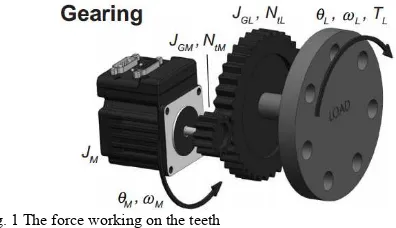
B. Gear
98% so that the gear is widely used to make the drive transmission to the shaft.
Fig. 1 The force working on the teeth
There are several factors that determine measures on gears can be show in Table 1 as follows:
TABLEI GEAR COMPONENT
No Component of Gear Results 1. Teeth number (z1) driver (estimated) 40 teeths 2. Teeth number (z2) driven (estimated) 200 teeths
3. Modul (M) 2
4. Contact angle (α) 45º
5. Teeth wide (b) 15.5 mm
6. Pitch diameter (DP) Dp = M . z 7. Outer diameter (Dk) Dk = Dp + 2. hk 8. Inner diameter (Df) Df = Dp – 2. hf 9. Teeth head high (hk) hk = 1 . M 10. Teeth feet high (hf) hf = 1,25 . M
11. Teeth high (H) H = hk + hf
12. Feet wide teeth (h) h = 0,45 . M .π 13. Tangensial force (FT) FT
14. Radial force (Fr) Fr = FT . tg α
15. Gear force ( FT .H = . b. h2.
16. Teeth press force ( =
17. Displacement teeth force ( =
C. Linear Lead Screw
Linear ball screw actuator is a mechanical equipment which uses the rotational motion of the moving objects with minimal friction. Screw on the shaft serves as groove ball bearing so that the removal can be done with precision / high-precision position that can be shown in Figure 2.
Fig. 2 Linear ball screw design
The Figure 2 shows that the linear ball screw was installed directly with Smartmotor with specific gear box. The design linear lead screw can be seen in Figure 3. The calculation for the soft contact lens inspection can be determined by (1)-(5).
(1) (2)
(3) (4) (5)
Fig. 3 Linear ball screw calculation
D. Smart Motor and PID Control
SmartMotor is a servo motor in which it is equipped by a servo control system. In a Smartmotor already include servo motor controller, amplifier and encoder. Things that are required to operate a Smartmotor is the power supply, internal programming and serial communication command from the outside (or both). The control of the motor use specific software that was dedicated for the motor.
it at rest, or part of an ongoing trajectory. This difference is called the position error.
The Proportional parameter of the PID control creates a simple spring constant. The further the shaft is rotated away from its target position, the more power is delivered to return it. With this as the only parameter, the motor shaft would respond just as the end of a spring would if it was grabbed and twisted.
If the spring is twisted and let go, it will vibrate wildly. This sort of vibration is hazardous to most mechanisms. In this scenario, a shock absorber is added to dampen the vibrations, which is the equivalent of what the Derivative parameter does. If a person sat on the fender of a car, it would dip down because of the additional weight based on the constant of the car’s spring. It would not be known if the shocks were good or bad. However, if someone jumped up and down on the bumper, it would quickly become apparent whether the shock absorbers were working or not. That’s because they are not activated by position but rather by speed. The Derivative parameter steals power away as a function of the rate of change of the overall PID control output. The parameter gets its name from the fact that the derivative of position is speed. Electronically stealing power based on the magnitude of the motor shaft’s vibration has the same effect as putting a shock absorber in the system, and the algorithm never goes bad.
Even with the two parameters working, a situation can arise that will cause the servo to leave its target created by “dead weight”. If a constant torque is applied to the end of the shaft, the shaft will comply until the deflection causes the Proportional parameter to rise with the equivalent torque. There is no speed so the Derivative parameter has no effect. As long as the torque is there, the motor’s shaft will be off of its intended target.
That’s where the Integral parameter comes in. The Integral parameter mounts an opposing force that is a function of time. As time passes and there is a deflection present, the Integral parameter will add a little force to bring it back on target with each PID cycle. There is also a separate parameter used to limit the Integral parameter’s scope of what it can do so as not to overreact.
III. SOFT CONTACT LENS INDEXER DESIGN
The design of the system was developed as Fig. 4. The smart motor as an actuator was controlled by computer using RS 232 cable data. Driver motor and rotary encoder, as a sensor, installed in smart motor block system.
Fig. 4 Soft contact lens indexer design
Mechanical design of the machine was designed to use two motors indexer. There were motor rotary axis (R-axis) and the linear motor (Y-Axis) as shown in Figure 6.
Fig. 6 Mechanical design
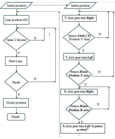
The design was based on the condition of the factory and the ergonomics aspect. The red line is area of contact lens and moveable equipment. The flow chart of the system can be seen in Figure 7.
Fig. 7 Flowchart the system
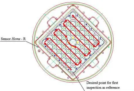
values of radial velocity on the wheel. The direction of the index rotary tables was determined by the values that was read by sensor as function of the speed motor. As for the order of the index on the inspection process can be described in the flowchart in Figure 7. As a protection of the system, there are a proximity sensor as a limit and home position. The system was run as follow red line in Figure 8.
Fig. 8 The movement of the inspection system
SmartMotor was moved at initial position to obtain maximum limits based on the edge of the sensor Limit -Y / Y + Limit and Home R – Y in beginning of the operation. The motor ran the scenario based on interface. The calculation of gear box would reference at Table I and the result shown at Table II.
TABLEII
GEAR COMPONENT CALCULATION
No Component of Gear Calculation I Calculation II
1. Teeth number (z1) driver
(estimated) 40 teeth 2. Teeth number (z2) driven
(estimated) 200 teeth
3. Module (M) 2 2
4. Contact angle (α) 45º 45º
5. Teeth wide (b) 15.5 mm 15.5 mm 6. Pitch diameter (DP) 80 mm 400 mm 7. Outer diameter (Dk) 320 mm 1600 mm 8. Inner diameter (Df) 315 mm 1595 mm 9. Teeth head high (hk) 2 mm 2mm 10. Teeth feet high (hf) 2.5 mm 2.5 mm
11. Teeth high (H) 4.5 mm 4.5 mm
12. Feet wide teeth (h) 2.83 mm 2.83 mm 13. Tangential force (FT) 14.125 N 2.825 N
14. Radial force (Fr) 12.06 N 2.41 N
15. Gear force ( 3.072 kg 0.6144 kg 16. Teeth press force ( 0.287 kg 0.054 kg 17. Displacement teeth force ( 0.322 kg 0.0644 kg
IV. RESULT AND DISCUSSION
The complete system of the contact lens inspection indexer was shown in Figure 9. There were two axis reference for the system. From the results of measurement and testing on the machine index obtained position data to the R-axis, Y-axis, the axis R + Y and positioning direction toward engine index. The measurement of movement indexer in R axis can be seen in Figure 10.
Fig. 9 Contact lens indexer inspection
Fig. 10 the movement of the indexer in R axis
In Y axis has a similar characteristic with R axis that shown in Fig. 11. The results of the test data showed that the Y axis error between the measured value and the actual value of below 1%. In Y axis more stable and precision compare to R axis.
Fig. 11 the movement of the indexer in Y axis
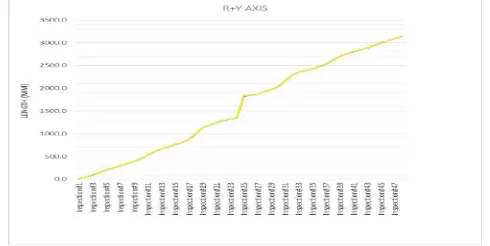
Table 3 is a table of motion testing machine index performed five times repeatedly from the first to the last inspection to the axis R + Y. From the results of the test data R + Y can be seen that the error between the measured value and the actual value of R + Y = 0:09%.
From the data in the field in getting the estimated time needed operator in checking the condition of the surface of the lens is less than about 5 seconds on each cycle. This has become one of the contributors to downtime on packaging machines that become the next process after the lens inspection process. So the total checking operator 5 seconds x 48 ea. = 240 seconds. While the engine indexer can carry out inspections for 2 seconds on each check lens 2 seconds x 48 ea. = 96 seconds.
Efficiency_on_the_indexer system are:
Efficiency_= (a manual inspection semi-automatic inspection time) / (manual_inspection_time)_x_100%
Efficiency = (240 seconds-96 seconds) / (240 seconds) x_100%
Efficiency = (144 seconds) / (240 seconds) x 100% Efficiency_=_60%
From the above calculations can take the conclusion that it is extremely improved its percentage of job efficiency and reduce machine downtime which in result by the length of waiting time the process of checking the condition of the lens surface by the operator.
Fig. 12Display inspection Formed in HMI
V. CONCLUSION
Based on the results and discussion of it can show as follows: Changes in methods of soft contact lens inspection process that was originally performed by manual processes first soft contact lens in use optispec 1 cycle, successfully developed into 48 soft contact lens inspected in one machine cycle using this indexer. By using this machine make it easy for the operator in the process of inspection of soft cotact lens. Soft contact lens inspection process more standard and easier control of the inspection process time.
Values in the position measurement accuracy approaching engine index data with the actual value of the average error value on R = 0.11%, Y = 0.08%, and an error value on R + Y = 0:09%. However this is not a significant problem because it does not require inspection tool precision inspection position. So the machine can be used in soft contact lens inspection_process.
REFERENCES
[1] N. Paine, Sehoon Oh, L. Sentis, “Design and control considerations for high performance series elastic actuators,” Mechatronics, IEEE/ASME Transactions on, vol 19. No.3, pp. 1080-1091, June 2014
[2] V. L. Orekhov, C. S. Knabe, M. A. Hopkins, D. W. Hong, “An unlumped model for linear series elastic actuators with ball screw drives,” Intellegents Robot and Systems (IROS) 2015 IEEE/RSJ
International Conference on, Hamburg German, pp. 2224-2230, Sept
2015.
[3] M. Hutter, C. D. Remy, M. A. Hoeflinger, and R. Siegwart, “Efficient and versatile locomotion with highly compliant legs,” Mechatronics, IEEE/ASME Transactions on, vol. 18, no. 2, pp. 449-458, 2013
[4] Hwi-Beom Shin, Jong-Gyu Park, “Anti-windup PID controller with integral state predictor for variable-speed motor drives,” IEEE Transaction on Industrial Electronics, vol. 53, No. 3, pp.1509-1516, March 2012
[5] T. Verstraten, R. Furnemont, G. Mathijssen, B. Vanderborght, and D. Lefeber, “Energy consumption of geared DC motors in dynamics aplication: comparing modeling approachers,” IEEE Robotics and Automation Letters, Vol.1, No. 1, pp. 524-530, January 2016
Transactions on Industrial Electronics, Vol. 61, No. 1, pp. 486-494, January 2014
[7] Q. Liu, J. Zhao, S. Schutz, and K. Berns, “ Adaptive motor patterns and reflexes for bipedal locomotion on rough terain,” Intellegents Robot and
Systems (IROS) 2015 IEEE/RSJ International Conference on, Hamburg
German, Sept 2015.