Effect of frequency and flexibility ratio on the seismic response of
deep tunnels
Eimar Sandoval
⇑, Antonio Bobet
Lyles School of Civil Engineering, Purdue University, West Lafayette 47906, United States School of Civil Engineering and Geomatics, Universidad del Valle, Cali, Colombia
Received 17 December 2016; received in revised form 6 April 2017; accepted 12 April 2017 Available online 1 June 2017
Abstract
Two-dimensional dynamic numerical analyses have been conducted, using FLAC 7.0, to evaluate the seismic response of under-ground structures located far from the seismic source, placed in either linear-elastic or nonlinear elastoplastic under-ground. The interaction between the ground and deep circular tunnels with a tied interface is considered. For the simulations, it is assumed that the liner remains in its elastic regime, and plane strain conditions apply to any cross section perpendicular to the tunnel axis. An elastoplastic constitutive model is implemented in FLAC to simulate the nonlinear ground. The effect of input frequency and relative stiffness between the liner and the ground, on the seismic response of tunnels, is evaluated. The response is studied in terms of distortions normalized with respect to those of the free field, and load demand (axial forces and bending moments) in the liner. In all cases, i.e. for linear-elastic and nonlinear ground models, the results show negligible effect of the input frequency on the distortions of the cross section, for input frequencies smal-ler than 5 Hz; that is for ratios between the wave length and the tunnel opening (k=D) larger than ten for linear-elastic and nine for non-linear ground. Larger normalized distortions are obtained for the nonnon-linear than for the non-linear-elastic ground, for the same relative stiffness, with differences increasing as the tunnel becomes more flexible, or when the amplitude of the dynamic input shear stress increases. It has been found that normalized distortions for the nonlinear ground do not follow a unique relationship, as it happens for the linear-elastic ground, but increase as the amplitude of the dynamic input increases. The loading in the liner decreases as the struc-ture becomes more flexible with respect to the ground, and is smaller for a tunnel placed in a stiffer nonlinear ground than in a softer nonlinear ground, for the same flexibility ratio.
Ó2017 Tongji University and Tongji University Press. Production and hosting by Elsevier B.V. on behalf of Owner. This is an open access article under the CC BY-NC-ND license (http://creativecommons.org/licenses/by-nc-nd/4.0/).
Keywords: Deep circular tunnel; Dynamic numerical analysis; Flexibility ratio; Distortion; Seismic response
1. Introduction
Underground structures must be able to support static overburden loads, as well as to accommodate additional deformations imposed by seismic motions. Progress has
been made in the last few years in understanding the soil-structure interaction mechanisms and the stress and dis-placement transfer from the ground to the structure during a seismic event. For most tunnels, with some exceptions including submerged tunnels, it seems well established that the most critical demand to the structure is caused by shear waves traveling perpendicular to the tunnel axis (Bobet, 2003; Hendron and Ferna´ndez, 1983; Merritt et al., 1985; Wang, 1993). Those waves cause distortions of the cross section (ovaling for a circular tunnel, and racking for a
http://dx.doi.org/10.1016/j.undsp.2017.04.003
2467-9674/Ó2017 Tongji University and Tongji University Press. Production and hosting by Elsevier B.V. on behalf of Owner. This is an open access article under the CC BY-NC-ND license (http://creativecommons.org/licenses/by-nc-nd/4.0/).
⇑ Corresponding author at: Lyles School of Civil Engineering, Purdue University, West Lafayette 47906, United States.
E-mail addresses: [email protected], [email protected](E. Sandoval),[email protected](A. Bobet).
Peer review under responsibility of Tongji University and Tongji University Press.
www.elsevier.com/locate/undsp
ScienceDirect
rectangular tunnel) that result in axial forces (thrusts) and bending moments.
Two approaches have been used to evaluate the seismic response of underground structures. One is the free field approach (Hendron and Ferna´ndez, 1983; Kuesel, 1969; Merritt et al., 1985; Newmark, 1967), which assumes that the structure follows the free field deformations of the ground, and therefore accommodates them without loss of its integrity. Authors supporting this approach have sug-gested computing deformations considering the perforated ground, given that most tunnels in competent ground would behave as perfectly flexible structures. This assump-tion however may result in extremely conservative designs, especially for stiff structures in a soft medium. The second approach is the soil-structure interaction approach (Bobet, 2003, 2010; Huo et al., 2006; Penzien, 2000; Wang, 1993). This approach, which is discussed in this paper, states that the underground structure modifies the free field deforma-tion of the ground around it such that demand and response depend on the relative stiffness between the ground and the tunnel support. Two dimensionless coeffi-cients have been proposed to consider soil-structure inter-action, namely the flexibility ratio and the compressibility ratio (Einstein and Schwartz, 1979; Peck et al., 1972). The flexibility ratio (F), or flexural stiffness, is a measure of the resistance of the system to change shape (i.e., distort) under a state of pure shear. The compressibility ratio (C), or extensional stiffness, is a measure of the all-around uni-form pressure required to cause diametric strain without change in shape. As the seismic shear waves distort the cross section of the tunnel, the flexibility ratio (F) is the main coefficient of interest in the evaluation of the seis-mic response of the cross-section of underground structures.
Analytical studies byPaul (1963), Mow and Pao (1971), Yoshihara (1963), Hendron and Ferna´ndez (1983), Merritt et al. (1985) showed that the dynamic amplification of stress waves impinging on a cavity is negligible when the wave length (k) of the seismic peak velocities is at least eight times larger than the width of the opening. This is usually the case for most structures located far from the seismic source. According to Dowding (1985) a far-field motion can be considered for distances from the seismic source between 10 and 100 km, with predominant frequen-cies between 0.1 and 10 Hz. With this assumption, pseudo-static numerical analyses have been carried out, and a num-ber of closed-form solutions have been proposed for seismically-induced motions (Bobet, 2003, 2010; Huo et al., 2006; Penzien, 2000; Wang, 1993). These solutions are based on elasticity (Timoshenko and Goodier, 1970), on early work byPeck et al. (1972), and on the relative stiff-ness method ofEinstein and Schwartz (1979).
The closed-form solutions are suitable for deep tunnels placed in an infinite, linear-elastic, homogeneous, and iso-tropic medium. A tunnel is considered deep if the stress gradient with depth has negligible or no effect on its behav-ior. A plane strain condition, which is reasonable for
sections located far from the face of the tunnel, is also assumed. The previous work has shown that the most important parameter determining the distortions of a cross section of a tunnel is the relative stiffness between the med-ium and the liner (expressed by the flexibility ratio,F), and that the depth and shape of the structure have second-order effects (Bobet, 2010). This conclusion however has been obtained considering linear-elastic ground. The more realistic seismic response of tunnels when considering the nonlinear stress-strain behavior of the ground under cyclic loading has not been evaluated.
The paper provides results of 2D plane strain dynamic numerical analyses, conducted in FLAC 7.0 (Itasca, 2011a), for deep circular underground structures subjected to vertically traveling shear waves, produced by a sinu-soidal input velocity. In the analyses, the liner is assumed elastic with a tied interface, i.e. no relative displacement between the structure and the ground. To evaluate the effect of the flexibility ratio on the seismic response without additional variables, the same interface is used in all the analyses. A tied interface is selected, as it includes a com-bined normal-shear stress transmission at the interface. The ground is considered dry (drained) i.e., no excess pore pressures are generated, with either linear-elastic or nonlin-ear elastoplastic response. In both cases, the effect of the input frequency on the distortions of the tunnel cross sec-tion is evaluated, as well as the effect of relative stiffness on the distortions of the liner. For the nonlinear ground, the loadings in the structure (thrusts and bending moments) are also obtained. Comparisons in terms of dis-tortions of the liner, for the linear-elastic and the nonlinear elastoplastic ground, are provided.
2. Linear elastic analysis
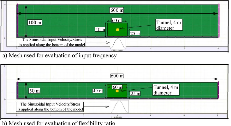
The ground-structure system is discretized in FLAC with meshes with dimensions 600 m wide and 100 m or 50 m high, to evaluate the effect of input frequency and the effect of flexibility ratio, respectively. The reasons to select these two different heights are explained later. For both meshes, square elements (1 m1 m) are used away from the tunnel, and square elements with a smaller size (0.5 m0.5 m), close to the tunnel, within a rectangular section of 60 m40 m. The center of the tunnel is located 25 m above the bottom of the model. Fig. 1 shows the meshes used for the dynamic numerical analyses.
A sinusoidal input velocity is imposed at the bottom of the discretization. Free-field boundaries on the sides and quiet boundaries at the bottom of the model are used. These are absorbing boundaries that use independent dash-pots in the normal and shear directions, to prevent reflec-tion of waves back into the model and avoid energy radiation (these boundaries are a built-in option in FLAC). By using absorbing boundaries, plane waves propagating upward do not distort at the lateral boundaries and do no reflect at the bottom boundary. (Itasca, 2011b; Lysmer and Kuhlemeyer, 1969).
The appropriate width of the model and good perfor-mance of the absorbing boundaries are verified by compar-ing shear strains at different points through the width of the mesh, for specific depths. Although not included here, the results show negligible differences at points located up to 80 m on each side of the center of the model. So the pro-posed discretization is considered adequate.
The tunnel support is modeled with elastic beam ele-ments. Beam elements are frequently used in this type of simulations because, similar to beams, liners must support axial forces and bending moments (e.g., Bobet, 2010; Wang, 1993).
2.1. Effect of input frequency on tunnel’s distortions
Previous research has found, when the ground’s response is elastic, that the dynamic amplification of stress waves impinging on a tunnel is negligible when the rise time of the pulse is larger than about two times the transit time of the pulse across the opening; that is, when the wave length (k) of peak velocities is at least eight times larger than the width (B) or diameter (D) of the opening (Hendron and Ferna´ndez, 1983; Mow and Pao, 1971; Merritt et al., 1985; Paul, 1963; Yoshihara, 1963). The fol-lowing numerical analysis is intended to evaluate the previ-ous finding and to use its results for comparison when the response of the ground is nonlinear.
Distortions for circular tunnels with 4.0 m in diameter and 0.40 m in thickness are obtained. The mesh has dimen-sions 600 m100 m. The depth of the model is selected to avoid the effect of waves reflection from the free surface, especially for input frequencies equal or lower than 1.0 Hz. According toItasca (2011b), the depth of the model
should be larger than one third to one fourth of the associ-ated wave length, to avoid this effect. The amplitude of the input velocity is 0.1 m/s, with frequencies ranging from 0.25 to 15 Hz. These frequencies correspond tok=Dratios ranging from 200 to 3.3, given the dimensions chosen for the tunnel. The wave length (k) is obtained as the ratio between the shear wave velocity in the medium (Cs) and
the frequency of the dynamic input (f).
The elastic properties of the medium, shear modulus (Gm) and Poisson’s ratio (mm), are assumed to be 80 MPa
and 0.25 respectively. For the liner, a value of 0.15 is used for the Poisson’s ratio (ms). A stiff tunnel with flexibility
ratio (F) equal to 0.125, and a flexible liner withF= 12.5 are used. The corresponding Young’s moduli for the liner’s material (Es) are 3.13105 and 3.13103MPa,
respec-tively. In this paper, the definition of flexibility ratio pro-vided by Peck et al. (1972), shown in Eq.(1), is used.
F ¼ Em=ð1þmmÞ
6EsIs=ðR3ð1 m2sÞÞ
ð1Þ
whereEmis the Young’s modulus of the medium,Isis the
moment of inertia of the liner per unit length, andRis the radius of the tunnel.
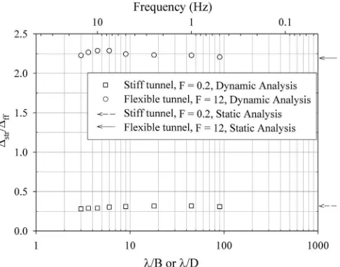
Fig. 2shows the results of both relative stiffnesses, when the wave length or input frequency is changed. The inset in the figure shows a schematic of the ovaling distortions for a circular support. The figure plots the maximum distortions, which occur at maximum amplitude of the sinusoidal input velocity, normalized with respect to the ground distortions in the free-field, i.e. distortions of the ground without the liner. The normalized distortions are expressed as a func-tion of the ratiok=D(bottom horizontal axis). For
ison purposes, the top horizontal axis presents the values of the input frequency (f).
Fig. 2 shows that the more flexible liner (F= 12.5) has larger normalized distortions than the stiffer liner (F= 0.125). This behavior is expected as the flexible struc-ture deforms more than the stiff strucstruc-ture and also more than the soil it replaces. Small differences in response are observed with the input frequency, depending on the flexi-bility ratio. For the stiff structure (F= 0.125), the normal-ized distortions are almost constant for k=Dratios larger than ten (f< 5.0 Hz). For lower k=D ratios (higher f), a small reduction in the normalized distortions is observed. For the flexible structure on the other hand, negligible dif-ferences in the normalized distortions are observed fork=D
ratios larger than ten (f< 5.0 Hz). Afterwards, the normal-ized distortions increase up to a point, and then decreases as the k=Dratios decrease (fincreases). Overall, the effect of frequency is negligible for k=D ratios larger than ten, i.e., for input frequencies (f) lower than 5.0 Hz.
These results, obtained through fully dynamic numerical analyses, confirm the assumption made for analytical solu-tions that a pseudo-static analysis is sufficient when the ratio between the wave length and the opening of the liner is larger than eight (ten in this paper), if a linear-elastic medium is considered.
2.2. Effect of relative stiffness on tunnel’s distortions
Previous work, based on analytical solutions and numerical analyses, has found that the main parameter controlling the distortions of the cross section of the liner is the relative stiffness between the structure and the ground (e.g.,Bobet, 2010; Penzien, 2000; Wang, 1993). To extend the database available for linear-elastic ground, and to have results that can be compared with those of the nonlin-ear ground in Section3, dynamic numerical analyses for a
sinusoidal input velocity with 0.1 m/s of amplitude and 2.5 Hz of frequency are performed. Note that, in the pre-ceding section, it was shown that at this frequency the results are frequency-independent. The applied input veloc-ity corresponds to an input shear stress equal to 40 kPa.
For the input frequency used (2.5 Hz), the depth of the model can be taken as 50 m, since no unwanted reflections from the surface are produced. This decreases the compu-tation time of the simulations. Consequently, the effect of the relative stiffness, for the linear-elastic ground and for the nonlinear ground, is evaluated for a mesh 600 m50 m. In this section, the same tunnel geometry and elastic properties of the ground considered in the pre-ceding section are used.
Fig. 3shows the normalized maximum distortions, for flexibility ratios ðFÞranging from 0.125 (a relatively very stiff tunnel) to 15 (a relatively very flexible tunnel). It can be seen inFig. 3 that the normalized distortions increase as the flexibility ratio increases. As stated in Section 2.1, this trend is anticipated because asFincreases, the tunnel becomes much more flexible than the soil it replaces. For an elastic analysis, the magnitude of the dynamic input should not affect the results, due to the normalization.
Fig. 3 corroborates this assumption by including results for three different flexibility ratios (F= 0.25, 1 and 12.5) with dynamic input that changes by a factor of 3.
The flexibility ratio used in this paper, and proposed by
Peck et al. (1972), provides a good measure of the stiffness of the structure relative to the ground. A value of F ¼1 represents a structure with stiffness equal to that of the ground that it replaces, and so the distortions of the struc-ture are those of the free field (normalized distortions equal to 1.0). A valueF >1 represents a structure more flexible than the ground, and the distortions of the structure are larger than those of the free field. A valueF <1 represents a structure stiffer than the ground, and the distortions are smaller than those in the free field.
Fig. 2. Effect of input frequency on distortions of circular tunnels placed in linear-elastic medium.
Fig. 3. Normalized distortions for circular tunnels placed in linear-elastic medium.
3. Nonlinear elastoplastic analysis
Soils and other geomaterials usually behave as elastic only at very small strains. In general, those materials show a nonlinear stress–strain behavior with strain, with a reduc-tion of stiffness with increased strains. As a result, higher strains in the free field are anticipated for nonlinear ground, compared to a linear-elastic ground. Conse-quently, given that the response of a tunnel under seismic loading is a soil-structure interaction problem, differences in the seismic response are expected.
It must be noted that due to the stiffness degradation of the ground, the flexibility ratio changes during the dynamic loading. More precisely, if the liner remains in its elastic regime F decreases, as the ground becomes more flexible with deformation, i.e., the tunnel becomes stiffer with respect to the ground as the ground deforms. The flexibility ratios reported here are those computed using the degraded stiffness of the medium at peak distortions of the tunnel. The free field shear strains used for the normalization cor-respond to those of the degraded ground.
As with the elastic ground case, the effect of the input frequency and the effect of the flexibility ratio on the distor-tions of the cross section are investigated. The effect of flex-ibility ratio on loadings of the liner is also evaluated. The distortions obtained are then compared to those found for a linear-elastic medium. A constitutive model to repre-sent the nonlinear elastoplastic ground is prerepre-sented and implemented in FLAC.
3.1. Cyclic nonlinear elastoplastic model
The elastoplastic model proposed is based on that devel-oped by Jung (2009) and modified by Khasawneh et al. (2017), and is intended to simulate the nonlinear behavior observed in geological materials, even for small shear strains around 10 5 (Dobry et al., 1981; Vucetic, 1994). The nonlinear behavior is simulated with a modified hyper-bolic relationship. Jung (2009) proposed to obtain the degraded shear stiffness of the ground (G) by means of Eq. (2), as a function of the modified hyperbolic strain (ch) proposed by Hardin and Drnevich (1972), which is
given in Eq.(3).
shear stress at failure, Go is the shear modulus at small
strains, cis the current shear strain, anda andb are soil constants that determine the deviation of the stress–strain relation from the hyperbolic function.
The model also includes the dependence of stiffness on confinement. Jung (2009) proposed Eq. (4) to calculate the change in the shear modulus for small strains (dGo),
as a function of the change in the effective confinement (dr0
mðrefÞis the reference effective mean stress (for
geo-static conditions), andGoðrefÞis the corresponding reference
small strain shear modulus.
The hysteretic behavior during cyclic loading is based on
Pyke (1979), who proposed a modification to the Masing’s rules.Jung (2009)provided Eq.(5)to calculate the stiffness reduction in the hysteresis loop in the three dimensional space. Eq. (6) is an extension hyperbolic strain (Eq. (3)) in 3D and is based on the octahedral shear strain (coct),
defined in Eq.(8). This modification is required as the orig-inal hyperbolic strain proposed by Hardin and Drnevich (1972)was obtained from 1D cyclic simple shear tests.
G¼Go
wherenis a scaling factor for the hysteresis loop (n= 2 to satisfy Masing rules or n–2 for non-symmetric cyclic
loading),coct;r is a reference octahedral shear strain,coct;rev
is the octahedral shear strain at reversal,eijis the deviatoric
strain tensor,ij is the Lagrangian strain tensor, anduiare
the displacements along thexiaxis.
Small strain analysis is assumed, and thus the strain increment (dij) is decomposed into its elastic and plastic
components dij¼deijþd p ij
, with the stress increment computed from Eq.(11).
drkl¼Ceklijd e
ij ð11Þ
wheredrklis the incremental stress tensor,Cklijis the elastic
modulus tensor, and dij is the incremental elastic strain
tensor.
After yielding, which is defined with the Drucker-Prager (D-P) criterion, the plastic strains are determined by means of a strain hardening law with a non-associated flow rule. Eqs. (12) and (13)show the yield function and the plastic potential, respectively. More details about the cyclic elasto-plastic model, including the complete formulation, imple-mentation and its verification can be found in
f ¼ ffiffiffiffiffiffiffi3J2 p
þ13I1tanðaÞ j ð12Þ
g¼ ffiffiffiffiffi
J2
p 1
3I1tanðuÞ ð13Þ whereJ2= 1/2(SijSij) is the second invariant of the
devia-toric stress tensor,I1¼rkkis the first invariant of the stress
tensor,a is the D-P friction angle,j is the D-P cohesion, anduis the dilation angle.
3.2. Effect of input frequency on tunnel’s distortions
A mesh 600 m100 m with a circular tunnel placed 25 m above the bottom is used. The liner, assumed to remain in its elastic regime, has again 4 m in diameter and 0.4 m in thickness.
A ground with initial stiffness GoðrefÞ¼80 MPa, and
Poisson’s ratiomm¼0:25 is used in the simulations. Similar
to the linear-elastic ground, a stiff and a flexible liner are considered. The Poisson’s ratio for the liner’s material is assumed ms¼0:15, and the Young’s moduli (Es) are
1.56105and 2.61103MPa, for the stiff and the flexible structure, respectively. Such stiffnesses represent initial flex-ibility ratios (F) of 0.25 and 15 that are reduced during the dynamic phase to values of 0.20 and 12.0, respectively (at peak distortions). The input frequencies range from 0.50 to 15 Hz, which correspond to k=D ratios (considering the degraded ground) ranging from 90 to 3, given the dimensions chosen for the tunnels. In the results, displayed inFig. 4, it can be seen that negligible changes in the distor-tions of the liner are observed for k=Dratios larger than nine (f <5 Hz), for both the flexible and the stiff structure. Similar to the linear-elastic ground, fork=Dratios smaller than nine, a reduction in the normalized distortions is observed in stiff liners. For flexible liners, an increase of distortions with a later decrease is detected.
For completeness, static numerical analyses for both the flexible and the stiff tunnel are performed. A square model 50 m50 m with the tunnel located at the center (25 m from the bottom, as in the dynamic case) is used. In the analyses, inertial forces are neglected and a simple shear condition producing the same free field shear strain than the free field induced by the dynamic loading is used. The results are included as arrows on the right vertical axis of
Fig. 4. Negligible differences are observed in normalized distortions obtained from the static analyses, or from dynamic analyses for k=D ratios larger than nine (f <5 Hz). Consequently, for nonlinear ground, a pseudo-static analysis is feasible for ratios between the wave length and the tunnel opening larger than nine.
3.3. Effect of relative stiffness on tunnel’s distortions
As before, a mesh 600 m50 m is used to assess the effect of the relative stiffness on the tunnel response. The tunnel is again placed 25 m above the bottom of the model, and has 4 m in diameter and 0.40 m in thickness.
A parametric study for three different stiffnesses of the ground (GoðrefÞ= 40, 80, and 200 MPa) is performed. These
values represent medium stiff soil, very stiff soil, and weak rock, respectively. An input velocity with 2.5 Hz frequency is used. This frequency is selected, based on the results obtained (shown inFig. 4), to have the distortions indepen-dent of frequency. Given that the magnitude of the shear stress induced by a dynamic input velocity or acceleration is directly related to the stiffness of the ground, the ampli-tude of the input velocity is selected such that the same input shear stress (s) at the bottom of the discretization is obtained for the three stiffnesses of the ground investigated. A shear stress with magnitude 40 kPa is applied, which cor-responds to input velocities of 0.14, 0.10 and 0.06 m/s, for
GoðrefÞ 40, 80 and 200 MPa, respectively. These velocities
are representative of strong to very strong earthquakes, with magnitudes between VI and VII in the Modified
Mer-Fig. 4. Effect of input frequency on distortions of tunnels placed in nonlinear ground.
Fig. 5. Normalized distortions for circular tunnels placed in nonlinear ground, for the same input shear stress amplitude and for different initial ground stiffness.
calli Intensity Scale, according to the classification pro-vided by Wald et al. (1999). The initial flexibility ratios (F) range from 0.10 to 15, which result in final flexibility ratios (F) ranging between 0.08 and 12, due to the stiffness reduction in the ground with deformation.
The results of the simulations are shown inFig. 5. For comparison purposes, the plot also includes results using a linear-elastic medium that has the same stiffness as that of the degraded ground of the nonlinear analyses. It can be seen in the figure that, for the same flexibility ratio, higher normalized distortions occur with the nonlinear ground, with differences increasing as the tunnel becomes more flexible. This behavior is expected, as the nonlinear ground surrounding the structure degrades, and so there is a higher strain demand on the structure. For the nonlin-ear ground, it can also be seen that normalized distortions are almost the same when the same input shear stress is used, irrespective of the initial stiffness of the ground.
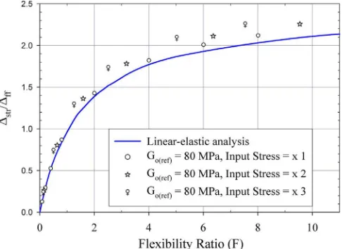
To verify whether the relationship between distortions and flexibility ratio for a nonlinear ground can be expressed by means of a single curve, as it is done for a linear-elastic ground (see Fig. 3), analyses are performed for different amplitudes of the input shear stress. The amplitude of the input shear stress used in Fig. 5 is increased by a factor of two and three, while the other parameters are kept constant.Fig. 6compares the normal-ized distortions for GoðrefÞ= 80 MPa for the three cases.
Important differences in the normalized distortions are observed when the amplitude of the input stress is changed, for the same final (degraded) flexibility ratio. It can also be seen inFig. 6that the differences with respect to the linear-elastic case increase as the amplitude of the dynamic input increases. Hence, there is not a unique relationship between the flexibility ratio and the normalized distortions when a nonlinear ground is assumed, in contrast to what happens with a linear-elastic ground where the relationship is unique. Indeed, the nonlinear ground, under a higher input stress, will deform more than under a lower input stress,
and so its stiffness will be smaller, which will result in larger deformation demands to the structure.
3.4. Effect of relative stiffness on liner’s loading
The effect of the flexibility ratio on the thrusts and bend-ing moments of the liner for a nonlinear ground is evalu-ated, by considering two different stiffnesses of the ground, namelyG0ðrefÞ= 80 and 200 MPa.
Figs. 7 and 8 show the results for thrusts and bending moments, respectively. In the figures, the thrusts are nor-malized by the product of the input shear stress and the radius of the tunnel (sR); and the bending moments are normalized by the product of the input shear stress and the square of the radius of the tunnel (sR2), as proposed byEinstein and Schwartz (1979).
It can be seen in the figures that larger thrust and bend-ing moments occur for stiffer structures, i.e., for lower flex-ibility ratios (F), which decrease as the tunnel becomes
Fig. 6. Normalized distortions for circular tunnels placed in nonlinear ground, for different input shear stress amplitude and for the same initial ground stiffness.
Fig. 7. Normalized axial forces (thrusts) for circular tunnels placed in nonlinear ground.
more flexible (as F increases). In fact, almost negligible bending moments are obtained for flexibility ratios larger than 10, as the structure approaches a perfectly flexible tun-nel (Peck et al., 1972) that cannot withstand bending moments. These results support the statements made by previous authors (e.g., Kuesel, 1969; Monsees & Merritt, 1991) in that increasing the stiffness of the structure is not the best solution for seismic design, as stiffer structures will take greater loads. For the seismic design, these authors suggested increasing the ductility of the liner to absorb the imposed seismic distortions, rather than increas-ing the stiffness or strength of the liner. It can also be seen in Figs. 7 and 8that for the same flexibility ratio, smaller thrust and bending moments are observed for the stiffer nonlinear ground than for the softer nonlinear ground, as the first deforms less.
4. Summary and conclusions
The paper evaluates the dynamic response of deep circu-lar tunnels placed in linear-elastic and nonlinear elastoplas-tic ground. Dynamic numerical analyses using FLAC 7.0 are performed. For the elastoplastic ground, a constitutive model based on hyperbolic behavior is implemented in FLAC. The effect of the input frequency on the distortions of the cross section and the effect of the flexibility ratio on the distortions of the liner are evaluated for linear-elastic and nonlinear ground. For nonlinear ground, the effect of the flexibility ratio on the loadings of the liner is also inves-tigated. Plane strain conditions and deep tunnel with a tied interface are assumed.
The results show that for both linear-elastic and nonlin-ear elastoplastic ground, there is no effect of the input fre-quency on the seismic response of the tunnel, when the input frequency is smaller than 5 Hz (k=Dratios larger than ten for linear-elastic and nine for nonlinear ground). Pseudo-static analyses can therefore be conducted for tun-nels located far from the seismic source (for distances between 10 and 100 km from the epicenter, after
Dowding, 1985), irrespective of the soil model used in the simulations.
As it has been found in previous work with the assump-tion of linear-elastic ground (e.g., Bobet, 2010; Wang, 1993), normalized distortions (tunnel distortions normal-ized by those of the ground far from the tunnel) increase as the tunnel becomes more flexible with respect to the ground i.e., when the flexibility ratio (F) increases. A unique relationship between the flexibility ratio and the normalized distortions of the tunnel is found for linear-elastic ground, irrespective of the amplitude of the dynamic input. Similarly, for nonlinear ground, normalized distor-tions increase when the flexibility ratio increases. The nor-malized distortions are higher than those considering a linear-elastic medium with the same flexibility ratio; the dif-ferences increase as the tunnel becomes more flexible (asF
increases), and when the amplitude of the shear stress
imposed by the dynamic input increases. It must be noted that, different to the linear-elastic medium, there is not a unique relationship between the flexibility ratio and the normalized distortions for nonlinear ground, as those increase with the amplitude of the dynamic input, for the same relative stiffness.
Higher axial forces and bending moments are observed for stiffer structures (lower flexibility ratios) irrespective of the ground model used. The loading of the liner decreases as the tunnel becomes more flexible than the ground (as the flexibility ratio increases). This finding is informative, since providing ductility to the support to absorb the deformations imposed by the earthquake may be more effective than increasing its stiffness.
The results of the dynamic numerical analyses con-ducted provide clear support to the importance of the role that the relative stiffness between the ground and the liner has on the seismic response of underground structures. The implication of this observation is significant: the free field approach should be abandoned for design.
Acknowledgments
The financial support of the Colombia-Purdue Institute for Advanced Scientific Research (CPI), Universidad del Valle (Colombia) and Purdue University – United States is gratefully acknowledged.
References
Bobet, A. (2003). Effect of pore water pressure on tunnel support during static and seismic loading.Tunnelling and Underground Space Tech-nology, 18(4), 377–393. http://dx.doi.org/10.1016/S0886-7798(03) 00008-7.
Bobet, A. (2010). Drained and undrained response of deep tunnels subjected to far-field shear loading.Tunnelling and Underground Space Technology, 25(1), 21–31.http://dx.doi.org/10.1016/j.tust.2009.08.001. Dobry, R., Yokel, F. Y., & Ladd, R. S. (1981). Liquefaction potential of overconsolidated sands in moderately seismic areas. In Earthquakes and earthquake engineering in the Eastern U.S.(Vol. 2, pp. 643–664). Knoxville, Tenn.
Dowding, C. (1985). Earthquake response of caverns: Empirical correla-tions and numerical modeling.Proc. rapid excavation and tunneling conference, New York, New York(Vol. 1, pp. 71–83)..
Einstein, H. H., & Schwartz, C. W. (1979). Simplified analysis for tunnel supports. Journal of the Geotechnical Engineering Division, 105, 499–518.
Hardin, B. O., & Drnevich, V. P. (1972). Shear modulus and damping in soils: Design equations and curves.Journal of the Soil Mechanics and Foundations Division, 98(7), 667–692.
Hendron, A. J., Jr., & Ferna´ndez, G. (1983). Dynamic and static design considerations for underground chambers. In Seismic Design of Embankments and Caverns, ASCE Symposium, Philadelphia, Pennsyl-vania(pp. 157–197).
Huo, H., Bobet, A., Ferna´ndez, G., & Ramı´rez, J. (2006). Analytical solution for deep rectangular structures subjected to far-field shear stresses. Tunnelling and Underground Space Technology, 21(6), 613–625.http://dx.doi.org/10.1016/j.tust.2005.12.135.
Itasca (2011a).FLAC fast Lagrangian analysis of continua, ver. 8.0(5th ed.). Minneapolis, MN: Itasca Consulting Group.
Itasca (2011b). FLAC fast Lagrangian analysis of continua, ver. 8.0, dynamic analysis (5th ed.). Minneapolis, MN: Itasca Consulting Group.
Jung, C. M. (2009). Seismic loading on earth retaining structures PhD thesis. Purdue University.
Khasawneh, Y., Bobet, A., & Frosch, R. (2017). A simple soil model for low frequency cyclic loading.Computers and Geotechnics, 84, 225–237. http://dx.doi.org/10.1016/j.compgeo.2016.12.003.
Kuesel, T. R. (1969). Earthquake design criteria for subways.Journal of the Structural Division, 6, 1213–1231.
Lysmer, J., & Kuhlemeyer, R. L. (1969). Finite dynamic model for infinite media. Journal of the Engineering Mechanics Division ASCE, 95, 859–877.
Merritt, J. L., Monsees, J. E., & Hendron, A.J., Jr. (1985). Seismic design of underground structures. In Proc. rapid excavation and tunneling conference(Vol. 1, pp. 104–131). New York, New York.
Monsees, J. E., & Merritt, J. L. (1991). Earthquake considerations in design of the Los Angeles metro. In Proc. third US conference on lifeline earthquake engineering(pp. 75–88). California: Los Angeles. Mow, C. -C. & Pao, Y. -H. (1971). The diffraction of elastic waves and
dynamic stress concentrations. Technical report, R-482-PR, United States Air Force Project Rand.
Newmark, N. M. (1967). Problems in wave propagation in soil and rock. In Proc. international symposium on wave propagation and dynamic properties of earth materials, Albuquerque, Mexico(pp. 7–26). Paul, S. L. (1963).Interaction of plane elastic waves with a cylindrical cavity
PhD thesis. University of Illinois.
Peck, R. B., Hendron, A. J., & Mohraz, B. (1972). State of the art of soft-ground tunneling. Proc. rapid excavation and tunneling conference, Chicago, Illinois(Vol. 1, pp. 259–286)..
Penzien, J. (2000). Seismically induced racking of tunnel linings. Earth-quake Engineering and Structural Dynamics, 29(5), 683–691.http://dx.
doi.org/10.1002/(SICI)1096-9845(200005)29:5<683::AID-EQE932>3.0.CO;2-1.
Pyke, R. (1979). Non linear soil models for irregular cyclic loadings.
Journal of the Geotechnical Engineering Division, 105(GT6), 715–726. Timoshenko, S., & Goodier, J. (1970). Theory of elasticity (3rd ed.).
McGraw-Hill.
Vucetic, M. (1994). Cyclic threshold shear strains in soils. Journal of Geotechnical Engineering, 120(12), 2208–2228.
Wald, D. J., Quitoriano, V., Heaton, T. H., & Kanamori, H. (1999). Relationships between peak ground acceleration, peak ground veloc-ity, and modified Mercalli intensity in California.Earthquake Spectra, 15(3), 557–564.http://dx.doi.org/10.1193/1.1586058.
Wang, J. -N. (1993). Seismic design of tunnels. A simple state-of-the-art approach. Technical report, Parsons Brinckerhoff Monograph 7. Yoshihara, T. (1963). Interaction of plane elastic waves with an elastic