Simulation Model of Wind Turbine with Induction Generator
Lie Jasa1,2
Electrical Engineering Department 1
Udayana University Bali, Indonesia
2Sepuluh Nopember Institute of Technology Surabaya, Indonesia
1
[email protected], [email protected]
Mochamad Ashari1, Ardyono Priyadi2, Mauridhi Hery Purnomo3
Electrical Engineering Department Sepuluh Nopember Institute of Technology
Surabaya, Indonesia 1
[email protected], [email protected], 3
Abstract—Conventional energy sources used these days comes from the limited energy resources that will be exhausted in the near future. Research on wind energy as one of the renewable energy sources has been promoted by researchers in many countries around the world. Wind energy approach is a potential resource of energy and environmentally friendly. However, the main constraint in studying it is the wind cannot be regulated because it changes in speed at all times in accordance with the wind guts. The present study aimed to determine the characteristics of wind turbine that were connected with induction generator by applying simulation technique using Matlab. The results showed that by using the maximum wind speed of 12 m/s with the pitch angle β = 0 degree, the mechanical output power (Pm) is 25513942.39 watt. When the pitch angle β was increased up to 11o with the maximum wind speed, the Pm
dropped to 10168366.36 Watt. Moreover, the induction generator output current of I2C with the maximum wind speed and at λ value of 8 is the maximum current produced by the generator. The computing processes and outputs, and the stages of wind energy installation are discussed in details.
Keywords – Wind turbine, Renewable, Wind energy, blade.
I. INTRODUCTION
The energy crisis faced by all countries in the world nowadays is due to the limitations of conventional energy sources such as oils, coal and gases that have been used.The excessive energy use over the years gives impact on air pollution, global warming and climate change. Almost all countries in the world today are competing to conduct research on wind energy that is used as one of the policy option in the future energy development. Besides, it is an environmentally friendly, green, unlimited and renewable energy sources, the wind energy is less cost competitive. This was proven when the installation of wind turbines in parts of the world increased by 30% and wind turbine generator industries like in china have more than 80 producers [1], [2], [3], [4], [5].
The main problem faced by researchers in the world today is the nature of the wind always changes and the speed can not be regulated. Consequently, the sustainalibility of wind energy resources is still not able to compensate for conventional energy generation. The wind energy therefore should be
developed in various studies and experiments [1], [6], [11]. On this paper, the simulation of Matlab showed a wind turbine connected to an induction generator with characteristics of wind speed (V-wind), Pitch lade (β), blade speed ratio (λ), performace coefisien turbine (Cp), mechanical power output (Pm), the current output (I2C), and power generator output (Pw).
II. PLANTS MODEL
A. Wind Turbine.
Wind turbine is a turbine that is used to convert kinatic energy of wind into electrical energy. Theorerically, the stronger the wind blows, the greater the mechanical energy was generated [12, 13, 14]. When the mechanical energy is connected to an induction generator, the rotation of wind turbine rotor will move from induction machine and will produce an output voltage in the stator known as electrical energy. Wind turbine is originally created to meet the needs of farmers in making rice mills, agricultural irrigation purposes and etc. Many wind turbines that are known to many people over the years are built in Denmark, the Netherlands and other European countries called as the windmill [12, 13].
There are two types of wind turbines [13,14,15]. (1) Propeller wind turbine with horizontal axis. This wind turbines should be directed in accordance with the highest wind direction speed, and (2) Darrieus wind turbine is a type of vertical axis wind turbine discovered by GJM Darrieus in 1920. The advantage of this type of wind turbine is around the turbine does not require mechanisms on wind direction [14].
The main supporting components of a wind turbine that can generate electrical energy, are as follows [14]. (a) Gearbox: serves to change the low round on the mill into high rotation; (b) Brake System: is used to keep the rotation on the shaft after the gearbox in order to work safely at the point when a large wind speeds, to avoid overheating, breakdown rotor, wires at the generator end; (c) Generator: is used to convert the kinetic energy into electrical energy; (d) Energy storage: serves as back-up electrical energy when the load increases or the use of electrical power when the wind speed of a region is diminishing; (e) Rectifier-inverter: rectifier can rectify sinusoid wave (AC) produced by the generator into a wave DC while Inverter has the opposite function; (f) Sensors: wind turbines can be used to direct the wheel position (blade) in the direction of the wind, so the windmill rotates though the wind is always changing; and the last (g) Wind turbine safety system: is a lightning rod that serves as a protection from lightning strikes
The formula of the power of wind turbine input is given by [12]:
Pm = 1/2 ρAV3wind (1)
where Pm is the power generated by wind, ρ (Rho) is the air density (kg/m3) and is of 1255 kg/m3, A is the area of a circle in the wind turbine blade (m2), and Vwind is wind speed in m/s.
While the equation for the wind turbine output [12] is that a model of wind turbine connected to an induction generator is theoretically generate output equation as shown in equation (2):
Pm = Cp(λ,β) 1/2 ρ A V3wind (2)
C
)e
C
-C
-C
(
C
=
)
,
Cp(
6 -C5 4 2 i 2 1 i
(3)where Pm is the mechanical power output of the turbine, Cp is the performance coefficient of the turbine, λ is the ratio of the speed of the rotor blade to the wind velocity, and β is the blade pitch angle (degrees). Coefficients C, then respectively are C1 = 0.5176, C2 = 116, C3 = 0.4, C4 = 5, C5 = 21, and C6 = 0.0068 [12]. Cp-λ characteristics, for the pitch angle β, is assumed to be lower. The maximum value of Cp is 0:48 (CPmax = 0.48), for β = 0 ° and for λ = 8.1.
By connecting between λ and β, and λi –next values of λ- lamda values will change and keep changing in every moment. The equation is expressed by:
1
035
.
0
08
.
0
1
1
3
i (4)B. Generator Induksi. Induction generator
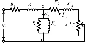
The working principle of the equivalent circuit is to use electromagnetic induction [15]. Primary and secondary sections can be described by an equivalent circuit as shown in Figure 1. I ) 1 ( '2 S S R 2 ' R 2 ' X 1
R X1
c
R Xm
2
'
I
Figure 1.Equivalent circuit of induction generator
By using Thevenin's theorem, the voltage at point X and Y generates equation V1 = Vt - Io (R1 + jX1), so a substitute circuit can be illustrated as Figure 4.
I ) 1 ( '2 S S R 2 ' R 2 ' X 1
R X1
c
R Xm
2
'
I
Figure 2. Substitute circuit of induction generator
2 2 1 2 2 1
1 2
) ' (
)
( X X
S R R
V I
c c
(5)
The output power of induction generator is a square of output current with I2C on the load resistance value R2C, so the power out equation becomes equation 6.
)
1
(
)
(
3
22 2
S
S
R
I
Pm
c c
(6)Based on the major and supporting components of wind turbine, and the formula 1 to 6 discussed above, the present researchers proposed a model wind turbine with induction generator as shown in Figure 3.
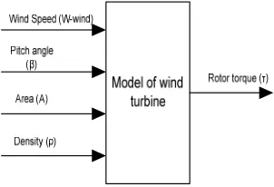
Figure 3. Model of wind turbine with induction generator control
Wind turbine model in Figure 3 uses the parameters of wind speed (V-wind) that always changes; pitch angle (β) is the blade angle that can be changed to compensate for wind speed; turbine swept area (A) is the area while it rotates blade area , and the wind density (ρ). All the parameters are used as input to obtain the turbine mechanical power (Pm) as shown in Figure 4.
Figure 4. Parameter input of wind turbine model
Maximum mechanical power turbine will be simulated using Matlab software.
III. METHODOLOGY
To compute a simulation using Matlab, this study proposed the stages for calculating the maximum mechanical power output of wind turbine, as follows:
1. Analyzing the process of wind turbines, V-wind, pitch angle (β), the turbine swept area (A), and the wind density (ρ). The wind turbine work is based on wind speed to be converted into mechanical energy.
2. Breakdown the wind turbine with the radius of turbine, which is wind density (rho) = 1225 kg/m3, and the area A = 12.5663 which the radius is assumed 2 meters, the value of the equation (4) parameter of C1 = 0.5176; C2 = 116; C3 = 0.4; C4 = 5; C5 = 21; C6 = 0.0068
3. Analyzing the output of equation (2), (3) and (4) to obtain the value of mechanical power output (Pm) of the turbine, then Pm will be entered into the equation (5) of the equation of induction generator.
4. Having inserted the value of Pm, then the value I2C can be calculated by the equation (5). Having the value I2C, the output power then can be calculated by the formula Pout = (I2C) 2 R2C in equation 6.
IV. SIMULATION RESULTS
Simulation model of wind turbines in this study uses Matlab R2009b. Performance coefficient (Cp) was computed by the value of λ from 0 to 15 and the value of β from 0 to 20 as in Figure 4. Cp with a value of β 0.5, 10, and 15 is shown separately in Figure 5.
Figure 4. Characteristic of wind turbine λ vs Cp β ranging 0-20
Figure 5. Characteristic of wind turbine λ vs Cp
(■-β=0 ▲-β=5 ∆- β=10 ○- β=15)
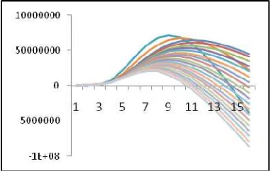
In order to obtain the mechanical power output, Pm was computed by the value of λ from 0 to 15 and the value of β from 0 to 20 as in Figure 4. Cp with a value of β 0, 5, 10, and 15 is shown separately in Figure 7.
Figure 6 and 7 showed that by using equation (2), and Cp values were entered in accordance with equation (3), then output the results obtained showed that the maximum Pm obtained when β = 0 and the lowest when β = 20. This means that with maximum wind gusts, maximum Pm obtained with λ = 8, whereas when the wind speed decreases, the value of λ will grow along with increasing the value of β.
Figure 6. Characteristic of wind turbine Vwind averaging β 0-20
Figure 7. Characteristic of wind turbine Vwind averaging (■-β=0 ▲-β=5 □-β=10 ∆- β=15 ○- β=20)
Figure 8 and 9 showed that the simulation results of equation (2) with a wind speed variable V-wind that changes V-fox with a constant value of β. In the simulation, the wind speed was varied from 0 -12 with a variation of the value of β = 0, 5, 10 and 15. Figure 8, 9, 10 and 11 show that when beta = 0 and the maximum wind speed = 12 pm, the largest value obtained is Pm = 25513942.39, and at the lowest value of β = 15 Pm with a maximum wind speed = 12 obtained the value of Pm = 10168366.36 watt
Figure 8. Characteristic Pm vs V_wind with β=0
Figure 9. Characteristic Pm vs V_wind with β=5
Figure 11 showed that when the angle β was increased up to
themselves from 15 to 12. The maximum power generated is equal to 10168366.36 Watt, with a value of λ = 8, although the
angle β =0.
Figure 10. Characteristic Pm vs V_wind with β=10
Figure 11. Characteristic Pm vs V_wind with β=15
Figure 12, 13 and 14 showed the simulation results of equation
(5) and (6) with a variable speed wind-wind V-fox that
changed with the average value of β. In the simulation, the wind speed was varied from 0 -12 with a value of β = 0, the maximal flow I2C generated of wind speed 12 m/s.
Figure 12. Characteristic I2c vs V_wind with β=1
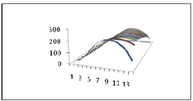
Figure 13. Characteristic 3D I2c vs V_wind with β=0-11.
Figure 13. Characteristic 3D Pout vs V_wind with β=0-11 V. CONCLUSION
From the simulation result above, it can be concluded that tha maximum mechanical power obtainde from a wind turbine is at a maximum wind speed at 12 m/s with a pitch angle β = 0 and value obtained for 25,513,942,39 watt.However, if the angle β is increased to 11 degrees with the maximum wind speed, it drops to 10168366.36 Watt. While the output current of an induction generator I2C when the maximum wind speed obtained with the value of λ = 8 and for all variants of the vlaue of β, the range of λ value ranged in number 8.
ACKNOWLEDGMENT
The Authors convey gratitude to the Ministry of Culture and Education, Indonesia, that has provided scholarships through the program of BPPS and National Strategic Research funded in 2010.
REFERENCES
[1] Li Nailu, Lv Yuegang, Xi Peiyu, "A Real-Time Simulation System of Wind Power Based on LabVIEW DSC Module and Matlab/Simulink", The 9th International Conference on Electronic Measurement & Instruments, ICEMI'2009, IEEE 2009, pp: 1-547 - 1-552)
[2] Liu Wenzhou, Cai Changqing, Zhang Zhuo,"Design of a Large Scale Wind Turbine Generator Set Yaw System",The 6th International Conference on Computer Science & Education (ICCSE 2011), August 3-5, 2011 IEEE 2011, Page(s): 915 - 918.
[4] A. B. Cultura II, , and Z. M. Salameh, "Modeling and Simulation of a Wind Turbine-Generator System", Power and Energy Society General Meeting, IEEE 2011, Page(s): 1 - 7.
[5] Aryuanto Soetedjo, Abraham Lomi, Widodo Puji Mulayanto, "Modeling of Wind Energy System with MPPT Control", International Conference on Electrical Engineering and Informatics (ICEEI), 17-19 July 2011, Bandung, Indonesia, IEEE 2011, pp: 1 - 6).
[6] E. Muljadi C.P. Butterfield, "PITCH-CONTROLLED VARIABLE-SPEED WIND TURBINE GENERATION", Industry Applications Conference, 1999. Thirty-Fourth IAS Annual Meeting, Vol : 1, IEEE 1999, Page(s): 323 - 330 vol.1.
[7] Xiyun Yang, Yuqi Cui, Hongsheng,Zhang, Ningning Tang, "Research on Modeling of Wind Turbine based on LS-SVM", International Conference Sustainable Power Generation and Supply, 2009. SUPERGEN '09. IEEE2009, Page(s): 1 - 6.
[8] Liang Gao, Associate Professor , Yangfan Luo, Master, "Simulation of Imitation of the Characteristics of Wind Turbine Based on DC Motor with Matlab International Conference Sustainable Power Generation and Supply, 2009. SUPERGEN '09. IEEE2009, Page(s): 1 - 5.
[9] Yuri Ulianov L6pez, Jose Antonio Dominguez Navarro PhD. Yuri Ulianov L6pez , "Small Signal Stability Analysis ofWind Turbines with Squirrel Cage Induction Generators", Transmission and Distribution Conference and Exposition, Latin America, IEEE/PES 2008, pp.: 1 - 10).
[10] Yishuang Qia, Qingjin Mengb, "The Application of Fuzzy PID Control in Pitch Wind Turbine", International Symposium on Power Electronics Electrical Drives Automation and Motion (SPEEDAM), 2010, Page(s): 391 - 395.
[11] Xin-yan Zhang ,Xiao-bo Zhang, Wei-qing Wang, "The Study of on Grid Wind Turbine Generator Made in China", Power and Energy Engineering Conference (APPEEC), 2010 Asia-Pacific, Page(s): 1 - 4 .
[12] Siegfried Heier, "Grid Integration of Wind Energy Conversion Systems," John Wiley & Sons Ltd, 1998, ISBN 0-471-97143-X.
[13] Reynaldo Zoro, Agus Purwadi, "The Use of Wind Turbine Structure for Lightning Protection System", STEI, ITB Bandung, IEEE-ICEEI 17-19 July 2011, pp.: 1 - 6.
[14] Amirullah, Ahmad Fauzan, “Desain dan simulasi system pengendali tegangan menggunakan kombinasi converter buck-boost dan inverter full-bridge pada pembangkit listrik tenaga angin”, ITS-Surabaya, 2010
[15] Zuhal, Zhanggischan, “Prinsip-prinsip Elektroteknik”, PT. Gramedia Pustaka Utama, Jakarta 2004.
[16] Lie Jasa, Putu Ardana, I Nyoman Setiawan, "Usaha Mengatasi Krisis Energi Dengan Memanfaatkan Aliran Pangkung Sebagai Sumber Pembangkit Listrik Alternatif Bagi Masyarakat Dusun Gambuk-Pupuan-Tabanan", Seminar Nasional Teknologi Industri XV, ITS Surabaya, Mei 2011, pp. B0377-B0384.