STUDY OF AN ADD-DROP FILTER USING A SINGLE BRAGG COUPLER
Rustam E. Siregar, Ayi Bahtiar, and A. Abrar
Department of Physics
Faculty of Mathematics and Natural Science, Universitas Padjadjaran Jalan Raya Jatinangor, Sumedang 45363, Indonesia
ABSTRACT
An add-drop filter that consists of a planar directional coupler with a single Bragg grating in one of its arms was studied. The calculation was based on coupled-mode equations in the form of a matrix equation by considering the studied structure. From the matrix equation, the propagation factors as eigenvalues of the eigenmodes was obtained, while the spatial structures of the eigenmodes are determined by the eigenvectors of the coupling matrix. By use of boundary conditions in individual waveguides, the drop output, return loss and total transmission, respectively, was calculated at the Bragg wavelength of 1550 nm. The results satisfy the requirements for Wavelength Division Multiplexing (WDM) applications.
Keywords : Bragg grating, add-drop filter, coupled mode equation, matrix
STUDI SUATU FILTER ADD-DROP DENGAN KOPLER BRAGG TUNGGAL
ABSTRAK
Telah dikaji suatu filter add-drop yang terdiri dari suatu papah directional coupler, dimana salah satu lengannya dibuat suatu Bragg tunggal. Perhitungan didasarkan pada persamaan moda tergandeng yang dibuat dalam bentuk persamaan matriks, dengan mempertimbangkan struktur yang dikaji. Dari persamaan matrik, diperoleh faktor-faktor propagasi sebagai nilai eigen dari modus-eigen, sedangkan struktur ruang dari modus-eigen ditentukan dengan vektor-vektor eigen dari matrik tergandeng. Output dari filter add-drop, kerugian balik dan transmisi total dihitung dengan menggunakan syarat-syarat batas dalam masing-masing pandu gelombang pada panjang gelombang Bragg 1550 nm. Hasil yang diperoleh memenuhi persayaratan untuk aplikasi Wavelength Division Multiplexing (WDM) dalam sistem telekomunikasi.
Kata kunci : grating Bragg, filter add-drop, persamaan moda tergandeng, persamaan
matriks
INTRODUCTION
been proposed and experimentally realized by Dong et al. (1996). Motivated by this filter, Erdogan (1998) has studied theoretically an asymmetric planar Bragg coupler. Instead of analyzing the coupled-mode equations, his calculations were based on the role of the waveguides’ thickness, with difference V-numbers of the waveguides and their separation on the filters’ performances. On the other hand, by employing coupled-mode equations, Orlov et al.(1997) analyzed theoretically the performance of an add-drop filter using a directional coupler with the same waveguides that consist of the same Bragg gratings. However, such filter is not easy to realize experimentally. Therefore, following the way of Orlov et al.(1997), we study the add-drop filter using a single Bragg coupler, where the two planar waveguides have the same V-numbers and lengths.
In this study, we use the same coupled-mode equations with those of Orlov et al. (1997)but with a single uniform Bragg grating without apodization. The coupled-mode equations are presented in the form of a matrix equation, and from its’ coupling matrix we solve the propagation factors as eigenvalues of the eigenmodes, while the spatial structures of the eigenmodes are determined by the eigenvectors of the coupling matrix. By using the propagation factors, eigenvectors, and boundary conditions in individual fibers, we obtain the eigenmodes. Finally, we calculate and analyze device parameters such as drop output, return loss and total return loss, respectively.
METHOD
matrix equation. The outputs of the structure were obtained by solving those equations numerically.
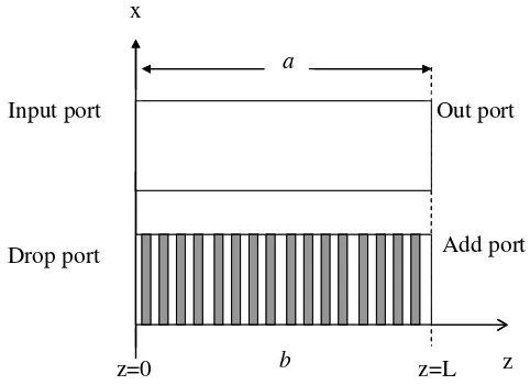
We consider the total TE electric field Ey (x,z,t) in the structure shown by Figure 1 as follows:
z b
a
z=L Add port Drop port
Input port
z=0
Out port x
z b
a
z=L Add port Drop port
Input port
z=0
Out port x
Figure 1. Structure of the studied add–drop filter.
[
]
{
[
]
i t}
yb z b i 2 z b i 1
ya z a i 2 z a i 1 y
e ) x ( e e ) z ( B e
) z ( B
) x ( e e ) z ( A e
) z ( A ) t , z , x ( E
ω β
β − β
β −
+ +
+ =
(1)
where A1(z) and A2(z) describe the forward and backward propagating modes in waveguide a, while B1(z) and B2(z) describe forward and backward propagating modes in waveguide b. This field satisfies the wave equation
0 E ) c / n (
Ey 2 2 2 y
2
= ω
+
∇ (2)
where the refractive index n2 is denoted as ) z , x ( n ) x ( n n ) z , x (
Gz and the Bragg wavelength λB = 2nsΛ. By substituting Equation (1) into Equation (2), and noting that each waveguide satisfies the following wave equation:
b
and using slow varying amplitudes and spatial averaging, one will finds the following coupled-mode equations (Yariv and Yeh, 1984) :
2
are the coupling constants between the corresponding modes. For simplicity, we assume the following relationships:
G
The coupled-mode equations (5) can be presented in a matrix form:
β where s is the propagation factor or eigenvalue of the operator / z with eigenmode a~ , and α~ is the spatial structure. The substitution of this form to Equation (9) will result
in the following secular equation
0
i structures, now we have eigenmodes {an} as:
α Now, from Equations (13) and (12), we obtain the modes as follows:
[
]
B1(0)=0, and at z = L, A2(L)=B2(L)=0. Therefore, from Equation (14) we obtain :=
By substituting Equations (11) and (12) into Equation (14), and employing the Cramer rule (Boas, 19843), we may find the values of {Ci} that are needed in Equation (14).
Return loss=A2(0)2/Ao2 (17)
Total transmission =1−
[
B2(0)2+ A2(0)2]
/Ao2 (18) where Ao=A(0).RESULTS AND ANALYSIS
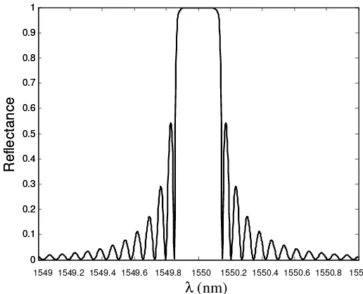
First, we check the reflectance of a single Bragg grating that we will use later in the add drop filter. By taking the parameters L = 1 cm, ns = 1.5, and κ = 5/cm, the reflectance as a function of ∆λ (= λ - λB) is shownin Figure 2. It shows that the central reflectance is 100% with a bandwidth of 0.3 nm around the Bragg wavelength λB = 1550 nm (Yeh, 1988).
-1 -0.8 -0.6 -0.4 -0.2 0 0.2 0.4 0.6 0.8 1
x 10-3 0
0.1 0.2 0.3 0.4 0.5 0.6 0.7 0.8 0.9 1
Delta lambda (um)
R
e
fle
c
ta
n
c
e
1549 1549.2 1549.4 1549.6 1549.8 1550 1550.2 1550.4 1550.6 1550.8 1551
λ(nm)
-1 -0.8 -0.6 -0.4 -0.2 0 0.2 0.4 0.6 0.8 1
x 10-3 0
0.1 0.2 0.3 0.4 0.5 0.6 0.7 0.8 0.9 1
Delta lambda (um)
R
e
fle
c
ta
n
c
e
1549 1549.2 1549.4 1549.6 1549.8 1550 1550.2 1550.4 1550.6 1550.8 1551
λ(nm)
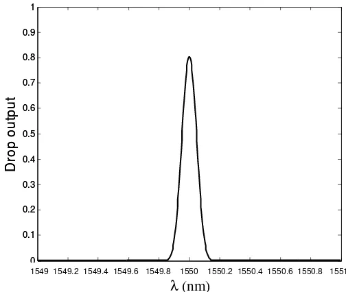
Second, the device parameters shown by Equations (16-18) are calculated using the following values: L = 1 cm, ns = 1.5, λB = 1.550 µm, κ = 5 cm-1, and κab = 0.5/cm. The drop out put as a function of ∆λ is shown by Figure 3. The drop output of 80% at the Bragg wavelength with a bandwidth of 0.1 nm or 12.5 GHz is observed. It shows also that there is no drop output found outside the bandwidth. Although the width at the base of the drop output (= 3 nm) is equal with that of reflectance in Figure 2, it becomes much smaller at the half peak (= 1 nm) and no side lobe is observed. This result indicates that these parameters are good parameters for an effective add-drop filter.
-1 -0.8 -0.6 -0.4 -0.2 0 0.2 0.4 0.6 0.8 1 x 10⁻³ 0
0.1 0.2 0.3 0.4 0.5 0.6 0.7 0.8 0.9 1
Delta lambda (um)
D
ro
p
o
u
tp
u
t
1549 1549.2 1549.4 1549.6 1549.8 1550 1550.2 1550.4 1550.6 1550.8 1551
λ(nm)
-1 -0.8 -0.6 -0.4 -0.2 0 0.2 0.4 0.6 0.8 1 x 10⁻³ 0
0.1 0.2 0.3 0.4 0.5 0.6 0.7 0.8 0.9 1
Delta lambda (um)
D
ro
p
o
u
tp
u
t
1549 1549.2 1549.4 1549.6 1549.8 1550 1550.2 1550.4 1550.6 1550.8 1551
λ(nm)
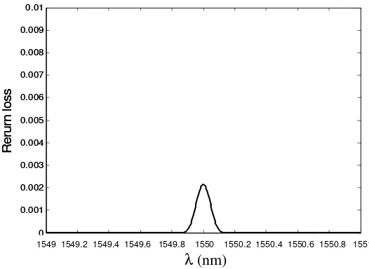
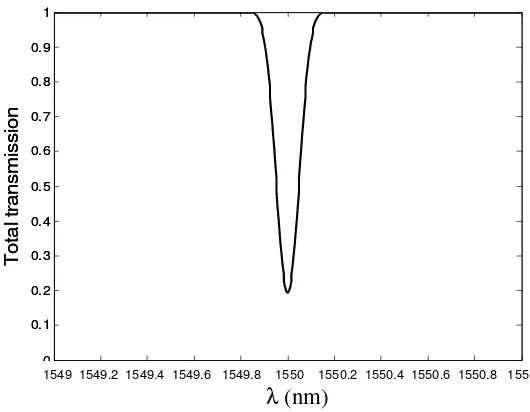
The return loss is shown in Figure 4; with the same bandwidth as shown in Figure 3. The return loss is very small, i.e. 0.02% at the Bragg wavelength which indicates that only a small fraction of light is reflected by the device. Figure 5 shows the total transmission of the device. It is clear that the total transmission of the Bragg wavelength is large. From the combination of the high drop output, very small of return loss and narrow return loss, this type of filter satisfies the requirements for wavelength-division multiplexer applications. Beside that, the process of the drop and add is very fast because the coupling between modes occurs without the help from outside the filter.
-1 -0.8 -0.6 -0.4 -0.2 0 0.2 0.4 0.6 0.8 1 x 10⁻³ 0
0.001 0.002 0.003 0.004 0.005 0.006 0.007 0.008 0.009 0.01
Delta lambda (um)
R
e
ru
rn
lo
s
s
1549 1549.2 1549.4 1549.6 1549.8 1550 1550.2 1550.4 1550.6 1550.8 1551
λ(nm)
-1 -0.8 -0.6 -0.4 -0.2 0 0.2 0.4 0.6 0.8 1 x 10⁻³ 0
0.001 0.002 0.003 0.004 0.005 0.006 0.007 0.008 0.009 0.01
Delta lambda (um)
R
e
ru
rn
lo
s
s
1549 1549.2 1549.4 1549.6 1549.8 1550 1550.2 1550.4 1550.6 1550.8 1551
λ(nm)
-1 -0.8 -0.6 -0.4 -0.2 0 0.2 0.4 0.6 0.8 1 x 10⁻³ 0
0.1 0.2 0.3 0.4 0.5 0.6 0.7 0.8 0.9 1
Delta lambda (um)
T
o
ta
l t
ra
n
s
m
is
s
io
n
1549 1549.2 1549.4 1549.6 1549.8 1550 1550.2 1550.4 1550.6 1550.8 1551
λ(nm)
-1 -0.8 -0.6 -0.4 -0.2 0 0.2 0.4 0.6 0.8 1 x 10⁻³ 0
0.1 0.2 0.3 0.4 0.5 0.6 0.7 0.8 0.9 1
Delta lambda (um)
T
o
ta
l t
ra
n
s
m
is
s
io
n
1549 1549.2 1549.4 1549.6 1549.8 1550 1550.2 1550.4 1550.6 1550.8 1551
λ(nm)
Figure 5. Total transmission as a function of ∆λ; L=1cm, κ =5 cm-1, and κab=0.5 cm-1.
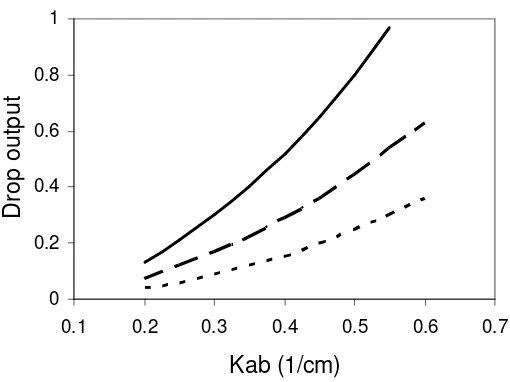
Finally, we studied the influence of the coupling between two co-propagating modes, κab, on the drop output by calculating the drop output as a function of κab for κ
0 0.2 0.4 0.6 0.8 1
0.1 0.2 0.3 0.4 0.5 0.6 0.7
Kab (1/cm)
D
ro
p
o
u
tp
u
t
Figure 6. Drop output as a function of κab for κ = 5 cm-1, L = 0.9 cm (---), L = 0.95 cm (__ __), and L = 1 cm (___).
CONCLUSION
We have studied an add-drop filter using a planar directional coupler with a single Bragg grating in its arms with a Bragg wavelength of 1.550 µm. After we solved the coupled-mode equations, the filter parameters were calculated. The results are: for
ACKNOWLEDGMENT
We thank TPSDP for funding this research through Research Grant Project TPSDP Batch III, ADB Loan No. 1792-INO.
REFERENCE
1. Dong, L., Hua, P., Birks, T. A., Reekie, L., Russell, P. S. J. (1996). Novel add-drop filters for wavelength-division-multiplexing optical fiber systems using a Bragg grating assisted mismatched coupler. IEEE Photonics Technology Letters, 8(12), 1656-1658.
2. Erdogan, T. (1998). Optical add-drop multiplexer based on an asymmetric Bragg coupler. Optics Communication, 157, 249-264.
3. Orlov, S. S., Yariv, A., van Essen, S. (1997). Coupled-mode analysis of fiber-optic add-drop filters for dense wavelength-division multiplexing. Optics Letters, 22, 688-695.
4. Yariv, A., Yeh, P. (1984). Optical Waves in Crystals, New York : Wiley.
5. Zill, D. G. (1982). A first course in differential equation with applications (pp. 375-380). Boston : Prindle, Weber & Schmidt.
6. Boas, M. L. (1983). Mathematical methods in the physical sciences (pp. 91-93). New York : John Wiley.