INDUSTRIAL PHOTOGRAMMETRY -
ACCEPTED METROLOGY TOOL OR EXOTIC NICHE
Werner Bösemann
AICON 3D Systems GmbH, Biberweg 30C, D-38114 Braunschweig, Germany – [email protected]
Commission V, WG V/1
KEY WORDS: Industrial photogrammetry, close range, mobile, industrial application, 3D point measurement, optical CMM
ABSTRACT
New production technologies like 3D printing and other adaptive manufacturing technologies have changed the industrial manufacturing process, often referred to as next industrial revolution or short industry 4.0. Such Cyber Physical Production Systems combine virtual and real world through digitization, model building process simulation and optimization. It is commonly understood that measurement technologies are the key to combine the real and virtual worlds (eg. [Schmitt 2014]).
This change from measurement as a quality control tool to a fully integrated step in the production process has also changed the requirements for 3D metrology solutions. Key words like MAA (Measurement Assisted Assembly) illustrate that new position of metrology in the industrial production process.
At the same time it is obvious that these processes not only require more measurements but also systems to deliver the required information in high density in a short time. Here optical solutions including photogrammetry for 3D measurements have big advantages over traditional mechanical CMM’s.
The paper describes the relevance of different photogrammetric solutions including state of the art, industry requirements and application examples.
1. INTRODUCTION
Accepted tool or exotic niche. As late as in the year 1984 Gottfried Konecny states in his textbook on Photogrammetry: “Terrestrial photogrammetry has … some disadvantages … and is used only in special applications.” [Konecny, Lehmann 1984]. Industrial applications were even less favoured. The need to process and develop the film first, thus delaying the delivery of results for hours or even days made the technology a very exotic tool in certain applications
This changed with the availability of digital cameras and powerful and yet affordable computing devices starting in the late eighties. Among the pioneers in digital photogrammetry was Prof. Wilfried Wester-Ebbinghaus. He developed digital solutions necessary for image measurement and camera calibration, bridging large scale photography with digital scanning and reseau technology to form high end photogrammetry solutions for industrial applications [Wester-Ebbinghaus 1990].
Newer generations of digital cameras with larger sensors fostered the ability to deliver 3D measurement results on multiple points immediately after the measurement was taken, nowadays sometimes even in real-time. These features, together with highest accuracy and high flexibility and mobility of camera based measurement systems creates the core advantages of industrial photogrammetry up to now.
First systems developed with focus on industrial applications were using a single handheld camera to be moved around the objects and used mainly in medium to large size industrial structures. Typical examples of such systems are for example the VSTARS system from GSI or the DPA from AICON 3D
Systems. Figure 1 shows an example of such a system package with camera, notebook, scale bar and targets. A key feature is the high portability of the system allowing its use on-site even in difficult or unstable environments.
This forms an important feature against Coordinate Measuring Machines (CMM) which have been dominating the industrial 3D metrology sector for decades.
Figure 1: AICON DPA
Figure 2: Measurement systems with relation to size and accuracy
Yet photogrammetry is capable to cover a wide area of applications in terms of volume and accuracy. Figure 2 indicates the huge potential of photogrammetry in the market.
Multi camera solutions offer additional possibilities for online and real-time measurements. Time resolved measurements also allow for dynamic measurements resulting in new applications for tracking and positioning. Combined with the capability to measure multiple points simultaneously such solutions are not just a quality control tool but can be part of the manufacturing process, sometimes also referred to as Measurement Assisted Assembly (MAA).
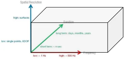
Another group of applications is more concerned with the analysis of the geometric change of a part under defined conditions. These applications are typically related to motion analysis, deformation testing or vehicle dynamics. Here photogrammetry offers unique possibilities to simultaneously measure hundreds or thousands of points, calculate deformations and visualize in an image or an image sequence.
Figure 3: Frequency versus spatial resolution
Another big change in industrial metrology over the past twenty years was the growing requirement for dense 3D surface data, not only for reverse engineering of components but also as a standard inspection technique. Even so most inspection plans of industrial parts are still written for classical CMM’s using single point probing, a color map showing the deviations against a CAD model can offer much easier display and understanding of the problems arising from these deviations.
Many stationary or portable CMM’s are therefore equipped with laser line scanners to deliver such surface data. But there are also systems on the market that use photogrammetric techniques for 3D object scanning although they typically do not come under that name. They use either correlation or white light fringe projection technologies. The first group of systems is mainly used in component testing and less in industrial inspection. Typical
suppliers are the German company Dantec or US based company Correlated solutions.
The second group of systems has, over the years, become a real standard in industrial metrology and is probably the most widespread system type based on photogrammetry. Figure 3 shows a typical scanner with a stereo camera setup and a digital projector.
Figure 4: Fringe projection
Corresponding points are typically found through phase shifting combined with a coded light approach [Breuckmann 1994]. First systems appeared in the early 90’s form Steinbichler Optotechnik and Breuckmann GmbH. Today many suppliers exist on the market, notably next to Steinbichler and Breuckmann mainly the ATOS systems from German supplier GOM. Systems use either one camera and a projector or two cameras and a projector. Those stereo systems can either triangulate between one camera and a projector or between the two cameras.
Figure 5: Breuckmann StereoSCAN
2. INDUSTRIAL REQUIREMENTS
2.1 Feature based inspection
Based on the high accuracy of CMM’s in combination with precise manufacturing equipment accuracy requirements for portable metrology systems are rather tight. As a rule of thumb only 10% of the tolerance are allowed to be used by the measurements systems accuracy.
Figure 6: GD&T description of a simple part (Source: Bill Tandler, Multimetrics Inc.)
At a typical automotive tolerance of 1 mm, the measurement system must be capable to be accurate within 0.1 mm. Some features in the drawings today even show tolerances of 0.5 mm and less.
Figure 7a: Scanned part …
Figure 7b: …. and color deviation map
Also the definitions for measurement accuracy are rather strict. While in photogrammetry usually a simple standard deviation is stated as system accuracy, most industry standards ask for maximum permissible errors (MPE).
2.2 Traceability and certification
Another important topic is reliable and comparable certification about the accuracy of industrial measurement systems. In 1996, a joint working group “Optical 3-D Measurement Techniques” was established by the Society for Measurement and Automatic Control (GMA) within the Association of German Engineers and Electrical Engineers (VDI/VDE) and the working group “Close -Range Photogrammetry” of the German Society for Photogrammetry, Remote Sensing and Geoinformation (DGPF) to draft a guideline for the evaluation of the accuracy of image-based 3-D measuring systems. Meanwhile, three parts of the new guideline VDI/VDE 2634 were published (in German, and translated in English). Part 1 describes acceptance and verification methods for systems with point-by-point probing whilst Part 2 is concerned with systems based on area scanning [VDI/VDE 2002]. Part 3 is for combined point-by-point and scanning solutions
Figure 8: Test field at AICON (above) and typical example of a length measurement error diagram
Photogrammetric systems typically deal with point-by-point probing, i.e. Part 1 of the guideline. The test procedure is based on the 3-D measurement of a spatial test field containing at least 7 measuring lines (Fig. 8 left). Along each measuring line a number of features, e.g. circular targets, suitable for precise optical probing is placed. At least 5 calibrated distances between the targets on each measuring line have to be determined by means of an optical measuring system. The comparison of the distances derived from the optical measurements with their
-0,15
calibrated values results in three-dimensional length measurement errors (Fig. 8 right). The maximum permissible length measurement error is the criterion for the quality of the measuring system. This is a much stricter description of accuracy and had led to some confusion in the market as some companies continued to promote accuracies based on simple standard deviations, but the consequent testing of systems according to VDI/VDE 2634 has led to a much higher acceptance of photogrammetry in the industrial market.
2.3 Integration into production environment
The ability to control a part for its dimensional correctness is only one aspect in the use of 3D metrology in general. System providers are more and more required to deliver solutions into specific manufacturing environments. Obtaining measurement values is only one step, analysis of the data to derive feedback information into the manufacturing process requires both knowledge about those processes as well as integration into the processes. Those interfaces include links to quality control systems, statistical process control, manufacturing guidance systems and of course production machinery.
3. STATE OF THE ART
The use of photogrammetry in industry has not fundamentally changed over the past 5 years. A good review of the authors view on state of the art has been presented in [Bösemann, W. (2011)]. Since then improvements in camera technology, resolution, speed, computing power have further enhanced the systems and its use. This chapter re-emphasizes some important points and adds selected improvements in the technology. It also includes now white light scanning systems as these are also very often combined with photogrammetry solutions to extend performance and reach in certain applications.
3.1 High-speed camera systems
Commercially available high speed can have frame rates of more than 7000 frames per second at 1.0 megapixel camera resolution but have very limited recording time. Also online or realtime processing is not possible. With the use of a build-in processor for real-time data processing image coordinates of targeted points can be found in real-time thus reducing the data stream considerably, allowing basically unlimited image capture with high frequency.
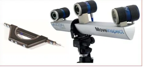
Figure 9: MoveInspect HF camera
Such a camera is the MoveInspect HF camera from AICON. At 4 megapixel resolution the camera is able to measure moving parts at 500 Hz, or 1000 Hz at reduced resolution, over a virtually unlimited period of time. Through flash times of down to 10 microseconds objects moving at more than 50m/s can be measured. The camera has a protective housing for use in rough industrial environments and adaptive illumination for the scene
3.2 Multi camera systems
Single camera handheld photogrammetry solutions where images are taken sequentially offer superior accuracy and also flexibility but still have an important disadvantage. They lack online and real-time performance to offer immediate results and feedback.
Two or more cameras connected to a processing unit deliver much faster results. When synchronized properly they can even measure in unstable environments or moving objects. Online systems are capable to measure multiple points in real time at sample rates of 100 Hz and more. Single points or objects can be tracked for a variety of applications in positioning, object tracking, process control. Probing is a special variation of tracking where a targets are applied to a handheld 3D probe. The 3D probe is equipped with an, often exchangeable, probe tip. This mode of operation brings optical inspection closer to principles of CMM operation. This is partly considered to be a drawback as key features of optical metrology, like touchless measurement or fast measurement of multiple points, are lost. On the other hand the similiarity to CMM style of operation makes it easier to adopt existing measurement strategies and is better accepted by users familiar with CMM’s.
The Metronor light pen was one of the first devices to combine photogrammetry and tactile measurements. Today a variety of systems like the MI.Probe from AICON 3D Systems with exchangeable probe tips, automatic probe identification, wireless operation and status controls on the probe are available.
Figure 10: 3-camera system with handheld probe
The bottleneck in those systems was the limitation in bandwidth of the digital camera interface. The AICON TubeInspect system was one of the first systems to synchronize 16 1.3 megapixel cameras and interface to a single PC through a Firewire A interface. Newer technologies like Gigabit Ethernet and USB 3 allow for even higher data rates and make it possible to connect 16 and more cameras with 8 megapixel camera resolution with refresh rates of several measurements per second. This technology makes it possible to create multi camera grids to cover larger measurement areas.
thus making it an ideal tool for process integrated measurements up to applications in measurement assisted assembly.
Figure 11: Sketch of a multi camera setup
3.3 Color light scanning and back projection
The term “white light scanning” used with the type of fringe projection systems described above dates back to the early systems that would typically use halogen lamps emitting white light in the projection units. Newer generation of scanners the used LED technology. Because blue LED’s typically have the highest light intensity they soon became a standard in those scanners and sometimes the term blue light scanning was used instead.
On the other hand the color of the projected light interacts with the color and reflectance properties of the surface to be measured – and to some extend also the sensitivity of the sensor, properties of the lens and filters. Blue light for example does not work well with reddish surfaces like clay models in design studios. But they complement well with most metallic surfaces and are therefore mostly a good choice in industrial applications. A detailed investigation on the topic can be found in [Mongon et. al. (2013)].
Another mayor influence is the reflectance of the surface. Glossy or shiny surfaces are difficult to measure and often need preparation, e.g. with a matte powder spray. The effect is reduced with the intensity of the light projected. Therefore high power projectors are advantageous in those situations, the also reduce the influence of ambient light.
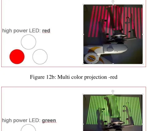
New generations of projectors use digital projectors based on DLP technology. The StereoScan Neo from AICON uses a light engine with three high power LED’s. that can be used separate or combined
Figure 12a: Multi color projection - blue
Figure 12b: Multi color projection -red
Figure 12c: Multi color projection - green
Figure 12d: Multi color projection – white
The adaption of the color of the projection to the surface color leads to better scan data. The combination of the three high power LED’s to white projection improves performance on shiny surfaces.
Other advantages of digital projection are the possibility to project stripes in different orientations and masking technologies to exclude unwanted areas.
Digital projection units in the scanner also give way to a completely new use of the measurement device. Many applications require immediate interaction based on the results. Back-projected on the object they can be used for various tasks like marking defective areas, positioning objects and many other applications.
3.4 Dynamic referencing
The possibility to track not only multiple points but also multiple objects representing multiple coordinate systems can be used for a very unique feature of photogrammetric systems referred to as dynamic referencing. If an area at or around the object is considered to be stable, and measurement points with known coordinates are available or are created in an initial step prior the actual measurement, the position of the cameras can be recalculated in every following measurement. This method can be used in two different ways. The first is to eliminate errors through unstable camera positions. As reference and measurement points are captured and calculated from the same images, the camera position is eliminated from the error budget. Of course the procedure requires a stable, precise and well defined geometry of the reference. The second mode is to increase the measurement volume of the camera setup. A reference is created on a large part. e.g. through off-line photogrammetry with high precision and a fixed multi camera system with reduced volume but high accuracy is moved along the part. The system can automatically align with the reference giving seamless measurement results always with respect to the reference. The same procedure is also used to align patches from white light scanning devices on large reference grids created by photogrammetry.
Figure 14: Dynamic referencing to increase measurement volume
.
3.2 Combined solutions
Many measurement applications have conflicting requirements concerning accuracy, size, resolution etc. Especially large objects often require both measurement of local features with highest precision and/or resolution and at the same time end-to-end dimensions but with different tolerance requirements. A simple example is that the diameter of a hole needs to be measured with a tolerance of a few microns whereas the distance of two holes of several meters still needs to be controlled within 0.1 mm or 0.2 mm. As accuracy of photogrammetry is always a function of scale it is difficult to configure a system that delivers large volume measurements with tight local tolerances at the same time. Also the different systems described offer different capabilities in terms of resolution, frequency and accuracy. Therefore it is quite common to combine different systems.
A common and well established combination is the use of single camera photogrammetry to create reference point networks for 3D scanning. Most objects are to complex to be captured in a single scan. Therefore multiple scans have to be aligned in a
single model. Objects with sufficient geometry can be merged by direct alignment of the scans.
Figure 15: Direct alignment of scans
For larger or flat objects accuracy detoriates rapidly with object size or on flat objects. Here index marks are placed on or near the object and measured with a suitable photogrammetry system. The use of these control points in the alignment process allows the transfer of the global accuracy to the high resolution model.
Another method is the measurement of the scanner position. These positions are than used in the alignment process. A target frame is mounted around the scanner and measured with a large volume optical tracking system like 3D Arena. Again this method allows the combination of high global accuracy fom the tracking system with high resolution from the scanner.
Figure 16: Scanner with target frame
4. APPLICATION EXAMPLES
4.1 Measurement assisted assembly – adjustment and final inspection of aircraft passenger doors
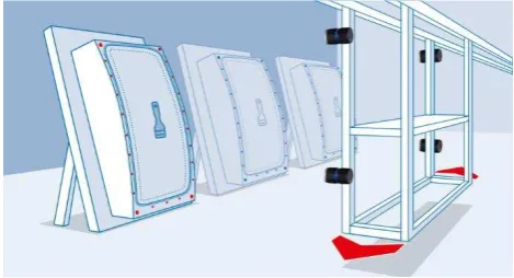
In a final step in production of passenger doors for Airbus aircraft the door is mounted in a special test jig and the door lock has to be adjusted. In the procedure more than 250 feature points have to be controlled during that adjustments. This procedure was originaly performed with a single point measurement device and was extremely time consuming because all points had to be remeasured after every adjustment step. The new solution was a photogrammetry solution
position and step measurement simultaneously during the alignment process.
Figure 17: Special targets to measure flush and gap
Figure 18: Online measurement during door adjustment
In the final inspection hidden points are measured with a handheld wireless probe (optically tracked). The operator is guided through each step of the measurement by a wizard in the application software
Figure 19: Moveable camera platform
As the system is mounted on a guiding rail it can be moved to the different jigs in the production line with ease.
4.2 Inspection of gear transmission casings
For the measurement of components with a complex geometry and surface structure like crankcases or gear transmission casings, white light scanners offer fast and highly precise results. The contact-free optical scanning technology ensures an effective and affordable measuring performance.
Figure 20: Scanning of a crankcase
With the aid of the software OPTOCAT, individual data recordings of the component are produced, thereafter aligned and then joined to a homogeneous triangulated mesh. In a second step, the generated data sets are evaluated with the aid of a special inspection software (e.g. PolyWorks/Inspector™ by Innovmetric Software Inc.) in order to assess the geometry.
Figure 21: Color deviation map of a crankcase
Even smallest shape deviation can be identified faster, easier and at higher accuracy. And also the overall digitization process together with the subsequent data comparison leads to valuable time and cost savings.
4.3 Reverse engineering of clay models in design studios
Automotive designers still manufacture 1:1 clay models of automotive prototypes. These models are used to try changes in the design or to test different versions of add-on parts like mirrors, bumpers or others. All changes in geometry must be documented and brought back into the CAD model of the car. Index marks are normally not allowed on the expensive clay models. NaviScan with 3D Arena now allows for easy scanning of full size car models.
Figure 22: 3D Arena in a design studio with cameras in the ceiling and reference marks on the floor
As 3D Arena is normally out of sight in the ceiling of the design studio, the designer can enjoy an entirely undisturbed look at the model. It can be viewed and processed from different angles without impeding stationary milling or measuring machines
4.4 3D Gas turbine inspection
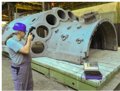
Gas turbines with dimensions of up to 13 meters in length, 5 meters in height and weighing up to 400 tons: components of this magnitude represent an enormous challenge in production. The gas turbines must meet highest requirements, as they are exposed to highly demanding operating conditions: extremely high combustion temperatures, large centrifugal forces as well as vibrations and transient loads. Exact dimensional accuracy is therefore of prime importance to ensure maximum stability.
Figure 23: Image capturing with high-resolution digital camera (Image: Siemens)
The data for the CAD comparison is obtained with a handheld high-resolution digital camera. Individualized, coded targets or adapters are placed at all object features relevant to the inspection. The object is photographed from different directions with the digital camera, so that all significant areas are captured. These photographic images are processed in the fully automatic software AICON 3D Studio. The software automatically calculates the 3D coordinates of all targeted points.
Figure 24: Exemplary analysis in SpatialAnalyzer (Image: Siemens)
4.5 Dynamic measurement – MoveInspect HF (IWES)
For rotor blades in wind power stations, reliable predictions concerning the durability are indispensable. When do rotor blades fatigue, when do material defects get visible? Life-cycle monitoring is carried out with four high-resolution digital cameras, each mounted on a tripod and positioned around the blade. By this method, any displacement of the entire specimen can be detected.
Figure 25: Static and cyclic load test
Figure 26: Inspection of a rotor blade (Image IWES)
A modified MoveInspect HF camera is used to measure blade deflections in static and cyclic load test with the following specifications:
Max. deformation: up to 20 meters
Data frequency: > 100 Hz, real-time measurements possible Accuracy: < 2 mm, depending on object size
Record period: unlimited Configuration: portable system
4.6 Vehicle Dynamics
An important application area for industrial photogrammetry is vehicle dynamics testing e.g. non-contact high speed monitoring of wheel motion at test drives. The impact of different types of bearings on both axles and wheel positions as well as drivability is one of the questions that can be answered by an effects analysis.
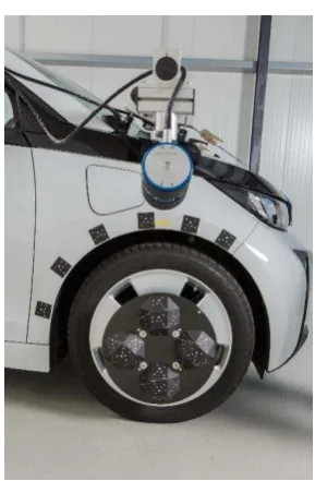
Figure 27: Test preparation: Camera, wheel adaptor and reference on fender
A single-camera technology is applied to measure the position and orientation with high frequencies of up tp 500 Hz. A camera is mounted on each wheel to be measured, which simultaneously captures the fender as a stationary reference system and the wheel as a second rigid body. Specially coded measurement targets on the bodywork identify the vehicle coordinates system. The wheel
is signalized with an adapter in lightweight construction (CRP). Additional points on the car body allow for dynamic referencing to eliminate camera movement during the test.
Figure 28: Test drive on Belgian block
A variety of maneuvers are driven where for example the vertical dynamics are examined through straight exits on bad roads. To measure the lateral dynamics, standardized driving maneuvers such as the VDA (German Automobile Industry Alliance) lane change (according to ISO 3888-2) are performed, but also open-loop maneuvers such as stationary circle and sinusoidal steering.
4.7 Structural testing of a helicopter cabin
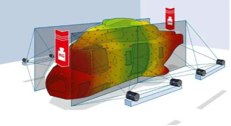
The task is dynamic 3D deformation measurement of a complete helicopter cabin (L appr. 10m) during load test. Measurement takes place within a high force actuator test rig (load simulation, hard landing,…).
Figure 29: Test setup
It was required to provide higher point density than actual string gauges and to allow large deformation without data loss. Test until breakage causes risk for measurement system and due to the structure of the test rig line of sight was heavily obstructed. Data had to be provided in one global coordinate reference frame (helicopter system) and to be synchronized with the actuator system.
Figure 30: Deformation chart
5. CONCLUSIONS
The strong and growing demand for fast on-site quality control and the availability of mature system solutions has significantly improved both the need and the confidence of the industrial system users and decision makers in this technology.
Available standards for traceability and certification, available tooling as well as interfaces to common inspection software have turned photogrammetry into a standard tool in many industrial measurements, combined with unique additional features, like the capability to measure multiple points simultaneously at high frequencies. The application examples shown in this paper can only give a glimpse on the future possibilities for industrial photogrammetric solutions.
The main drawback at the moment is still the requirement to use targets for highest accuracy. This topic is partly addressed by white light scanning systems with their ability to deliver high resolution geometry data but the challenge remains to develop algorithm for direct feature measurement. The possibility to develop solution-oriented systems, like installations addressing MAA applications, will further increase the number of photogrammetry installations in industrial measurements.
Other techniques light time of flight cameras or structure from motion (SFM) still lack the accuracy required in industrial inspection and are limited to deliver starting values for precise measurements systems or observation tasks like collision detection.
Yet the conclusion is that, especially in consideration of the market share of white light scanners, photogrammetry systems are no longer a niche application but an accepted tool in many areas of industrial manufacturing.
REFERENCES
Bösemann, Werner (2011): Industrial photogrammetry – Challenges and opportunities, Videometrics, Munich 2011
Breuckmann, B. (1993): Bildverarbeitung und optische Messtechnik in der industriellen Praxis, Franzi Verlag GmbH, pp. 273-295
Breuckmann, B. (1994): Vorrichtung zur optischen Vermessung von Entfernungen und räumlichen Koordinaten, Patentschrift DE4415834
Konecny, G., Lehmann, G. (1984): Photogrammetrie , 4. Auflage, Walter de Gruyter, Berlin New York 1984
Mongon, W. et. al. (2013). What light color should a white light scanner use? Journal of the CMSC, Spring 2013 issue
Schmitt, R. (2014) Coordinates as a Service – Messtechnik für die Industrie 4.0. Vortrag 9. VDI Fachtagung Koordinatenmesstechnik in der Physikalisch Technischen Bundesanstalt, Braunschweig
Tandler, Bill. The SmartGD&T™ Pocket Guide, MultiMetrics Inc., Menlo Park, CA, USA
VDI/VDE, 2002: VDI/VDE Richtlinie 2634 Optische 3-D Messsysteme. Beuth Verlag, Berlin.
Wester-Ebbinghaus, W. (1990): High precision industrial photogrammetry, Photogrammetric Record 13 (76), p. 603-608
www.aicon.de: AICON 3D Systems GmbH Homepage 2011-2016
www.geodetic.com: Geodetic Systems Incorporated Homepage 2011-2016
www.gom.com: Gesellschaft für optische Messtechnik mbH Homepage 2011-2016
