HUMAN VISION PATHOLOGY DIAGNOSTICS BY PHOTOGRAMMETRICS MEANS
A.B. Murynin1, V.A. Knyaz2, I.A. Matveev1
1
Dorodnicyn Computing Centre of the Russian Academy of Sciences, Moscow, Vavilova,40 - [email protected] 2
St. Res. Institute of Aviation Systems (GosNIIAS), 125319, 7, Victorenko str., Moscow, Russia - [email protected]
Commission V, WG V/5
KEY WORDS: Human vision pathology, Close-range Photogrammetry, Anthropometric measurements, Pathology diagnosis
ABSTRACT:
One of the reasons of such vision pathology as human stereoscopic vision capability dysfunction is an asymmetry of a human face. As a rule, such dysfunctions occur as early as in the babyhood, when diagnostic methods applied for adults are ineffective. Early diagnostics and prophylaxis could help in treatment of such pathology and face 3D modeling is one of the promising ways to solve this problem.
1. INTRODUCTION
Continuous development of computer means, digital image sensors and image processing algorithms allowed elaborating new technologies of remote sensing and noncontact measurement. Various types of systems employ different physical principles of measurement like laser triangulation, photogrammetric approach, phase shift etc, and allow estimating object surface coordinates with high precision and density. These systems are successfully used in wide area of applications, from industry to medicine and arts.
One of perspective applications of these technologies in medicine is automated computer systems for vision human pathology prognosis and prophylaxis employing 3D human face model constructed by the means of computer vision system (Knyaz, 2005, Knyaz, 2007). This approach is based on relationship between human stereoscopic vision capability dysfunctions and presence of face asymmetries. As a rule, such dysfunctions occur as early as in the babyhood, when diagnostic methods applied for adults are ineffective. Method under consideration allows pathology detection in proper time.
2. SYSTEM FOR 3D FACE MODEL CONSTRUCTION
2.1 Anthropometric measurements approach
Anthropometric measurements i.e. determination of human body parameters is an important task in many application fields. Employing 3D vision systems allows obtaining new type of data for processing and extraction of anthropometry parameters and gives new research opportunities, which were impossible before.
Employing 3D models of face and other human body parts gives irrefutable advantages over 2D data (photograph) analysis like:
Direct representation of quantitative data about the object
Better obviousness
Reduction of necessary number of images required to have full picture of object
Better level of operation planning and its results evaluation.
Remote sensing system based on photogrammetric principles is a convenient tool for obtaining real data on shape of human face and body parts, performing necessary measurements and comparing parameters. Photogrammetric measurement system allows estimation of coordinates of a given object point by two images taken from different points of view by cameras of the stereoscopic system. For calculating 3D coordinates of object point it is necessary to know positions of cameras in some coordinate system (stereo-system orientation) and locate the position of the point in both images obtained by the stereo-system (task of stereoscopic identification of correspondent points).
2.2 Photogrammetric stereo system
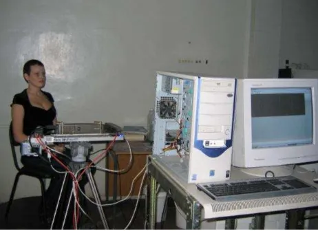
In order to be used in anthropometric applications remote sensing system should satisfy several specific requirements like safety and comfort for object of registration (i.e. human) and fast image registration, which is necessary since human cannot stay still for a long time. Apart, remote anthropometric measurement system should determine surface coordinates with high precision and supply it in a form of digital 3D model (preferably, textured) for further analysis. The system elaborated considering these basic requirements includes (See Fig.1):
o Two technical vision cameras designed for capturing monochrome images of human in structured light, which are used for calculating 3D coordinates of face surface;
o Color high resolution photo camera for obtaining color image of person, which is used for realistic texturing of 3D model;
o Portable DLP projector for computer-controlled illumination, which facilitates the task of stereoscopic identification of correspondent points;
o Personal computer.
Figure 1. Photogrammetric system
In order to estimate 3D coordinates of object surface point (A) and to construct its 3D model it is necessary to find 2D coordinates of each visible point in left (a_l) and right (a_r) images (solve the task of stereoscopic identification of correspondent points). Then 3D coordinates of point (A) are calculated using data of stereo-system orientation, cameras positions (See Fig.2).
Original coded illumination of object is used in the system that facilitates automated identification of correspondent points and allows minimizing number of frames while preserving high precision and density of measured points. In order to construct a 3D model with full density 17 image frames are used, that correspond to approximately 0.5 second of capture process.
Figure 2. Measurement technique
Systems’ precision is ensured by preliminary calibration of it, which is determining inner orientation parameters. The calculation is performed by the technique of least squares as a problem of calculating unknown parameters from observation of test object, which spatial coordinates are known a priory.
In order to automate calibration process original coded patterns are used as reference point markers (Knyaz, 2000), allowing automatically detecting, identifying, and precisely measuring
reference point’s coordinates in images. Appearance of the test object (test scene) used for calibration and orientation of the system is shown in Fig. 3.
Figure 3. Stereo system calibration
External system orientation is made for estimation of position and orientation of cameras in the coordinate system established by special test object (See Fig.3). As a result orientation procedure performed by the test object images coordinates and angles of camera rotation are determined in the given coordinate system. Further, object surface coordinates are outputted in this coordinate system.
The system main technical characteristics are: o Image capture time (scanning time) - ~0.5 sec ; o 3D model calculation time – 10 sec ;
o Density of points with measured coordinates – 10-25 points per mm ;
o Spatial precision of coordinates – 0.5 mm ;
The system performs the following functions:
o Capturing and obtaining required number of facial images for further 3D model generation ;
o Construction of high precision face 3D model ; o Texturing of this model.
3D coordinates of object surface are obtained from sequences of images from monochrome cameras; high resolution color camera image is used as texture. Texturing of 3D model is done automatically by the results of orientation procedures.
The hardware complex in process of 3D face model acquisition is shown in Fig. 4
Figure 4. 3D face model acquisition
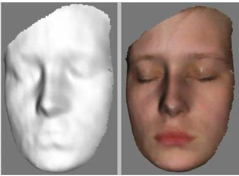
The sample of face 3-D model is shown in Fig.5 for different representations: grid representation (3-D surface only, no face texture applied), and the model with application of color texture. For texture mapping high resolution image captured by still digital camera is used. Texturing is carried out in automated mode using results of still digital camera calibration and orientation. Texturing of 3D model allows to expert to identify anthropometric points needed for investigation.
Figure 5. Sample of face 3-D model
3. ALGORITHM OF STEREO FACE RECONSTUCTION
In order to reconstruct accurate 3-D face model we use general stereo reconstruction algorithm.
To reconstruct the 3D-shape of some object we use two images of this object that are obtained from different points of view. (also referred to as disparity map).
D x y
( , )
(( , ),( ', '))
x y
x y
Where (x,y) – coordinates of the point in the basis image and
(x’,y’) coordinates of correspondent point in the scanned image.
The correspondent point can be estimated as:
( ' , ' )
arg max
~
(
,
( ' , ' ))
( ', ')
x y
x y
x y L R
- correlation function used for estimation of resemblance of regions
L,
R in left and right images of the stereo pair.This system specific conditions (geometry of apparatus and object properties) result in some modifications of algorithm that can be divided into three classes: modifications of regions the algorithm works with, modifications of applicable correlation functions and modifications in the structure of algorithm in whole (Murynin et al, 1998). Some important features of this modifications are briefly described below.
Modifications of regions the algorithm works with follow arise from optimization of size of the scanned region. It means that the correlation function region must contain enough structural elements, that means it must be sufficiently large in comparison with object surface details. On the other hand the correlation function region would be sufficiently small if compared to large details of face relief.
Modifications of applicable correlation functions are performed to take into account variations of contrast, brightness, and other characteristics of images (Murynin et al, 1998).
The general algorithm is restructured in whole for solving the following problems. For a given system geometry the disparity variations are not more than several pixels. It is a very coarse scale for performing subsequent calculations. This problem is put away by introduction of super-resolution. Super-resolution is used to increase the granularity of scale by employing information from neighboring points. Simple and thus fast method of increasing resolution is developed in (Murynin et al, 1998).
Other modifications of the general algorithm are based on the techniques of the reverse pass of correlation algorithm and on the pyramidal data representation.
It is important to consider possible mistakes of correlation algorithm. If a studied surface has a highly-regular structure several regions can be found in a scanning image that resemble a certain region in a basis image. In this case correlation function has several local maxima in a scanned region, and it
may happen, that ‘correct’ maximum is not a global one. So, a
wrong match can be selected for a point and wrong disparity can appear. The other case, when correlation algorithm can generate an error is the absence of good texture. In this case correlation function has no maximum, any point in scanned region can be corresponding and disparity can receive any value. To suppress errors in the case of texture absence a simple but still rather effective technique is used. Some threshold is
imposed on correlation function in such a way that if it’s value
does not exceed the threshold the regions are considered to be completely different and are excluded from further treatment. It is much more difficult to eliminate errors in the case of highly-regular structure. To reveal such errors a reverse pass of correlation algorithm is introduced. Suppose for a given point
(XL,YL) in L-image the correlation algorithm has found a
possible corresponding point (XR,YR) in R-image. After this to
ensure the perfect correspondence the reverse pass technique is applied that is: just the same correlation algorithm is run, but treating R-image as a basis and L-image as a scanned image. If this procedure finds that correspondent for (XR,YR) is the initial
point (XL,YL), the correspondence is considered perfect.
Otherwise the point (XL,YL) is marked as having unrecognised
disparity that is taken into account during following steps of algorithm.
4. FACE ASYMMETRY ESTIMATION
Set of anthropometric points as shown in Fig.6 is used for face asymmetry evaluation.
Figure 6. Set of anthropometric points
Refinement of anthropometry point positions plays important role in face asymmetry evaluation. Since original 3-D model is not ideal (with individual point distortions up to 0.5mm) a necessity appears to refine the coordinate of points both marked by human operator and obtained automatically. This operation is based on analysis of point neighborhood. Two refinement methods are used: linear and square approximation. Is seems advisable to use different refinement methods for various facial points. Face points data and some algorithms processing results are arranged in the table, which is associated with each face model specified. Linear approximation of 3-D neighborhood is done for each point. Point depth is corrected according to the obtained linear approximation. For inner-eye points the
“deepest” point is searched (in 3D model) that corresponds to
deepening between nose bridge and eyeball. All three coordinated are refined according to the search results. For nose
bridge and nose tip points the “highest” point (by Z coordinate)
is searched. All three coordinated are refined according to the search results.
The following planes are constructed basing on anthropometry points:
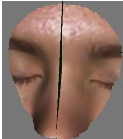
o Plane A –face “frontal” plane ;
o Plane B –face “sagittal” plane that is perpendicular to Plane A. The Plane B divides face into two halves with the best symmetry ;
o Plane C – horizontal plane that is perpendicular to Planes A and B and passes through nose bridge point.
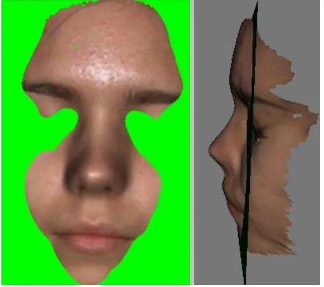
Samples of these planes are shown in Fig.7 and Fig.8.
Figure 7. Anthropometric planes
Figure 8. Anthropometric planes
Differences between distances from inner eye points to planes A, B, C are used as indicators of asymmetry.
Construction of face saggital (or bilateral) plane (and two other planes as well) by anthropometry points is not a perfect solution since few such points are marked and known to system. Error caused by spurious noise and operator mistakes may be large. Better solution is constructing the saggital plane as the one that splits 3D face model into two symmetric parts. Such algorithm has been developed, has been tested and is being used in the system.
5. ALGORITHM OF BILATERAL PLANE AUTOMATIC DETERMINATION
The plane, relative to which the asymmetry of a given 3-D figure is minimal, is called bilateral plane for this figure (Here the figure is set of points in 3-D space). In physical (3D Euclidian) space plane can be set through normal
n
and shiftd
, as a set of points satisfying the equation:
u n
,
d
For an arbitrary point
u
symmetric one relative to the plane isconsidering that the plane’s normal is a unit vector.
Strict bilateral symmetry can be expressed as by-point symmetry, i.e. as a requirement for all points of a figure to be transformed to points also belonging to the figure:
u
u
.To define non-strict bilateral symmetry, we consider a distance from point to figure (i.e. minimal distance from a given point to some point of the figure):
,
min
u
vu
v
And bilateral asymmetry measure (discrepancy of symmetry) is:
,
Then, bilateral surface is the one that minimizes Q.
Face is represented in the system as one-sheet connected finite continuous closed surface. It is also important that this surface is single-valued function specifying dependence of height (distance) from two other coordinates:
Strict bilateral symmetry can be expressed as by-point symmetry, i.e. as a requirement for all points of a figure to be transformed to points also belonging to the figure:
u
u
.
To define non-strict bilateral symmetry, we consider a distance from point to figure (i.e. minimal distance from a given point to some point of the figure):
,
min
u
vu
v
And bilateral asymmetry measure (discrepancy of symmetry) is:
,
Then, bilateral surface is the one that minimizes Q.
Face is represented in the system as one-sheet connected finite continuous closed surface. It is also important that this surface is single-valued function specifying dependence of height (distance) from two other coordinates:
x y where surface is defined, obtaining:
However, it should be taken into account that for some points of reflection there can be no points of surface having same abscissa and ordinate, and vice versa, not all points of original
surface are covered with reflection. For each point
x y
,
from 2D definitional domain
a corresponding point
x y z x y
, ,
,
in 3D exists. For this 3D point its reflection relative to bilateral plane always exists:
defined, and at the region
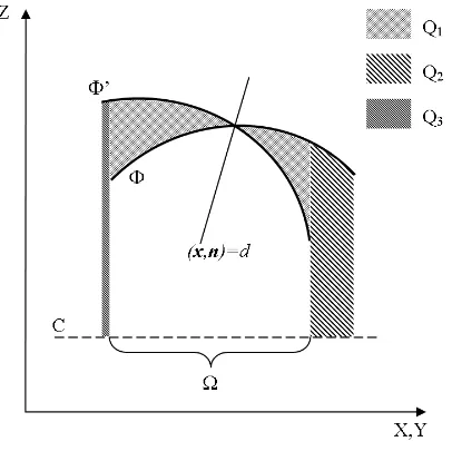
only one of it exists. For this latter case, distance to some plane
z
C
const
is calculated rather than a distance to reflection (See Fig.9).
Figure 9. Distance to a plane.
Then equation (*) may be rewritten as:
Discrepancy depends on parameters of the plane of symmetry:
,
Q
Q
n
d
.In order to diminish it an algorithm of gradient descent or annealing is used. Initial estimate is a plane having normal vector parallel to OX axis and passing through nose bridge point (this point is set during previous steps of processing). It is also possible to use direct looking through region of parameters in some area around initial estimate with a given step.
Face surface in the system is represented as triangulation that is a mesh of 3D points and a set or triples of these points (triangles). Aggregate of these triangles is a one-sheet connected finite continuous closed surface. There are two ways of practical estimation of the quality for surface represented in this way:
Numerical integration at the grid of points with constant step, which is chosen in way that every mesh triangle fits at least one point.
Building aggregate triangulation of original and reflected surfaces (Dishkant N., 2008).
In the version of system under consideration first approach is used, which is algorithmically simpler but requires larger calculation amount for satisfactory precision.
Parameters
n
,
d
determining optimal plane location can be found by minimizing the discrepancy
,
Q
Q
n
d
For further estimates we propose that this asymmetry minimum is a true bilateral face asymmetry measure.
Method of location of saggital face plane optimal position and estimation of asymmetry of face anthropometric points relative to this plane is described below.
6. AUTOMATIC SEARCH OF OPTIMAL PLANES
Sagittal plane is searched with a subset of facial surface points lying inside specified sphere. The sphere has its center at the nose bridge point, and radius of the sphere is approximately equal to distance from nose bridge to eye center. Radius of the sphere is estimated as average value of distances from nose bridge to right and left inner and outer eye corners. All possible planes close to OYZ planes are looked over.
Plane is set by directing vector (for OYZ plane the directing vector is OX basic vector) that varies in range from -15 to +15 degrees along OY and OX axes with 21 steps along each (1.5 degrees per step). Asymmetry value of points included in the sphere is calculated at every step.
Asymmetry value is proportional to sum of absolute values of point. Sample of plane constructed by the algorithm is depicted in Fig.10
Figure 10. Sample of plane constructed by the algorithm
7. RESULTS OF FACE ASYMMETRY MEASUREMENTS
Face 3D models of 78 persons have been constructed and investigated during the research period.
Simultaneously these persons were examined by qualified ophthalmologist. The medical diagnosis was presented conventionally in the numerical form as the parameter that could be varied in the range from 0 to 10, depending on presence of vision pathology.
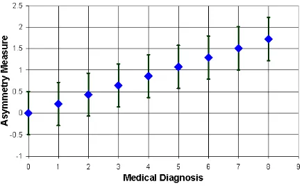
After that, the face models were processed according to the method described above. Asymmetry estimations were done for the plane A (frontal plane), constructed after automatic determination of bilateral plane B by the algorithm described above. Three different sets of anthropometric points were used for asymmetry estimations and the resulting asymmetry measure was calculated by averaging these estimations. Linear regression between asymmetry measure and medical diagnosis was plotted. The sample of such plot is shown in Fig.11.
Figure 11. Asymmetry measure vs medical diagnosis
The results presented obviously demonstrate the possibility of evaluation of human vision pathology diagnosis by measuring face asymmetry on 3D face model and using the functional dependence obtained. However, for achieving more precise evaluation of this functional dependence, further experimental research is required with participation of larger number of patients with different face pathologies.
8. CONCLUSIONS
A technique for human vision pathology diagnostics using photogrammetric approach is proposed. It is based on patient face 3D model analysis for detecting face asymmetry as a possible reason human stereoscopic vision capability dysfunction.
Photogrammetric system for human face 3D model acquisition is used. It provides fast 3D model acquisition and high accuracy needed for asymmetry analysis. Experimental study performed for 78 patients demonstrates the possibility of evaluation of human vision pathology diagnosis by measuring face asymmetry on 3D face model and using the functional dependence obtained.
9. REFERENCES
1. Knyaz V.A., Krychenkov V.F., Matveev I.A., Murynin A.B., 2007. Studying correlations between face asymmetries and vision pathologies by methods of 3D modeling. Proceedings of ISA RAS. Dynamics of nonuniform, 2007, V. 29(1), p.223-229 (in Russian)
2. Knyaz V.A., Zheltov S.Yu., 2000. Approach to Accurate Photorealistic Model Generation for Complex 3D Objects. International Archives of Photogrammetry and Remote Sensing. 2000. V. 33. Part B5/1. P. 428-433
3. Knyaz V.A., 2005. Photogrammetric Technique for Accurate Human Body 3D Reconstruction. Proceedings of 15th International Conference on Computer Graphics and
Applications, Graphicon’2005, Novosibirsk, June 20-24, 2005, pp. 297-300.
4. Krychenkov V.F., Matveev I.A., Murynin A.B. et al, 2001. Estimation of Bilateral Facial Symmetry Deviation Using a Sterioscopic Computer Vision System. Pattern Recognition and Image Analysis. 2001. V.11. № 2. P. 350-352.
5. Dishkant N., Mestetcki L., 2008. Comparison of Surfaces Obtained by 3D Scanning. // Graphicon’08, Moscow, June 23-27, 2008
6. Murynin A. B., Matveev I. A., 1998. 3-D Surface Reconstruction in Automatic Recognition System . SPIE, Vol. 3516 , 1998
7. Marr D., Poggio T., 1979. A Computational Theory of Human Stereo-vision. Proceedings. Royal Society. London, 1979, V.B204
8. Fua P., 1993. Parallel stereo algorithm that produces dense
depth maps and preserves image features”. Machine Vision and Applications, 1993, V.6