CALIBRATION OF A MULTIPLE STEREO AND RGB-D CAMERA SYSTEM FOR 3D
HUMAN TRACKING
Konstantinos Amplianitis, Michele Adduci and Ralf Reulke∗ Humboldt Universit¨at zu Berlin
Computer Science Department, Computer Vision Rudower Chaussee 25, 12489 Berlin, Germany
(konstantinos.amplianitis, michele.adduci, reulke)@informatik.hu-berlin.de
KEY WORDS:Multi Camera System, Bundle Adjustment, 3D Similarity Transformation, 3D Fused Human Cloud
ABSTRACT:
Human Tracking in Computer Vision is a very active up-going research area. Previous works analyze this topic by applying algorithms and features extraction in 2D, while 3D tracking is quite an unexplored filed, especially concerning multi–camera systems. Our approach discussed in this paper is focused on the detection and tracking of human postures using multiple RGB–D data together with stereo cameras. We use low–cost devices, such as Microsoft Kinect and a people counter, based on a stereo system. The novelty of our technique concerns the synchronization of multiple devices and the determination of their exterior and relative orientation in space, based on a common world coordinate system. Furthermore, this is used for applying Bundle Adjustment to obtain a unique 3D scene, which is then used as a starting point for the detection and tracking of humans and extract significant metrics from the datasets acquired. In this article, the approaches are described for the determination of the exterior and absolute orientation. Subsequently, it is shown how a common point cloud is formed. Finally, some results for object detection and tracking, based on 3D point clouds, are presented.
1 INTRODUCTION
1.1 Motivation
Video monitoring is an important part in ensuring safety and se-curity of public transportation systems. Automation using image and signal processing methods allows improving the efficiency and reliability of such systems. Current developments of video surveillance systems allow automatic detection and tracking of people. The analysis of movement patterns may enable to im-prove the safety in public transport systems. This development is part of a project that involves the conception and implemen-tation of a real-time tracking system. A brief overview can be found in (J¨urgensohn, 2013). This work refers to the observation of the behaviour of people in waggons of local public transporta-tion (U-Bahn or S-Bahn). The aim is the recognitransporta-tion of atypical or dangerous situations from the derived trajectories. A possible approach to the situation description can be found for example in (Reulke et al., 2008).
Indoor object recognition provides a number of challenges:
• Few cameras and thus a large field of view for a camera
• Occlusions by passengers as well as seats and handrails in the wagon
• Drastic changes in brightness within the scene e.g. windows and shaded regions and between the recorded images (tun-nel, sunny areas)
• Areas in which image processing provides erroneous results (windows, TV monitors)
This results in a specific approach regarding the cameras and image processing (occlusion–free) monitoring of the passenger compartment:
∗Corresponding author
• Full 3D capture of the observed space by point clouds (ad-vantages lie here in the background estimation, dealing with the shadow of and with guards)
• Use of multi–camera systems to avoid occlusions conditions. Derivation of 3D information by stereo cameras and RGB– D systems with large field of view, fast matching and 3D point cloud handling
• Determination of the 3D background
• Detection of separate objects (that stand out from the 3D background)
• Mathematical description of 3D objects by distinctive 3D points and 3D structures (e.g. boxes and ellipsoids)
• Derivation of relevant attributes from the individual camera views
• Tracking and fusion of the different views on an abstract representation of the occupancy of the passenger compart-ment
• Situation analysis from the trajectories
Calibration or interior or exterior orientation determination of all cameras, enables the system to process the input video from different views depending on the camera position and the scene characteristics. In addition to the synchronization of all systems and the orientation determination is an important prerequisite. In complex observation situations there exists extended occlusions, shadows and / or rejections, so that an appropriate calibration is required in order to achieve a highly developed people segmen-tation as well as a tracking algorithm. In the majority of cases, once the system has been installed in a certain scene, it is difficult to obtain the calibration information of the scene.
1.2 Related Work
The investigations in (Hegger et al., 2013) is related to human-robot-interaction. The detection of peoples in domestic and un-constrained environments is crucial for a service robot. People detection is based on data from a RGB-D camera. They introduce a 3D feature descriptor based on Local Surface Normals (LSN). (Luber et al., 2011) investigates people tracking in robot develop-ment. They present a 3D people detection and tracking approach using RGB-D data by combining a multi-cue person detector with an on-line detector that learns individual target models. The work of (Spinello et al., 2011) is related to (Luber et al., 2011). Here the focus is here the bottom-up detector, which learns a layered person model from a bank of specialized classifiers for differ-ent height levels of people that collectively vote into a continu-ous space. (Song and Xiao, 2013) construct a unified benchmark dataset of 100 RGB–D videos with high diversity, propose differ-ent kinds of RGB–D tracking algorithms using 2D or 3D model, and present a quantitative comparison of various algorithms with RGB or RGB–D input.
2 APPROACH
We introduce a multi–camera system using low–cost sensors like stereo cameras and Microsoft Kinect devices for detecting and tracking people in a 3D point cloud. The complete pipeline, start-ing from the acquisition of the point clouds, the extraction of the moving human bodies and their registration / fusion in a georef-erenced system is explained in the form of pseudo code in Algo-rithm 1.
At first, raw point clouds had to be acquired simultaneously from all sensors. Then, using RGB images captured by the Kinect sen-sors or equivalent gray scale 8 bit images from the stereo cameras, we were able to retrieve their exterior orientation (position and di-rection) with respect to a local chessboard coordinate system. By empirically defining some ground control points in the final geo-reference or parent coordinate system and computing their coor-dinates from spatial resection in the chessboard system, we were able to transform all from their local system, to the chessboard system and finally in the georeference system.
The rest of the algorithmic pipeline contains a number of steps which are important for extracting the moving foreground object. It is well known that point clouds, depending on their density and scene complexity are meant to be very difficult and time consum-ing to process. Algorithms developed for organized point clouds produced for example by stereo cameras, Kinect sensor or TOF cameras are meant to work much better then unorganized clouds (e.g. produced by a range sensor or laser scanner). In every case, it is important to undertake some preprocessing steps for remov-ing un-useful information and therefore reducremov-ing the amount of 3D points for processing. As a result, algorithms developed for extracting moving objects will have to process on fewer points. We start by removing all unnecessary 3D values and trimming the rest of the point cloud in the depth direction reducing then the FOV of the sensor. We continue with the detection of moving ob-jects in the scene, by comparing the octree structures of an empty static background and the current point cloud using a bitwise log-ical approach. If moving objects exist, then the foreground points are projected on a 2D plane for checking and maintaining these points that are grouped within a large contour and removing the ones that are not.
All 3D points corresponding to these large contours are said to be moving objects and not noise. Moreover, applying all the aforementioned procedures in the rest of the point clouds corre-sponding to the same time stamp, two sequential transformations
clouds can be applied. The first one transforms the foreground point cloud from its local coordinate system defined by the sen-sor to the chessboard coordinate system and the second one from the chessboard system to the world coordinate system defined by another set of infrared cameras (georeference system). In the up-coming sections, a more extended description of the processing pipeline will be made.
Algorithm 1Extraction and fusion of foregrounds with synchro-nized cameras
Require: Point cloud from each sensor
1: Apply Bundle Adjustment to retrieve the projection camera matrices of the sensors with respect to the chessboard coor-dinate system.
2: Derive the 3D similarity transformation parameters between the chessboard system and the ARTracker system (georefer-ence system) using common target points.
3: for allpoints of the clouds acquired simultaneouslydo 4: Remove NaN values
5: Trim point cloud
6: Extract moving foreground (Humans) 7: ifforegrounds exist then
8: Project foreground to a 2D plane 9: Extract closed contours (blobs)
10: ifsize of blob larger then a predefined thresholdthen 11: Retain 3D points corresponding to these blobs 12: Downsample foregrounds
13: Transform to chessboard coordinate system 14: Transform to Global Coordinate System (ARTracker) 15: end if
16: end if 17: end for
18: return Fused foreground point clouds
2.1 Sensor Synchronization
Acquiring data from many devices simultaneously is not a trivial task, because of hardware latency. Microsoft Kinect sensors use a USB connection and require a dedicated bus due to the high rate of information generated from both depth and RGB cameras: this means that only one device per USB bus can be connected. The use of multiple buses introduces a small hardware latency, which in our hardware configuration corresponds to roughly 16 ms. As a result, acquired data tend to get influenced and could also con-tain potentially unusable information, due to the time mismatch. To get rid of this latency and retrieve images simultaneously, we use a multithread approach and a timer larger than the hardware latency time, to trigger the acquisition of each image from Kinect. Once the acquisition of a frame is completed from all the devices driven by threads, a new signal is triggered and the acquisition continues. In the case of people counter devices (stereo cam-eras), we encountered the same problem: these stereo cameras are connected through Firewire to multiple Firewire cards and the hardware latency is in the range of 32ms. The usage of a timer decreases the potential maximum framerate available, preserving data consistency: for Kinect we obtain a frame rate of 19fps using four devices and for the stereo cameras we achieve a rate of ap-proximately 14fps using 6 devices simultaneously. The data rate generated from both MS Kinect and stereo cameras is around 1 MByte / frame per device, forcing us to use an SSD drive to speed up the storage performance time.
2.2 Bundle Adjustment
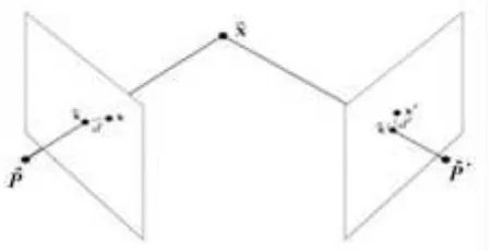
intersecting in space. The problem that occurs from the intersec-tion of rays in space is that they dont meet at an optimal point (best intersection of the corresponding rays). Thus, bundle ad-justment deals with the re arrangement of the camera positions and 3D points, to achieve having an optimal intersection of the rays in 3D space. In practice, that is interpret by trying to min-imize the distance between the measured points on the images and the ones that are back projected from the rearrangement of the cameras and reconstructed points (Figure 1 from (Hartley and Zisserman, 2004)). This is mathematically expressed as:
min
wherexijis the image pointjon imagei, is the 3x4 projection camera matrix (explained at a later point) corresponding to the
ithimage andXˆjis the corresponding 3D point.
Figure 1: The reprojection error
A very well known algorithm for solving non linear equations is the Levenberg Marquard algorithm that uses a damping approach for converging promptly from any initial value given. Though the mathematics around bundle adjustment are quite frastrasted for first site readers especially without any prior knowledge in the mathematical model, we will try and simplify the formulation and adapt it to our current camera setup.
Due to the different amount of cameras per type (eg. Microsoft Kinect, stereo cameras, etc.) we will define a more generic for-mulation that is easily adaptable to any group of cameras. Let
f(p)be a function that relates a parameter vectorp, with an es-timated measurement vectorxˆ =f(p),xˆ ∈ ℜ2. The estimated measurement vector contains the corrected image points defined from the optimization of the bundle of arrays andf(p)is a func-tion that has as arguments ofpthe parameters of the cameras and the 3D points. Thereforepis of the form:
p= [P1, P2, ..., Pn, X1, X2, ..., Xm] (2)
wherenis the number of cameras,mthe number of 3D points,
Xithe 3D homogeneous points andPiis the 3x4 projection cam-era matrix defined as:
As seen from Eq. 3, the projection camera matrix can be decom-posed in four sub–matrices:
The first matrix on the left of Eq. 4 is called calibration matrix and it contains the internal (in photogrammetric terminology) or intrinsic (in computer vision terminology) parameters of the cam-era, wherefx, fyare the principal distances of the sensor andx0,
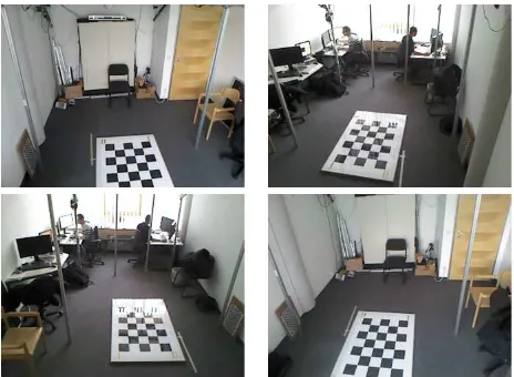
y0is the position of the principal point from the projection center to the sensor. Matrix R is a 3x3 rotation matrix which describes the orientation of each of the axes X, Y and Z of the camera with respect to a global coordinate system and vector C contains the position of the camera in space with respect to a global coordi-nate system. An initial parameter vector p0 and measurement vector x (observed image points) are required for finding a vec-tor that best satisfies the functional relation, meaning finding the values of this vector that will locally minimize the objective func-tion. A stopping criterion used, is that the error between the ob-served and calculated values has to be minimised (Eq. 1). At this point, the only difference between the initial parameter vec-tor used for Kinect sensors and for stereo cameras is limited to the fact that the calibration matrix K is fixed for Kinect and for the stereo cameras not. Therefore after bundle adjustment, the calibration matrices for all Kinects will remain unchanged but for stereo cameras it will be refined. Bundle adjustment will be done based on a chessboard coordinate system as seen in Figure 2. Artificial 3D ground control points will be generated along the chessboard corners based on the size of the pattern, its rows and columns. As a result these 3D points will be used in the ini-tial parameter vector. For the measurement vector, points where manually clicked due to occlusion problems in some of the cor-ners (glassy effect). Keep in mind that every chessboard corner a unique ID has been assigned and therefore in the clicking process every clicked point will have to be to be given the ID it refers too in 3D space. This is crucial for the triangulation step later on in the bundle adjustment process. Mismatched IDs will fail inter-secting corresponding rays in space coming from corresponding homologous points on the image and so bundle adjustment will be terminated unsuccessfully. Finally, after having all the data re-quired, the augmented normal equation is solved in a non linear manner until Eq. 5 is satisfied:
JTJ+µIδP =J εp (5)
whereIan identity matrix,µ·Iis known as damping,µis the damping term,Jis the Jacobian matrix defined asJ=∂ff((pp)),δp is the corrected measurement vector andǫpis the error between the observed and calculated measurement vectorsx−xˆ. For fur-ther understanding of the bundle adjustment approach the reader should refer to (Agarwal et al., 2010).
2.3 Removal of NaN values and Point Cloud Trimming
Figure 2: Chessboard pattern seen from four Kinects
second preprocessing step, where un-useful points in the back-ground, not part of the active FOV, can be removed. Therefore we trim the point cloud in the Z (depth) direction of the sensor using a predefined threshold set manually by the user. We con-sidered trimming points which are not (in depth) part of the FOV.
2.4 Object Detection
For detecting moving objects (in this case human), a static or adaptive in time background is needed for comparing the cur-rent frame with it. Thus, any kind of changes in the background which are not known in the current frame can be considered as foreground. This is how in principal 2D foreground estimation works. In 3D, a different kind of procedure is needed because of the way point clouds behave in time. We used a method intro-duced by Kammerl, et al. in (Kammerl et al., n.d.), who tried to model the spatial relation of 3D points with their adjacent points using an octree representation. An octree is a tree based data structure in which each internal/leaf node has exactly eight chil-dren. Each node in the octree subdivides the space it represents into eight octans. In the case of object detection it can be used by detecting spatial changes between the octrees of the background and current cloud. Spatial changes in the leaf node of the tree (sparsity of points, amount of neighbours etc.) can give us an indication of spatial changes. Depending on the predefined size of the leaf node, detection sensitivity rate and processing time can vary. Large leaf nodes are faster to process but dont provide detailed information on the foreground and therefore only very significant spatial changes are detected. On the contrary, very small leaf sizes can capture detailed spatial changes but the com-putation time is extremely costly. In all cases, based on the FOV and amount of detection required, leaf size can be adapted manu-ally by the user. For more information refer to the authors paper (Kammerl et al., n.d.).
2.5 Projection on a 2D Plane
Detecting moving objects in the point cloud does not mean that noisy regions (also detected as foregrounds), far away or close to the moving objects cannot be present. This is a typical problem seen in 2D foreground estimation but in 3D, depending on the sensor used, noise might have a different generation form. Plac-ing multiple Kinect sensors lookPlac-ing at each other will create a conflict of their infrared beams and so the generated point clouds will be extremely noisy. Therefore we orient the sensors towards the ground of the scene in order to reduce having these kinds of problems. On the contrary, noise present in point clouds gener-ated from stereo cameras, is a result of bad rectification, point
matching and disparity map computation. Homogeneous areas (eg. walls) tend be very noisy in the generated point cloud and thats a result of bad point matching. We approach the problem by projecting all foreground points on a 2D plane using the calibra-tion informacalibra-tion of our cameras:
x=fx
X
Z +x0 y=fy
Y
Z +y0 (6)
wherex,yare the image coordinates,fx,fyrepresent the focal length of the camera in pixels in thexandydimensions respec-tively,x0,y0 is the principal point of the sensor andX, Y,Z are the coordinates in 3D space. Subsequently, having this binary image, connected components analysis was applied for extract-ing all 2D contours. Areas which are larger than a predefined threshold are retained and the rest are removed. In this way, what is considered as a moving object and not moving noise is more controlled.
2.6 Down-sampling Foreground
Deducing meaningful geometrical information from an articu-lated moving object does not require all points of the object to be present. Therefore, the foregrounds was down-sampled using a voxel based grid filter. By definition, voxel grid filter breaks down the 3D scene in 3D voxels (3D boxes in space). Within each voxel, a mean point is computed taking into account all points within the box. As a result, a down-sampled point cloud is created which can retain its underlying geometry quite accurately (if a good voxel size is given). The amount of down-sampling is a crucial issue. Very large voxels may completely remove the geometry that wish to maintain. There were two other things: at which point in the algorithm should be applied the downs-ampling and in which amount. For the first part, we decided to apply it after extracting the foreground object in order to avoid downsampling the full point cloud. Therefore in this way we sig-nificantly speeded up the complete algorithmic process. Also, another reason is that connected component analysis cannot be applied on projected points which are not dense enough on the binary image. Concerning the second part, downsampling rate is important in case you wish to make use of your foreground objects for extracting meaningful geometry from them or if you want to apply ICP algorithm to stitch your foregrounds.
2.7 Fusion of Foregrounds
whereX,Y,Z andX′,Y′,Z′are the initial and transformed 3D Euclidean coordinates respectively,λis a scalar value repre-senting global scaling,Ris a 3D rotation matrix andT is a 3D translation vector. For computing the transformation parameters, more than 3 common points are required in principal. That is be-cause there are 7 unknowns (3 rotations, 3 translations and one global scaling). Lets start by defining a vectorF containing all foregroundsCifrom all cameras at timet:
Ft= [C1, . . . , CN], Ci∈ ℜ3 (8)
where N is the total number of cameras. Using the rotation and translation parameters extracted directly from the projection cam-era matrix of each Kinect or Hella stereo camcam-eras we were able to build a3×4transformation matrix that will transform the in-dividual foregrounds to the chessboard coordinate system:
XChessi=Ti·Cii= 1, . . . , N (9)
whereTiis a3×4transformation matrix of the current camerai,
Ciis a data set containing the current foreground points of cam-eraiandXChessi are the transformed points in the chessboard coordinate system. Finally, the transformation from the chess-board system to the georeference system is expressed by:
XARi =H·XChessii= 1, . . . , N (10)
whereHis a 3D similarity transformation,XChessi are the 3D points in the chessboard coordinate system and XARi are the transformed 3D points. For estimating the quality of the 3D sim-ilarity transformation the following formulation was used:
err=
N
X
i=1
kXT riangi−XGCPik 2
(11)
whereerris the square distance error between all points in the two datasets expressed in meters, XT riang represents the 3D points transformed from the chessboard system to the ARTracker system andXGCP are the GCPs defined in the ARTracker sys-tem.
3 EXPERIMENTAL RESULTS
3.1 Camera Setup
Our experimental setup consists of four Microsoft Kinect sen-sors, six stereo cameras and four infrared cameras. All cameras are mounted on a constructed aluminium platform as seen in Fig-ure 3. Light orange colour is used for visualizing the position of the Kinect sensors, green for the stereo cameras and yellow for the position of the ARTracker infrared cameras. Kinect sensors and stereo cameras are placed in approximately 2.3m high and the infrared sensors around 2.5m, directly at the most highest cor-ners of the construction. Due to intersection of the infrared light emitted from the Kinects, the sensors where not looking directly to eachother but were tilted towards the ground. With this way we tried to avoid introducing unnecessary noise in the generated point cloud.
Figure 3: Camera setup
3.2 Cameras Characteristics and Hardware
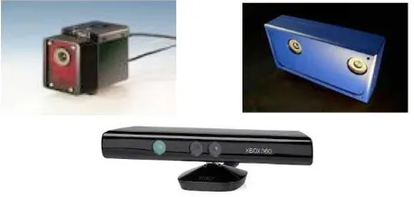
Kinect sensors looks like a horizontal elongated bar connected on a base with a motorized pivot and consist of an infrared emitter, RGB camera sensor, depth sensor and a multi microphone sys-tem. The emitter emits infrared light towards the 3D scene and the depth sensor receives the infrared beams reflected back from the objects, which is then used to generate the depth image. The resolution of the RGB and depth images is640×480pixels and so the generated point cloud has an organized form of 307200 points. Their practical depth working limit without introducing artifacts is within the range of 1.2 and 3.5 meters. For the stereo cameras provided by Hella Aglaia Mobile Vision GmbH, each device contains two cameras with a baseline of 8cm. The sensor has769×448pixel, produces 12 bit gray scale images and has a repetition rate of approximately 10 Hz. The ARTracker are op-tical tracking cameras and work with passive or active markers which look like in Figure 5. They contain an integrated pattern recognition unit which is used for detecting and tracking these markers in time. Working distance using passive markers is up to 4.5 m depending also from the size of the markers and the frame rate reaches up to 60 fps. All devices used can be visualized in Figure 4. On the upper left image we show the ARTrack infrared camera, upper right the Hella stereo camera and in the bottom the Microsoft Kinect sensor.
Figure 4: All camera devices used
Figure 5: Target balls used for tracking
3.3 Bundle Adjustment and 3D Similarity Transformation
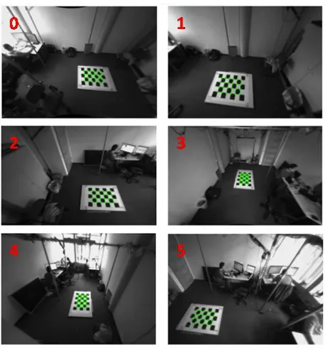
Using the chessboard as a reference system for all Kinect and Hella cameras we empirically defined one of the chessboard cor-ners to be the origin of the 3D coordinate system. By manually clicking at the corners of the visible chessboard we were able to define the observation vectors needed to solve the bundle adjust-ment as described in section 2.2. In Figure 6 and 7 you can visual-ize the corrected points (green color) of the observed chessboard corners coming from all four Kinect sensors and Hella cameras after refining their projection camera matrices.
Several corner detectors are available from open source libraries (eg. OpenCV) for automatically detecting and refining with sub-pixel accuracy the detected corners. In our case, these algorithms would fail: occluded pattern in some of the images, glassy effect and also bad perspective viewing angles are one of the main prob-lems we had to deal with. The RMS error for the Kinect sensors was in the range of approxinately quarter of a pixel (∼0.25 pix) where as for Hella cameras in the range of a sub pixel (∼0.5 pix). It is known that the result of the bundle adjustment is significantly affected by the quality (accuracy) of the measurement points. As seen from table 2 there exist an RMS value for camera 3 which is in the range of∼2.4 pix. This is because of the bad viewing direction of the pattern which does not help to generate a good measurement vector for the current image.
Kinect sensors reprojection error (pix)
Camera ID 0 1 2 3
RMS 0.26 0.26 0.28 0.26
Table 1: Kinect bundle adjustment results
Hella cameras reprojection error (pix)
Camera ID 0 1 2 3 4 5
RMS 0.55 0.23 0.33 2.41 0.60 0.36
Table 2: Hella bundle adjustment results
Figure 6: Corrected chessboard points after applying bundle ad-justment to all four Kinect sensors
Figure 7: Corrected chessboard points after applying bundle ad-justment to all six stereo cameras
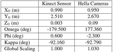
Next step involves finding the similarity transformation param-eters (three rotations, three translations and a global scaling) for transforming the foreground point clouds from the chessboard co-ordinate system to the ARTracker georeferenced coco-ordinate sys-tem. For this purpose, as mentioned in section 2.7, common tar-get points are needed in both systems. We followed the procedure of placing four tripods in the middle of the common FOV of all cameras (Kinect and Hella stereo cameras) in different heights and placing the tracking balls on top of a horizontal platform. In Figure 8 you can visualize/recognise the common targets with a red dot.
Figure 8: Common target points as seen from all four Kinect sen-sors
Kinect Sensor Hella Cameras
X0(m) 0.990 0.950
Y0(m) 2.510 2.670
Z0(m) 0.003 0.09
Omega (deg) -179.500 177.360
Phi (deg) 0.600 -2.300
Kappa (deg) -92.160 -92.790
Global Scaling 1.000 1.030
Table 3: Similarity transformation parameters for Kinect Sensors and Hella Cameras
One thing which is interesting in the above results is the mirroring effect in the omega angle between the two systems. Omega angle is a rotation around the X axis which after some testing does not create a problem to the sequence of the transformation (Z - Y - X and finally translation). In either cases, a rotation of plus minus 180 degrees brings the system in the same orientation and position as the georeferencing one.
3.4 Object Detection
This experimental part contains results from human detection in a point cloud. In Figure 9 there is a result from a fused foreground of a human figure acquired from all four Kinect devices.
Figure 9: Fused point clouds from all Kinect sensors
In Figure 10 you can visualize a stitched point cloud with the people in the scene being quite in one piece without any kind of duplications. Keep in mind that this point cloud is not stitched using ICP (Iterative Closest Point) algorithm but only using the sequence of transformations mentioned in steps 13 and 15 of al-gorithm 1. This shows that the resultant point cloud is strongly dependent from the accuracy of the projection camera matrices coming from the bundle adjustment and subsequently from the accuracy of the triangulated coordinates of the targets and not necessarily from a good initial transformation matrix required for ICP. In this way we show that the run time performance of our approach is much faster than doing the fusion using ICP. There might be a possibility that ICP might be needed if the RMS error of cameras coming from bundle adjustment is not very good. Fur-thermore, we show that camera synchronization is very important for stitching the same figures coming from different point of view. Especially in human tracking, where the movement has an artic-ulated form, non exact synchronization of the sensors by some ms would create an error propagation which after some frames might be converted into seconds. This will automatically show (most probably) small differences in the articulated movement of the human and will start producing foreground point clouds with the amount of propagation translated in motion difference.
Figure 10: Stitched point cloud coming from all four Kinect sen-sors
Finally, in Figure 11we show a fused point cloud coming from all six Hella stereo cameras. Again, as you can see from the person in the scene, his body is into one piece without any repetitions.
Figure 11: Fused point clouds coming from Hella stereo cameras
4 CONCLUSIONS AND DISCUSSIONS
of individual objects which should be treated as independent en-tities while they are tracked. A lot of work is been done on multi camera systems in 2D and so we believe that equivalent 3D ap-proached should be investigated. Finally, we could consider ac-celerating our algorithms by reducing their time complexity using GPU programming.
5 ACKNOWLEDGEMENTS
We would like to thank Hella Aglaia Mobile Vision GmbH for providing 10 stereo cameras within the project SecuRail, for ac-quiring data and testing algorithms.
REFERENCES
Agarwal, S., Snavely, N., Seitz, S. and Szeliski, R., 2010. Bundle adjustment in the large. In: K. Daniilidis, P. Maragos and N. Para-gios (eds), Computer Vision ECCV 2010, Lecture Notes in Com-puter Science, Vol. 6312, Springer Berlin Heidelberg, pp. 29–42.
Hartley, R. I. and Zisserman, A., 2004. Multiple View Geometry in Computer Vision. Second edn, Cambridge University Press, ISBN: 0521540518.
Hegger, F., Hochgeschwender, N., Kraetzschmar, G. and Ploeger, P., 2013. People Detection in 3d Point Clouds Using Local Sur-face Normals. Lecture Notes in Computer Science, Vol. 7500, Springer Berlin Heidelberg, book section 15, pp. 154–165.
J¨urgensohn, T., 2013. Videokameras in bus und bahn, automatis-che bildauswertung in der entwicklung. SIGNAL, GVE-Verlag.
Kammerl, J., Blodow, N., Rusu, R. B., Gedikli, S., Beetz, M. and Steinbach, E., n.d. Real-time compression of point cloud streams. In: Robotics and Automation (ICRA), 2012 IEEE International Conference on, pp. 778–785.
Luber, M., Spinello, L. and Arras, K. O., 2011. People tracking in rgb-d data with on-line boosted target models. In: Proc. of the IEEE/RSJ Int. Conf. on Intelligent Robots and Systems (IROS), San Francisco, USA.
Reulke, R., Meysel, F. and Bauer, S., 2008. Situation Analysis and Atypical Event Detection with Multiple Cameras and Multi-Object Tracking. Lecture Notes in Computer Science, Vol. 4931, Springer Berlin / Heidelberg, pp. 234–247.
Song, S. and Xiao, J., 2013. Tracking revisited using rgbd cam-era: Unified benchmark and baselines. In: 14th IEEE Interna-tional Conference on Computer Vision (ICCV2013).