OBLIQUE AERIAL PHOTOGRAPHY TOOL
FOR BUILDING INSPECTION AND DAMAGE ASSESSMENT
A. M urtiyoso1, F. Remondino2, E. Rupnik2, F. Nex2, P. Grussenmeyer1
1
INSA Strasbourg / ICube Laboratory, France
Email: (arnadi.murtiyoso, pierre.grussenmeyer)@insa-strasbourg.fr
2 3D Optical M etrology Unit, Bruno Kessler Foundation, Trento, Italy Email: (remondino, rupnik, franex)@fbk.eu, Web: http://3dom.fbk.eu
KEYWORDS : monoplotting, oblique imagery, measurement, façade inspection, disaster assessment
ABS TRACT:
Aerial photography has a long history of being employed for mapping purposes due to some of its main advantages, including large area imaging from above and minimization of field work. Since few years multi-camera aerial systems are becoming a practical sensor technology across a growing geospatial market, as complementary to the traditional vertical views. M ulti-camera aerial systems capture not only the conventional nadir views, but also tilted images at the same time. In this p aper, a particular use of such imagery in the field of building inspection as well as disaster assessment is addressed. The main idea is to inspect a building from four cardinal directions by using monoplotting functionalities. The developed application allows to measure building height and distances and to digitize man-made structures, creating 3D surfaces and building models. The realized GUI is capable of identifying a building from several oblique points of views, as well as calculates the approximate height of buildings, ground distances and basic vectorization. The geometric accuracy of the results remains a function of several parameters, namely image resolution, quality of available parameters (DEM , calibration and orientation values), user expertise and measuring capability .
1. INTRODUCTION
Photogrammetry has been a standard tool for large and medium scale mappings. It provides for planimetric as well as altimetric data of the imaged area and eventually its radiometric properties within an orthophoto. Nowadays, with the rise of UAVs / RPAS (Unmanned Aerial Vehicles / Remotely Piloted Aircraft Systems) and low-cost cameras, p hotogrammetry could also deliver small scale mapping (depending on national flight regulations). UAV platforms (Colomina and M olina, 2014; Nex and Remondino, 2013) have indeed proved to be a versatile and useful tool in fast response jobs - such as during/after a disaster - with the main objective of creating an up -to-date picture of the situation in a short period of time. However when it comes to large and complex scenarios, airborne acquisitions with medium- and large-format aerial cameras, maybe combining vertical and slant views, are still much more powerful and reliable, in particular for building façade inspections. In this regard, oblique images can provide faster measurements and reliable mapping outcomes (Höhle, 2008).
The idea of aerial oblique photography goes back to the origin of photogrammetry but just recently oblique imagery is a rediscovered technology, considered in the photogrammetric community as one of the major developments in the field and a great source of geo-information. In an multi-camera systems, a nadir camera is pointing downwards as in conventional photogrammetric acquisitions whereas the other cameras are tilted to a certain degree as to picture the scene in a slanted view (Gerke et al., 2014; Jacobsen, 2008). Nowadays there exists several commercial systems able to deliver oblique aerial imagery, normally classified as (Rupnik et al., 2014):
1. Fan configuration, with twin cameras which extend the cross-track ground coverage (examples: Trimble AIC x2 or Dual DigiCAM );
2. M altese cross configuration, with one single nadir camera and four cameras tilted towards cardinal directions (examples: IGI, Midas TRACK’ AIR, Leica);
3. Block configuration (examples: Trimble AIC x4 and IGI DigiCam Quattro).
The actual interest in oblique photography for mapping purposes is due to its primary quality: the disclosure of the entire building’s façade and, normally, its footprints. The applications based on oblique aerial views are multiple: dense point clouds extraction for 3D city modelling (Fritsch and Rothermel, 2013), building detection and reconstruction (Nex et al., 2013), urban area classifications (Gerke and Xiao, 2013), building structural damage identification (Nyaruhuma et al., 2012), etc.
According to the on-going EuroSDR questionnaire1 outcomes (Gerke and Remondino, 2014), the two main properties of oblique aerial imagery are the easier object identification and the increase reliability whereas the major applications are visualization, dense image matching, textured 3D city models. Following this interest and potentialities, t he main aim of the paper is to review the monoplotting functionality and implement a monoplotting tool for multi-camera aerial systems. The tool could be used to quickly assess man-made structures for inspection, cadaster issues, measurements, modeling and visualization purposes.
The datasets used for experimental tests are oblique and nadir images acquired with a modified M idas5 system called BlomOblique (5 Canon EO S 5D M ark II cameras). Two datasets were used: one over the city of M ilan (Italy) and a second one over the town of San Felice sul Panaro (Italy) which was hit by an earthquake in M ay 2012.
2. THE MONOPLOTTING TOOL
2.1 Overview
M onoplotting refers to a photogrammetric method where a single image (oblique or vertical, terrestrial or aerial) is linked to the Digital Elevation M odels (DEM ) of the corresponding imaged scene (Sheng, 2005; Kraus, 2007; Bozzini et al., 2012). The intersection between the DEM and the collinearity ray from the camera will be the object’s position in 3D space. This
1
is unlike the more common stereo-photogrammetry where we intersect the rays emitted from two or more cameras to determine this position (Fig. 1). M onoplotting is useful, for example when we need to quickly measure points and extract information from a single photo.
Figure 1. Principles of stereo and mono photogrammetry
2.2 Tool functionalities
The developed tool implements the main monoplotting functionalities to perform measurements from single oriented images, given known height values of the area of interest. The tool accommodates any datasets of aerial images acquired with a multi-camera system and it consists of two parts:
1. the main collinearity and back-projection algorithms used in the point selection and building façade identification function; 2. measurement functions which allows the user to calculate building heights, digitize surfaces or retrieve any other quantitative and metric information.
2.2.1 Collinearity and back-projection
The backbone of the method is the collinearity condition which describes the relation between a camera, the formed image of an object and the object itself in 3D space. This condition needs to know the camera’s interior orientation (IO) parameters (including additional parameters) as well as the exterior orientation (EO) parameters which defines the position and attitude of the camera in space. We have the collinearity equations which formalizes this condition in two well-known forms:
+ ∆ = − �.�� −− � + � − � + � − � � + � − � + � − � (1) + ∆ = − �.� − � + � − � + � − �
� − � + � − � + � − �
as well as their inverse forms:
= �+ − �.�� −− + �+ � −− + � −�+ � −�
Notice that in order to derive the planimetric coord inates of an object point (Eq. 2), we would require the value of Z (height coordinate of a point). In monoplotting, the Z value is usually acquired through a DEM (Höhle, 2008) or assuming an average height value (reasonable for a city in a flat area).
The 3D coordinates of a point, coupled with the EO and IO parameters of another image, could be used - in back-projection - to derive the image coordinates of the same point on another image (Eq. 1).
2.2.2 Monoplotting measurement and digitization functions The tool allows (i) to measure object distances (e.g. building heights, street widths, etc.) by calculating the 3D object coordinates of the two identified points and (ii) to digitize surfaces (e.g. building façades or roofs) and export them in CAD format.
The methodology to measure distances in objects space consists of the following steps (Fig. 2a):
M anual identification in one image of a point B laying on the building’s basement;
Computation of the 3D object coordinates of B;
Creation of a vertical and straight line from B towards the building’s roof;
M anual identification in the same image of a point A representing the corner of the building’s roof;
Intersection of a collinearity ray from the camera to point A (ending on the ground in point A’ and assuming the same height of A) with the vertical line from point B; Determination of 3D coordinates of point A; Derivation of 3D distance AB.
2.3 Graphical User Interface (GUI)
The viewer is meant to be a simple interface where the user can pan a selected nadir image and, once a point of interest is selected, all the oblique images seeing this point are automatically identified and listed (Fig. 4).
The principal inputs of the program are: 1. Aerial nadir and oblique images;
2. Initial/approximate exterior orientation (EO) parameters obtained from the navigation platform (GNSS/IM U) or after the aerial triangulation;
3. Internal orientation parameters (IO) available from a calibration certificate or after a self-calibration procedure, together with sensor information (pixel size and dimensions);
4. Average ground height (in meter) or DEM of the area. As typical multi-camera system image blocks contains hundreds or thousands of images, all the EO and IO parameters are immediately loaded once a project is created in order to provide a faster computing time.
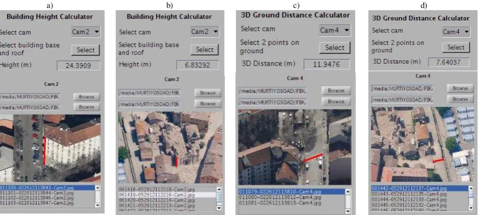
a) b) c) d)
Figure 4: Use of the monoplotting tool to derive building heights (a, b) and measure ground distances like street’s width (c, d) in urban and natural hazard scenarios.
4. EXAMPLES AND ANALYS ES
The primary function of the developed viewer application is to inspect the sides of a building from different oblique point s of view, once the building of interest is manually identified by the user in a nadir view (Fig.3). This is accomp lished by computing the object coordinates of the selected point and re-projecting them to the other available images using Eq. 1 and Eq. 2 as previously described.
Some examples of building height calculation and 3D ground distance measurment are shown in Fig. 4. An additional functionality, based on the measured building’s height, allows to derive the numbers of floors (Fig. 5).
As no ground truth data was available for these datasets, a comparison has been taken with the average height of buildings. According to the Council on Tall Buildings and Urban Habitat (www.ctbuh.org), a residential building with 6 stories should have an average height of 26.6 meters. The building height calculator gives a value of 24.4 meters for a residential building in the M ilan data set (Fig.4a).
Figure 5. Additional feature to automatically retrieve the number of floors once the building height is determined.
The monoplotting tool allows also façade digitization (Fig. 6) as well as the assignation of information related to damages (Fig. 7).
The user may digitize multiple images to get the coordinates of a building from various oblique points of view. The digitized 3D points can also be exported with attributes useful for further 3D modeling purposes (Fig. 8). However, the accuracy as well
as the precision of the 3D building blocks will be affected by the various assumptions of the monoplotting approach as well as by the quality of the available datasets.
Figure 6. Building’s façade digitization.
Figure 7. Digitization of building elements (wall, roof, window, etc.), assigning semantic information (and different colors) useful for damage
assessment.
5. CONCLUS IONS
The article reported the development of a monoplotting tool for extracting metric information from image datasets acquired with multi-camera systems. Several aspects will be improved and more capabilities will be added in the next developments. The tool will be soon available to the community for research purposes.
The precision of the digitization results is normally affected by the various assumptions of the monoplotting approach (e.g. vertical line or plane) as well as by the user expertise, resolution of the employed images and accuracy of the camera parameters.
assess damages after natural hazards. In particular, the digitization tool is very useful to quickly classify damages and provide information for the purposes of aid and relief planning. The tool is also a valuable solution for 3D reconstruction of man-made structures from historical images and could be used for multi-temporal (4D) analyses.
Figure 8. Examples of initial 3D building block reconstruction using the monoplotting tool. In case of damaged building, only the survived
structures are digitized and modeled.
ACKNOWLEDGEMENTS
The reported work was conducted during an internship of the first author on the research topic “Oblique Aerial Cameras” at the 3D Optical M etrology (3DOM ) research unit of the Bruno Kessler Foundation (FBK) in Trento, Italy. The authors wishes to acknowledge CGR Spa/Blom Italy for the provided data.
REFERENCES
Bozzini, C., Conedera, M . and Krebs, P., 2012. A new monoplotting tool to extract georeferenced vector data and orthorectified raster data from oblique non-metric photographs. International Journal of Heritage in the Digital Era, Vol. 1(3), pp.499-518.
Colomina, I., and M olina, P., 2014: Unmanned aerial systems for photogrammetry and remote sensing: A review. ISPRS Journal of Photogrammetry and Remote Sensing, Vol.92. 79-97
Fritsch, D., and Rothermel, M ., 2013. Oblique image data processing: potential, experiences and recommendations. Proc. 54th Photogrammetric Week, pp. 73-88
Gerke, M ., and Xiao, J., 2013. Supervised and unsupervised M RF based 3D scene classification in multiple view airborne oblique views. ISPRS Annals of Photogrammetry, Remote Sensing and Spatial Information Sciences, Vol. II-3/W3, pp. 25-30.
Gerke, M ., Slagboom, Y. and Vosselman, G., 2014. Oblique airborne photogrammetry. GIM International, Vol. 28(1), pp.18-21.
Gerke, M ., and Remondino, F., 2014. EuroSDR Survey - Oblique airborne photogrammetry: users’ and vendor’s view. GIM International, in press.
Jacobsen, K., 2008. Geometry of vertical and oblique image combinations. Proc. EARSeL Symposium, Istanbul, Turkey .
Höhle, J., 2008. Photogrammetric measurements in oblique aerial images. Photogrammetrie, Fernerkundung, Geoinformation, (1), pp.7-14.
Kraus, K., 2007. Photogrammetry: Geometry from Images and Laser Scans, Vol. 1, W. de Gruyter, 459 pages.
Nex F., and Remondino, F., 2013: UAV for 3D mapping applications: a review. Applied Geomatics, Vol. 6(1), pp. 1-15
Nex, F., Rupnik, E., and Remondino, F., 2013. Building footprint extraction from oblique images. ISPRS Annals of Photogrammetry, Remote Sensing and Spatial Information Sciences, Vol. II-3/W3, pp.61-66.
Nyaruhuma, J., Gerke, M ., and Vosselman, G., 2012. Verification of 3D building models using mutual information in airborne oblique images. ISPRS Annals of Photogrammetry, Remote Sensing and Spatial Information Sciences, Vol. I–3.
Rupnik, E., Nex, F. and Remondino, F., 2014. Oblique multi-camera systems: orientation and dense matching issues. International Archives of the Photogrammetry, Remote Sensing and Spatial Information Sciences, Vol. XL-3/W1, pp.107-114.