DESIGN OF MWIR CONTINUOUS ZOOM WITH LIGHT WEIGHT
J. J. Ge,Y. Qin, D.B.Deng c
Beijing Institute of Space Mechanics & Electricity, China, 100076
KEY WORDS: Infrared Lens, Zoom lens, MWIR, Lens Design, Aspheric surface
ABSTRACT:
A thermal imaging continuous zoom system is developed with light weight for airborne optoelectronic detection and tracking apparatus. The continuous zoom system provides 4X zoom range from the focal of 37.5 mm to150 mm. Based on the cool 640×512 detector with staring focal plane array (FPA), an optical system of middle infrared continuous zoom system is designed for airborne optoelectronic detection and tracking apparatus. The system is composed of a zoom system, a secondary imaging system and two reflectors. In order to improving the system performance, the whole system is adding four aspheric surfaces. The design results prove that the system worked at 3.7-4.8 µm has achieved the zoom of 37.5-150 mm, large zoom ratio of 4×and F number of 4, which can obtain the cold shield efficiency of 100% and the MTF more than 0.4 at the spatial frequency of 32 lp/mm closing to the diffraction limit. The overall lens length is 280mm and the weight is 197g. The optical system has the advantages of small volume, high image quality and simple structure.
1. INTRODUCTION
Infrared imaging technology is widely used in surveillance, reconnaissance, ground air defence, guidance and other fields. As infrared imaging system has good environment adaptability, good concealment, strong anti-jamming ability, the small volume, light weight and low power consumption of the system has pay attention by many researchers.
In this paper, a continuous zoom system with light weight for airborne photoelectric reconnaissance system is designed. In order to decrease the optical length and the glass diameter, the compensated zoom lens is chosen one lens with a negative compensator to shorten the focus length. The whole system is no longer than 280mm.
2. OPTICAL TRANMISSION
Based on the cool 640×512 detector with staring focal plane array (FPA), the cold stop of the detector needs to be as the aperture stop of the optical system. The continuous zoom system presented is based on the specification presented in table 1.
Tab.1 Characteristics of the optical design
Characteristics Typical Value
Waveband/µm 3.7~4.8
Pixel size/µm2 15×15
Image Plane Diagonal /mm 12.294 Focal Length Range/mm 37.5~150
F number 2
The structure of the continuous zoom system is shown in Figure 1. There are two stage optical parts in the system, which has an
intermediate image. One is the objective system and the other is the relay lens.
Fig.1 The structure of the zoom optical system
3. DESIGN PRINCIPLE
According to the requirement of design parameters in this system, the negative group compensation structure form is chosen as an initial structure calculation. Because the negative structure lens has shorter length than the positive structure lens in light weight [1]. At the same time, the lens system which constraints the aberration balance need to shorten the focus of the zoom group and the compensating group properly [2].
There are two main processes for the IR zoom system design. One stage is the Gauss solution and the other is the balance the aberration to the better performance [3]. The main task of the Gauss solution process is based on the focal length, relative aperture, image size and movable range in the system design. The main task of the aberrational design process is the optimization of the system to eliminate aberration which cause from the Gauss solution including the focal position and the lens curvature radius. To improve the system image quality, we use the aberration balance by the optical design software and choose the reasonable infrared optical materials. At the same time, we consider the difficulty of the preparation of infrared materials including the large size, high quality. The most International Archives of the Photogrammetry, Remote Sensing and Spatial Information Sciences, Volume XL-1/W2, 2013
UAV-g2013, 4 – 6 September 2013, Rostock, Germany
commonly infrared material which has good stability and sophisticated processing technology is selection, such as silicon (Si) and germanium (Germanium). Meanwhile, in order to ensuring the fixing error and the structure accuracy of the system, the diffraction surface is not adopted in the design process [4].
4. RESULT
4.1 Zoom optical structure
The design results prove that the system worked at 3.7-4.8 µm has achieved the zoom of 37.5-150 mm, large zoom ratio of 4×and F number of 2, which can obtain the cold shield efficiency of 100% and the MTF more than 0.4 at the spatial frequency of 32 lp/mm closing to the diffraction limit. The overall lens length is 280mm and the weight is 197g.
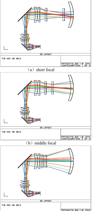
In order to performing a high quality, four aspheric surfaces are involved in the system. Figure 2 depicts the configuration of zoom optical system throughout the range, and the a、b、c are three typical focal short focal 、middle focal and the long focal system, separately.
a short focal
b middle focal
c long focal
Fig.2 Configuration of zoom optical system throughout the range
4.2 Zoom paths
According to the continuous zoom optical system, relative position between the zoom group and the compensating group and fixation group, fitting trajectory curve zoom group and the compensating group, as shown in Figure 3, where the abscissa represents variable distance fixed times group and the compensating group distance, longitudinal coordinate generation system focal length. It can be seen from Figure 3, in the entire zoom group curvature and the compensating group curvature are moving smoothly, which is beneficial for the manufacture.
Figure 3 depicts zoom paths of the system, the black line represent the zoom group motion and the red line represent the compensate group motion.
Fig.3 The zoom paths of the system
4.3 MTF
Modulation transfer function (MTF) is one of the main evaluation methods of optical system. Figure 4 depicts the MTF of the optical system for short focal、middle focal and the long focal. It can be seen from the figures MTF values in each field are greater than 0.4 at spatial frequency 32 lp/mm closing to the diffraction limit.
a short focal
International Archives of the Photogrammetry, Remote Sensing and Spatial Information Sciences, Volume XL-1/W2, 2013 UAV-g2013, 4 – 6 September 2013, Rostock, Germany
b middle focal
c long focal Fig.4 MTF curves of the system 4.4 Other evaluation
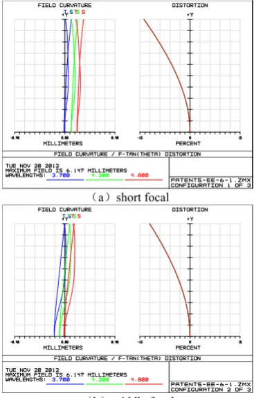
Figure 5 gives the system the field curvature in various focal case and distortion curve. It can be seen from the graph, the continuous zoom system distortion is less than 15%, the maximum value appears in the case of short focal, curvature of field are located between the -0.15mm - +0.15mm.
a short focal
b middle focal
c long focal
Fig.5 The field curvature & distortion
a short focal
b middle focal
c long focal
Fig.6 Diffraction in through focus MTF
Figure 6 shows the diffraction in through focus MTF at cut-off frequency.
5. CONCLUSION
A continuous zoom system with light weight is designed for airborne optoelectronic detection and tracking apparatus. The system worked at 3.7-4.8 µm has achieved the zoom range of International Archives of the Photogrammetry, Remote Sensing and Spatial Information Sciences, Volume XL-1/W2, 2013
UAV-g2013, 4 – 6 September 2013, Rostock, Germany
37.5-150 mm, large zoom ratio of 4×and F number of 2, which can obtain the cold shield efficiency of 100% and the MTF more than 0.4 at the spatial frequency of 32 lp/mm closing to the diffraction limit. The overall lens length is 280mm and the weight is 197g. The optical system has the advantages of small volume, high image quality and simple structure.
6. REFRENCES
[1] TAO cun-kan. Optical design of zoom system [M]. Beijing :National Defence Industry Press, 1988:78-81.
[2] Topaz a novel design of a high-magnification athermalized 1:30 zoom in the MWIR [C]. Proceedings of SPIE, Infrared Technology and Applications, 2004, 5406:97-106.
[3] Lin Da-jian.Engineering optical system design[M].Beijing: China Machine Press, 1987:387-388.
[4] WANG Zhi-jiang, GU Pei-sen. Handbook of applied optical technology[M]. Beijing: China Machine Press, 2006:380-381.
International Archives of the Photogrammetry, Remote Sensing and Spatial Information Sciences, Volume XL-1/W2, 2013 UAV-g2013, 4 – 6 September 2013, Rostock, Germany