DIRECT GEOREFERENCING OF UAVS
M. Bláha*, H. Eisenbeiss, D. Grimm, P. Limpach
Institute of Geodesy and Photogrammetry, ETH Zurich, 8093 Zurich, Switzerland - (henri.eisenbeiss, david.grimm, philippe.limpach)@geod.baug.ethz.ch and [email protected]
Commission VI, WG VI/4
KEY WORDS: UAV, Falcon 8, direct georeferencing, GPS, flight trajectory
ABSTRACT:
UAV systems have become an attractive data acquisition platform in emerging applications. As measuring instrument they extend the lineup of possible surveying methods in the field of geomatics. However, most of UAVs are equipped with low-cost navigation sensors such as GPS or INS, allowing a positioning accuracy of 3 to 5 m. As a result the acquired position- and orientation data fea-tures a low accuracy which implicates that it cannot be used in applications that require high precision data on cm-level (e.g. direct georeferencing). In this paper we will analyze the potential of differential post-processing of GPS data from UAV in order to im-prove the positioning accuracy for applications basing on direct georeferencing. Subsequently, the obtained results are compared and verified with a track of the octocopter carried out with a total station simultaneously to the GPS data acquisition. The results show that the differential post-processing essentially improved the accuracy of the Falcon position data. Thereby the average offset be-tween the data sets (GPS data, track) and the corresponding standard deviation is 0.82 m and 0.45 m, respectively. However, under ideal conditions it is even possible to improve this positioning accuracy to the cm-range. Furthermore, there are still several sources of error such as the offset between the GPS antenna of the Falcon 8 and the prism which is used for the track. Considering this fact there is further room for improvement regarding the here discussed positioning method.
* Corresponding author.
1. INTRODUCTION
1.1 Motivation
Nowadays Unmanned Aerial Vehicles (UAVs) are frequently used as measuring instrument in various applications. These systems enable a new kind of data acquisition in the field of geomatics. Since the equipment of UAVs mostly consists of cost-efficient sensors (e.g. GPS, INS, etc.), the accuracy of the captured position and orientation data is limited. According to that they can only conduce to approximate values in the photogrammetric data processing and in the generation of geo data. Though, by the method of differential post-processing of the GPS data, it is possible to improve the positioning accuracy. If accuracy on cm-level can be achieved in the process, the data can be utilized for the purpose of direct georeferencing. This referencing method has already been extensively researched in the classical airborne photogrammetry (e.g. Škaloud, 1999 or Cramer, 2001) and in the airborne laser scanning domain (e.g. Favey, 2001 or Limpach, 2010) using high-end and low-cost GNSS/INS systems. However, for UAVs only few studies focused on the direct georeferencing using low cost sensors (e.g. Eugster, 2007 and Eugster and Nebiker, 2009). For this reason, further improvements considering the direct georeferencing of UAVs can be expected in the future.
Preliminary works with respect to UAV tracking were conducted in Eisenbeiss et al. and Eisenbeiss (2009). In these studies first investigations related to UAV tracking and the analysis of the UAV trajectory (model helicopter copter 1B) were investigated. The work presented in this paper occurred based on several projects, which were accomplished with the UAV system Falcon 8 at the IGP (Institute of Geodesy and
Photogrammetry) at ETH Zurich. However, the position data of the Falcon 8 system was not analyzed in further detail so far. Therefore, the key aspect of this project is set on the investigation of the Falcon 8 position data.
1.2 Objectives
The goal of this paper is to analyze the potential of the positioning accuracy of the UAV system Falcon 8. Thereby the parameters of the orientation, which are also codetermined in the process of direct georeferencing, are not considered here. The focus is exclusively set on the differential post-processing of the acquired GPS data. In this process it is aimed at the evaluation of different GPS software packages and at the comparison of the obtained results. A further goal is to verify the post-processed GPS measurements with adequate reference data, which consists of a track of the octocopter with a total station.
1.3 Paper structure
After the introduction the octocopter Falcon 8 and some corresponding projects are introduced in chapter 2. Subsequently, chapter 3 describes the field works which were carried out in spring 2011. The acquired GPS and tracking data built the basis for the following data processing, which is the topic of chapter 4. In this part, a distinction is made between the evaluation of the GPS and tracking data. Finally, chapter 5 summarizes the most important conclusions of the data processing and gives an outlook on potential future work.
2. THE UAV SYSTEM FALCON 8
The UAV system Falcon 8 is an octocopter manufactured by the company Ascending Technologies GmbH (Figure 1). It was purchased at the IGP for teaching and research purposes in 2009. Since then, the Falcon 8 was part of several projects and student theses. A general evaluation of the system was accomplished in spring 2010 in a student thesis (Friedli, 2010). Furthermore, the 3D trajectory of the octocopter was analyzed in a lab course in fall 2010. The results featured an accuracy of 3 to 5 m, which corresponds to the specifications of the manufacturer company.
Figure 1. UAV system Falcon 8 during data acquisition.
The main components of the Falcon are a remote control, the flight control software and the octocopter itself. Equipped with eight rotors, the UAV system possesses a maximum payload of 500 g. Since the camera mounting system already weights 200 g, there are only 300 g for supplemental sensors remaining. Further important elements of the Falcon are three magnetometers, a barometric altimeter, an INS and a GPS. The last mentioned is a LEA 5T receiver by µ-blox, which is a single frequency GPS receiver. This means GPS data is only captured on the first carrier frequency (L1). The data is saved on a log-file on the SD card of the Falcon 8, from where it can be used for further processing procedures (Friedli, 2010).
3. DATA ACQUISITION
The results of this paper are based on data acquisitions accomplished in spring 2011 on the Campus Science City of ETH Zurich. The results of preliminary field works showed that the GPS measurements of the octocopter feature an inconstant sampling interval. This fact interferes with the differential post-processing of the data, and therefore also with the verification with the tracking data (chapter 4). In order to solve this problem a new firmware was installed on the Falcon.
3.1 Preparatory work
GPS reference station setup
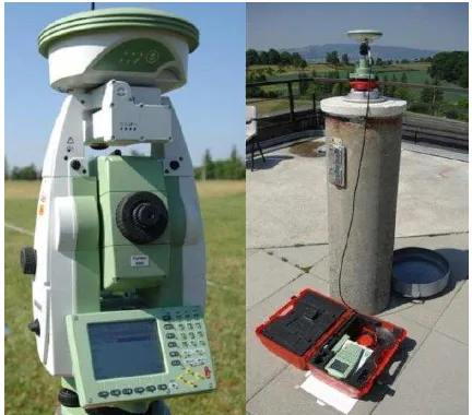
With respect to the differential processing of the GPS raw data of the Falcon it was necessary to set up a reference station during data acquisition. Since the coordinates of the pillars on the roof of the HIL building (Campus Science City) are already known, they emerged as ideal positions for this purpose. The instrument used was the Leica GPS1200 (Figure 2). In preparation of the data capture it was important to conduct correct settings on the reference station. In this context, the sampling frequency needed to be intermateable with the one of the GPS receiver of the UAV.
Figure 2. GPS reference station with Leica GPS1200 (right) and Leica SmartStation (left) during data acquisition.
Setting up of the total station
The Falcon was additionally tracked with a total station. Thereby a Leica SmartStation (Leica TPS1201 in combination with the corresponding Leica SmartAntenna) was applied as measuring instrument (Figure 2). Since the tracking data of the Leica TPS1201 features a high accuracy it is suited as reference data of the differentially processed GPS data (see Table 1). The hayfield in front of the HIL building emerged as appropriate location for the SmartStation.
Table 1. Measuring accuracy of the Leica TPS1201. Standard deviation
Angle measurement 0.3 mgon
Distance measurement on a prism (tracking)
5 mm + 2 ppm
In order to target the Falcon with the SmartStation, it was necessary to fix a reflector on the mounting system of the octocopter (Figure 3). In this project the Leica 360° mini prism was used. To maintain the maximum payload of 0.5 kg of the Falcon, the camera was removed for these data acquisitions.
Figure 3. Leica 360° mini prism mounted on the Falcon in order to accomplish the track with the total station.
Installation of the new Falcon 8 firmware
A new firmware - provided by Ascending Technologies GmbH - was installed on the Falcon 8. The analysis of the GPS data of
logged to the SD card at an inconsistent interval by the Falcon firmware. This circumstance influences the differential post-processing, and, therefore, also interferes with the tracking data verification, negatively. The origin of this problem was the former firmware of the Falcon 8. While the LEA 5T receiver is configured to provide four packages of GPS raw data per second (4 Hz), the former firmware stored only each fourth package in order to obtain a sampling frequency of 1 Hz. The µ-blox processor can sometimes get overloaded which leads to a missing 4 Hz data package, and hence to a shift of 0.25 s in the logged 1 Hz data at each missing package. The new Falcon firmware records all packages of raw GPS data. In this way, there are still several data gaps of 0.25 s, but the remaining measurements feature a consistent sampling frequency of 4 Hz.
3.2 Accomplishment of the data acquisition
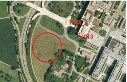
The field works were carried out on the hayfield next to the HIL building of the Campus Science City. As already mentioned above, the GPS reference station was positioned on the pillar 1013 and 1014 (preliminary field work) on the roof of the HIL building (see Figure 4).
Figure 4. Overview of the data acquisition area. The red circle signalizes the aviation area while the red dots point on the
positions of the reference station.
In good weather and with a wind speed of 1 to 4 m/s all field works were accomplished without unforeseen occurrences. The flight time amounted to approximately 5 minutes.
The GPS receiver of the Falcon was operated on the ground before and after the flight, allowing a more reliable analysis of the Falcon position data. The flight time of the octocopter is limited to roughly 10 minutes by the battery capacity. Consequently, it is not possible to capture long airborne data sets. However, on the ground most of the sensors can be shut down so that the whole system uses less energy. This approach enabled the acquisition of GPS records of approximately one hour.
For the direct comparison of the GPS and tracking data, it was necessary to synchronize the two measurement systems. This was achieved by a GPS measurement with the SmartStation. The tracking frequency itself was set to 10 Hz. However, based on the data analysis it was seen that the actual sampling frequency of the Leica TPS1201 varies between 4 and 6 Hz. With regard to the georeferencing of the track, four additional measurements to surrounding points with known coordinates were realized with the SmartStation. The coordinate accuracy is about 2 cm.
4. DATA PROCESSING
4.1 Processing of the GPS data
The GPS raw data are provided in the binary format of µ-blox (Falcon 8) and Leica (reference station). With regard to the differential post-processing in two different software packages, the data was converted into the RINEX (Receiver Independent Exchange) format. This step was realized using TEQC and Leica Geo Office (LGO) for the Falcon and Leica data, respectively. Subsequently, the differential post-processing of the GPS data was carried out with the software packages LGO and GrafNav. The results are presented in chapter 4.3 Evaluation of the results.
Concerning the verification with the track it was further necessary to adjust the frequencies of both data sets. In this paper only the 1 Hz frequency for the comparison is discussed.
4.2 Processing of the track
The binary raw data of the SmartStation was converted in LGO into an ascii file. Subsequently, a coordinate transformation (local coordinate system of the SmartStation LV95/LHN95) linear interpolation was accomplished in order to obtain a 1 Hz sampling frequency.
4.3 Evaluation of the results
Accuracy of the solutions in GrafNav and LGO
In a first step, the results of the differential processing in LGO and GrafNav were compared. The standard deviations in GrafNav were found to be significantly lower than those in LGO (Table 2). However, those values merely represent the software intern accuracy of the coordinates.
Table 2. Standard deviations σ of the coordinate solutions achieved in LGO and GrafNav.
Verification of the GPS results with the tracking data
For the comparison of the GPS and tracking data only the sampled data sets with a frequency of 1 Hz were used. The LGO results mostly feature a bigger shift to the track than the GrafNav data (Figure 5 and Figure 6). This fact supports the less accurate standard deviations mentioned above.
Figure 5. Footprints of the Falcon trajectories from LGO GPS post-processing, GrafNav GPS post-processing and tracking
data (total station).
Figure 6. Height profiles of the trajectories corresponding to Figure 5.
3D Euclidean distances between the GPS solutions (LGO and GrafNav) and the track were computed. Furthermore, the mean value and the corresponding standard deviation were determined for each data set. The same calculations were also carried out for the northing and easting component as well as for the height (Table 3). As typical for GPS measurements, the height features a lower accuracy than the horizontal coordinates. In addition, the values in Table 3 affirm the conclusions of the graphical analysis (see Figure 5 and 6). Both, the 3D distance as well as the standard deviation of the GrafNav results, related to the track, is smaller than in the LGO case. In a next step the spatial differences between the GPS results and the reference data were illustrated (Figure 7).
Table 3. Differences between the GPS results from differential post-processing and the tracking data.
LGO GrafNav 3D distance – mean value [m] 1.75 0.82 3D distance – standard deviation [m] 0.85 0.45
Easting dist. - mean value [m] 0.76 0.45 Easting dist. - standard deviation [m] 0.54 0.35 Northing dist. - mean value [m] 0.45 0.34 Northing dist. - standard deviation [m] 0.34 0.28 Height (orth.) Dist. - mean value [m] 1.33 0.45 Height (orth.) Dist. - standard
deviation [m]
0.91 0.38
Figure 7. 3D differences between the results of the differential GPS processing and the reference data (tracking data).
Finally, it has to be mentioned that both software packages were not able to solve the ambiguities of GPS phase measurements. While the LGO results correspond to a differential code solution, the GrafNav outcomes are mostly a differential phase solution with floating-point ambiguities. In the second half of the acquisition time the ambiguity status in GrafNav was fractionally even on fixed integer, whereby this part corresponds to the data which was captured after the flight on the ground. This data was further assayed in the following.
Advanced analysis of the GrafNav results
The focus of this paragraph is set on the ambiguity resolution of the GPS processing in GrafNav. A cluster of cycle slips appears during the flight of the octocopter (Figure 8). This leads to the presumption that the electronic equipment (e.g. antennas for the data transfer, electric motors of the rotors, etc.) of the Falcon influences the measurements of the GPS receiver during flight time negatively.
Figure 8. Cycle slips which were registered during data acquisition. The red points signalize the individual cycle slips.
The red circle points on the cluster of cycle slips during the flight of the octocopter. The flight corresponds to the time
interval from 34630 to 34850 s.
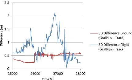
To analyze this fact, the GPS data acquired after the flight on the ground (chapter 3), was separately processed in GrafNav. Figure 9 shows the 3D differences between the GPS results and the reference position (tracking via SmartStation). The resulting mean value amounts to 0.45 m with a standard deviation of 0.25 m. Furthermore, the 3D differences between the GPS airborne data and the corresponding reference data were also plotted into the same figure. Compared to these values, a clear improvement was achieved through this approach, which supports the assumption that the electronic equipment of the
Figure 9. 3D differences between the GPS ground data and the reference position (tracking via SmartStation) compared to the
3D differences between the GPS airborne data and the corresponding reference data (Figure 7). The time scale of the
second mentioned data set was adjusted in order to enable a direct comparison of these two approaches. In addition, a
blunder in the GPS data acquired from the ground was eliminated, which corresponds possibly to a loss of signal lock
in the GPS phase measurements.
5. CONCLUSIONS
The outcomes of the field works showed that the new firmware conducted to a better position accuracy of the differential processed GPS data of the Falcon 8. Furthermore, the software package GrafNav turned out to be more appropriate than LGO in order to process this kind of GPS data (kinematic data of a single frequency GPS receiver). Thereby, it is to mention that the tracking of a UAV system during a real flight operation such as Falcon 8, the differential post-processing of its GPS data and the 3D analysis of the results have been done for the first time.
The verification of the post-processed GPS data was realized by a comparison with the track of the SmartStation. The resulting mean value between the data sets amounts to 0.82 m, with a dispersion (standard deviation) of 0.45 m. In contrast, the navigated positioning accuracy is 3 to 5 m. Accordingly, the position data obtained with the here presented method exhibits a clearly higher accuracy. However, under ideal conditions it is even possible to achieve a positioning accuracy on cm-level.
In spite of the above mentioned improvements, the results still
The data of the total station can also be optimized. The variable sampling frequency of the total station causes problems in the verification process of the GPS data. Thereby the presented method of linear interpolation is just an approximation of the reality. A further error source is assumed in steep sightings of the Leica TPS1201. This pretension is based on Figure 6, where the difference between the height profiles increases when the accuracy of a UAV trajectory based on low-cost GPS data was improved essentially. This was achieved by the method of differential post-processing of the GPS data and can be considered as one step towards direct georeferencing of cost-efficient UAV systems. But, the improvement of the orientation of such systems is still not solved yet and it is a possible research focus in future applications.
REFERENCES
Blaha, M., 2011. Direkte Georeferenzierung von UAVs. Masterprojektarbeit, ETH Zürich.
Cramer, M., 2001. Genauigkeitsuntersuchungen zur GPS/INS-Integration in der Aerophotogrammetrie. PhD thesis, Universität Stuttgart.
Eisenbeiss, H., 2009. UAV photogrammetry. DISS. ETH NO. 18515, doi:10.3929/ethz-a-005939264.
Eisenbeiss, H., Stempfhuber, W., Kolb, M., 2009. Genauigkeitsanalyse der 3D-Trajektorie von Mini-UAVs. In: Zukunft mit Tradition "29. Wissenschaftlich-Technische Jahrestagung der DGPF", Ed.: Seyfert, E., Publikationen der Deutschen Gesellschaft für Photogrammetrie, Fernerkundung und Geoinformation (DGPF) e.V., Potsdam, 407-417.
Eugster, H., 2007. Georegistrierung mittels Minidrohnen erfass-ter Videosequenzen – Ansätze und Genauigkeitsanalyse, in DGPF Tagungsband, SGPBF, DGPF und OVG Dreiländerta-gung 2007, 637-648.
Eugster, H., Nebiker, S., 2009. Real-time Georegistration of Video Streams from Mini or Micro UAS using Digital 3d City Models, 6th International Symposium on Mobile Mapping Technology, Presidente Prudente, Sao Paulo, Brazil, 22-24 July 2009.
Favey E., 2001. Investigation and Improvement of Airborne Laser Scanning Technique for Monitoring Surface Elevation Changes of Glaciers. PhD thesis No. 14045, ETH Zurich.
Friedli, E., 2010. Evaluation des Oktokopters Falcon 8. Bachelorarbeit, ETH Zürich.
Limpach P., 2010. Sea Surface Topography and Marine Geoid by Airborne Laser Altimetry and Shipborne Ultrasound Altimetry. Geodätisch-geophysikalische Arbeiten in der Schweiz. Volume 80. Schweizerische Geodätische Kommission. ISBN 978-3-908440-24-6.
Škaloud, J., 1999. Optimizing Georeferencing of Airborne Survey Systems by INS/DGPS. PhD thesis, University of Calgary.
ACKNOWLEDGEMENTS
The authors thank Jules Fenner (IGP) for providing the surveying equipment and Daniel Gurdan (Ascending Technologies GmbH) for technical support during this project. Furthermore, the authors thank Daniel Bäni, Michèle Brügger, Gabriel Flury, Wilfried Hartmann, Amanda Zwicky and the staff of the IGP who were involved in the field works of the project.