PRECISION ANALYSIS OF VISUAL ODOMETRY BASED ON DISPARITY CHANGING
C. Y. Fu a, J. R. Tsay a
a Dept. of Geomatics, National Cheng Kung University, Tainan, Taiwan - (P66044099, tsayjr)@ncku.edu.tw
Commission VI, WG VI/4
KEY WORDS: Visual Odometry, Disparity Changing, Mobile Mapping System, Six Degrees Of Freedom, Pose Estimation
ABSTRACT:
This thesis aims to analyze the precision of Position and orientation of cameras on Mobile Mapping System (MMS) determined by disparity based VO (DBVO). Dual forwards taken cameras on MMS are applied to obtain a sequence of stereo pairs. The Interior Orientation Parameters (IOPs) and Relative Orientation Parameters (ROPs) are derived in advance. The pose estimation is achieved by DBVO without additional control data. The procedure of DBVO consists of four steps. First up, keypoint detection and matching is conducted to obtain tie points in consecutive images. Then, image rectification is implemented to transform tie points into epipolar image space. Next, parallax equation is applied to estimate the 3D coordinates of interest points in epipolar image 3D space. Since their image points have different disparity in neighboring stereo pairs, the 3D coordinates of interest points in neighboring pairs are different as well. Finally, 3D conformal transformation is employed to derive the transformation parameters between neighboring pairs according to changing of coordinates of interest points. The posteriori STDs are adopted to assess the quality of transformation. Besides, check data of ground trajectory derived by photo triangulation are applied to evaluate the result. The relative errors of horizontal and vertical translations derived by DBVO are 2% and 3% in non-viewing direction. However, the translation in viewing direction and three rotation angles derived by DBVO have significant systematic errors about 1 m, 3°, 3° and 10° respectively. The influence of error propagation is not significant according to the chart of error distance ratio. In open area, the trajectory of INS/GPS is similar to ground truth, while the trajectory derived by DBVO has 44% relative error. In residential district, the trajectory derived by INS/GPS has drift error about 2 m, while the relative error of the trajectory derived by DBVO decreases to 38%. It is presumed that the systematic error results from 3D coordinates estimated by parallax equation because of poor intersection geometry. It will be proved by adding sideward photographing cameras in the future.
1. INTRODUCTION
1.1 Background
Mobile Mapping System (MMS) is a movable platform which integrates multiple sensors for spatial data acquisition. The selection of platform depends on the application. Aircrafts and Unmanned Aerial Vehicles (UAVs) are selected as platforms for wide area applications, such as urban planning, disaster prevention and generation of Digital Terrain Model (DTM). Land based vehicles (e.g., cars and bikes) are able to collect spatial data at street-level, and ships are chosen for bathymetric surveying. In indoor environment, human and robots are ideal platforms for exploration, rescue, etc.
Mapping and pose estimation are two main purposes of sensors on MMS. Former one is to acquire spatial data around the environment, and latter one is to determine the motion of MMS, also known as ego-motion. The pose of MMS means its position and orientation (Lu and Milios, 1997). In 3D space, the pose includes three translations and three rotations, which are generally named six Degrees of Freedom (6-DOF) (Saez et al., 2005). Inertial Navigation System (INS) is a well-known pose estimation sensor, but the drift error enlarges as time increases when INS is applied for navigation solely (Howard, 2008). Although Global Navigation Satellite System (GNSS) is usually integrated with INS to improve the positioning, the signals of GNSS are easily blocked in complex environment, which makes GNSS positioning become poor or even fail. Odometer is another solution for ego-motion determination of land based vehicles because it provides how long the MMS has driven
according to the rotation of the wheel. However, the distance given by odometer is incorrect when MMS is driving on rough terrain (Howard, 2008). Since sensors mentioned above all have the limitation on positioning, it is necessary to integrate mapping sensors to assist in ego-motion determination. Simultaneous Localization And Mapping (SLAM) is a concept to map the environment and to locate the platform at the same time.
1.2 Related Works
Visual Odometry (VO), which is to estimate 6-DOF ego-motion of cameras from a sequence of images (Nistér et al., 2004). There are three methods to achieve VO by features. First one is to construct the relative orientation of consecutive images by corresponding image points, which is named Structure from Motion (SFM) in photogrammetric computer vision. SFM is applied for not only 3D reconstruction but also camera motion recovery (Koch et al., 1998; Seitz et al., 2006; Chiuso et al., 2002). Another method is to construct ego-motion by tracking the features through sequential images (Howard, 2008; Geiger et al., 2011), which is called feature based VO. First up, features in previous stereo pair are transform to object space by space intersection. Then, image resection is conducted to derive the pose of current stereo pair. The ego-motion is constructed by minimizing the reprojection error in image resection. The other method is disparity based VO. Since the distance between camera and object static point is variant when camera is moving, the disparity of the static points is different in sequential images. Therefore, ego-motion is estimated according to the disparity changing. The disparity based VO is applied for indoor robot The International Archives of the Photogrammetry, Remote Sensing and Spatial Information Sciences, Volume XLII-2/W6, 2017
navigation by Hirschmüller et al. (2002). The approaches of VO mentioned above are all based on features. Engel et al. (2017) proposed direct sparse VO, which used intensity gradient of pixels instead of features to construct ego-motion.
1.3 Motivation
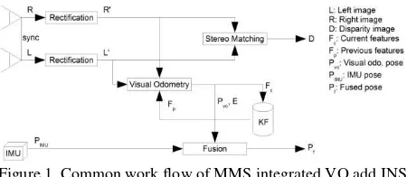
Since cameras are cheap and light-weight, VO is an ideal solution to assist in pose estimation (Hirschmüller et al., 2015). Figure 1 shows the common work flow of MMS integrated VO and INS. The basic equipment of MMS is Inertial Measurement Unit (IMU) and two forwards taken cameras. The Interior Orientation Parameters (IOPs) and Relative Orientation Parameters (ROPs) of cameras should be known in advance. Mapping and pose estimation are implemented individually in the work flow. First up, sequential stereo image pairs are derived and are rectified. Then, stereo matching is applied for dense image matching, and VO is integrated with IMU to construct ego-motion. Stereo matching is to calculate pixel-wise disparity in one image, and then to search the corresponding points in another one according to the disparity. Since the disparity is in pixel level or even sub-pixel level, the density of point cloud is usually high enough to store detailed spatial data around the environment.
Figure 1. Common work flow of MMS integrated VO add INS (Hirschmüller et al., 2015)
This paper intends to integrate disparity based VO and stereo matching to accomplish SLAM for land based vehicle. Though stereo matching calculates pixel-wise disparity for dense image matching, the quality of disparity is unstable, especially at matching and disparity based VO to accomplish SLAM for land based MMS. VO is seldom discussed in past studying. Only Hirschmüller et al. (2002) applied disparity based VO for indoor robot navigation, and there is no research in outdoor environment so far. Therefore, before developing the integration of disparity based VO and stereo matching, the performance of pose estimation by disparity based VO in outdoor environment should be discussed.
In this thesis. disparity based VO (DBVO) is performed to determine the pose of cameras on MMS. Since single camera cannot obtain disparity and multiple camera system is too complex, dual forwards taken cameras are selected in this research. Dual cameras should be calibrated to obtain their IOPs and ROPs in advance. The Exterior Orientation Parameters (EOPs) of cameras at first exposure station are known to transform the ego-motion derived by DBVO from local coordinates system to mapping frame. In the experiment, ego-motion construction is accomplished by DBVO only without integrating additional information, such as GNSS, INS and control points.
This research aims to analyze the precision of pose of dual forwards photographing cameras on MMS estimated by DBVO. The posteriori Standard Deviations (STDs) of 6-DOF obtained by DBVO are adopted to assess the process. Besides, Ground Truth (GT) trajectory derived by photo triangulation (PT) is applied to evaluate the precision of 6-DOF of cameras determined by DBVO. Furthermore, the baseline length of dual cameras on MMS is much shorter than the distance between object point and cameras, which results in poor intersection geometry. The relation between the intersection geometry and the pose estimation by DBVO is discussed.
2. DBVO
The concept of DBVO is to construct the ego-motion of camera according to the disparity changing. First up, keypoint detection and matching have to be conducted to obtain tie points which connect sequential images. Then, all points are transformed to epipolar image space after image rectification. In epipolar image space, parallax equation is applied to estimate the 3D coordinates of interest points located at left epipolar image space. Since their image points have different disparity in neighboring stereo pairs, the 3D coordinates of interest points in neighboring left epipolar image space are different as well. Therefore, 3D conformal transformation is implemented to derive the 6-DOF between neighboring pairs according to the conducted keypoint detection and matching entirely to obtain tie points connecting consecutive stereo pairs. Practically speaking, however, it is recommended that keypoint detection and matching should be implemented incrementally in the future. The lens distortion of image coordinates of tie points is removed by using additional parameters from priori IOPs.
2.2 Image Rectification
The purpose of this step is to transform the image coordinates of tie points from original image space to epipolar one. Homography based image rectification method proposed by Fusiello et al. (2000) is adopted, which is divided into 2 steps. One is to transform the stereo pair into coplanarity to become truly vertical pair. Another step is to rotate the image plane and image row direction to be parallel to the baseline. The former step of rotation can be achieved by rotation matrix R consists of ROPs or EOPs of original stereo pair. The latter step is to directly form the rotation matrix R by (1) to (4). After R is The International Archives of the Photogrammetry, Remote Sensing and Spatial Information Sciences, Volume XLII-2/W6, 2017
derived, the homography matrix H is obtained: H= RN RT. After image rectification, corresponding tie points, whose y parallax is more than 1 pixel, are regarded as outliers because the correct conjugate points should not have y parallax after image rectification (Wolf et al., 2014).
(1)
(2)
(3)
(4)
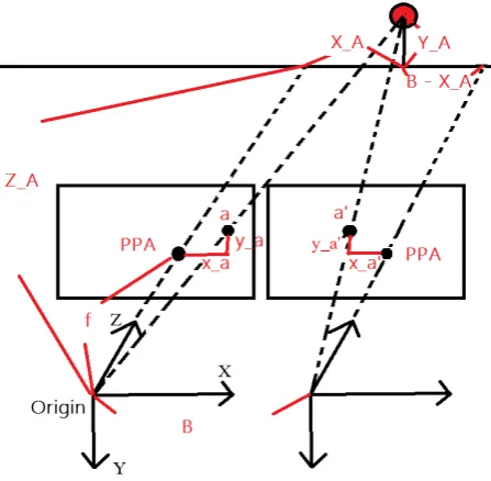
where = X-axis of epipolar image, which is parallel to baseline = the Y-axis of epipolar image, which is orthogonal to and . = an arbitrary unit vector to fix Y-axis position. Original Z-axis is selected as . = the Z-axis of epipolar image, which is orthogonal to and . 2.3 Parallax Equation for MMS Parallax equation is useful for aerial stereo pair to estimate 3D coordinates of object points by similar triangle in truly vertical situation (Wolf et al., 2014). However, the geometry of forward taken cameras on MMS is different from that of aerial stereo pair. The datum of parallax equation for aerial stereo pair is mapping frame, but the datum of parallax equation for MMS is left epipolar image space. In left epipolar image space, the origin is set at the projection center of left image. X-axis is along to image row direction, and Y-axis is along to image column direction. Z-axis is in the depth direction. Figure 2 illustrates the geometry of MMS, and the parallax equation for MMS is described by (5), (6) and (7). Figure 2. The geometry of MMS (5)
(6)
(7)
2.4 3D Conformal Transformation In this section, 3D conformal transformation with scale invariant is introduced. The unknown transformation parameters include 6-DOF (3 translations and 3 rotation angles), and the transformation is shown as (8). (8)
where
, , , = object coordinates of point A. , = left image coordinates of point A.
, = right image coordinates of point A. = disparity of point A.
, = baseline and flying height.
Since (8) is non-linear equation, Taylor series expansion is applied to linearize the equation by taking terms with 0 order and 1st order. The initial approximate values of unknowns are set as zero in this case. After that, a linearized observation equation system is constructed, and least squares adjustment is applied to obtain the most probable transformation parameters. Since the observation equation system is approximated by Taylor series expansion, the adjustment has to be conducted iteratively until the increments of unknowns are lower than the given threshold. Each point is assumed as equal weight, so the weight matrix is identity one.
3. EXPERIMENT & ANALYSIS
This paper aims to analyze the precision of pose of dual forwards taken cameras determined by DBVO. Section 3.1 represents the testing data and pre-processing step. Section 3.2 shows evaluation of ego-motion constructed by DBVO. Section 3.3 describes the relation between precision of pose estimated by DBVO and moving distance. Last but not least is that the relation between the intersection geometry and precision of pose estimated by DBVO are discussed in section 3.4.
3.1 Materials and Pre-processing
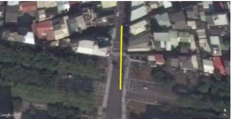
In this thesis, 22 stereo pairs (44 images totally) taken by dual forwards taken cameras on MMS are chosen as testing data. The cameras equipped on MMS is A102K industrial ones produced by Basler, and the lens is produced by Computar whose focal length is regarded as constant (Wu, 2009). The MMS drove along a straight street, and the moving direction is almost parallel to Y axis in mapping frame (Figure. 3). The distance of the path is about 50 m.
Figure 3. The trajectory of testing data (from Google Earth) Yellow line represents the trajectory of MMS.
In the pre-processing step, self-calibration bundle adjustment is implemented by software Pix4DMapper and Australis. After adjustment, the IOPs of cameras and ROPs of each stereo pair are derived as priori information displayed in Table 1.
Cam 1 Cam 2
Image size (pixel) 1392 * 1040 Pixel size (μm) 6.45 * 6.45
Focal length (mm) 8.259 ± 0.003 8.266 ± 0.002 Principal point (mm) (0.109 ± 0.007,
0.027 ± 0.007)
(0.016 ± 0.003, 0.058 ± 0.003) Baseline length (m) About 1.6
Table 1. Priori information of 2 forward cameras on MMS
3.2 Evaluation of Ego-motion Construction by DBVO
In this section, each ego-motion is constructed by two neighboring stereo pairs only. Therefore, every ego-motion is regarded as independent pattern to one another. First up, after 3D conformal transformation, the posteriori STDs of ego-motions are derived. Table 2 shows the RMS of posteriori STDs of ego-motion parameters. Theoretically speaking, the precision along depth direction should be worse than other directions because of intersection geometry. However, the posteriori STD in moving direction (Y-axis) is lower than other directions, and κ (heading angle) has the best precision of the three.
Translations Posteriori STD (cm)
Posteriori STD (degree)
Rotation angles
X 4.3 0.0325 Ω
Y 1.8 0.0220 Φ
Z 6.8 0.0191 Κ
Table 2. RMS of posteriori STDs of ego-motion
Then, each ego-motion is evaluated by ground truth trajectory, respectively. The ground truth data is calculated by photo triangulation. Figure 6 describes the difference between ego-motion by DBVO and ground truth in translations. The differences in X and Z seems random, but there is a significant negative bias in in Y-axis. Table 3 represents the statistic values of the differences in translations. The maximal absolute differences in X and Z are lower than 0.2 meter, and the mean errors are in centimeter level. The systematic bias in Y-axis is about -1 meter. The difference of rotation angles of ego-motion is in Figure 7, which shows that there are negative systematic biases in 3 rotation angles. In Table 4, the statistic values of the differences in rotations is listed, and κ (heading angle) has the biggest RMSD of the three.
The posteriori STDs are at centimeter level in the translations and about 0.01° in the rotations. Y-axis (viewing direction) and
κ (heading angle) has the lowest STD, respectively. However, the comparison with ground truth shows that the translation of ego-motion in viewing direction is actually shorter than real
trajectory for about 1 m, and difference of κ is about 10°, which
is the worst of the three rotation angles. To sum up, the posteriori STDs given by 3D conformal transformation are too optimistic. Moreover, they cannot detect significant mistakes of ego-motion.
Figure. 6 Difference of translations between ego-motion and ground truth
Min Max Mean RMSD
X (m) -0.133 0.103 -0.029 0.069
Y (m) -1.311 -0.810 -1.051 1.056
Z (m) 0.000 0.155 0.068 0.080
Table 3. The statistic values of difference of translations
Figure 7. Difference of rotations between ego-motion and ground truth
Min Max Mean RMSD
ω (degree) -4.8646 0.5263 -2.3327 2.6118 φ (degree) -5.0928 1.6174 -2.0323 2.6546 κ (degree) -11.7216 -8.1003 -9.7213 9.7954 Table 4. The statistic values of difference of rotation angles
3.3 Quality between DBVO and distance
In this section, every independent ego-motion derive by DBVO is combined together to generate a track, which represents the result of DBVO on navigation application. Trajectories of ground truth and INS/GPS are given for evaluation.
Figure 8 shows the cumulative translation differences between ego-motion by DBVO and ground truth trajectory. Error propagation is not significant in X-axis and is a little in Z-axis. However, the more distances, the higher accumulation of The International Archives of the Photogrammetry, Remote Sensing and Spatial Information Sciences, Volume XLII-2/W6, 2017
difference in moving direction (Y-axis). Figure 9 describes the ratio of difference and distance. The ratios in X, Y and Z direction are stable at 2%, -40% and -3%. The error distance ratio does not increase when distance becomes longer.
Figure 8. Cumulative errors of translations
Figure 9. Error distance ratio
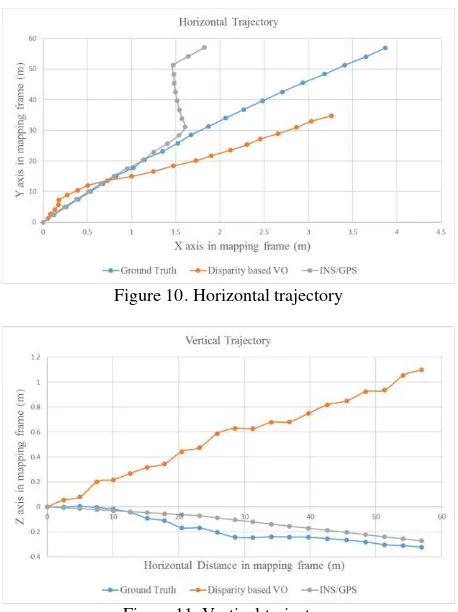
Figure 10 and Figure 11 illustrate the horizontal and vertical trajectories derive by DBVO, photo triangulation (ground truth) and INS/GPS. In the horizontal trajectory, the trajectory of INS/GPS is very similar to the ground truth at the beginning, but the trajectory of INS/GPS drifts away in the middle of the street. By contrast, the trajectory of DBVO is much shorter than ground truth at the beginning, and becomes more similar until MMS drove through the middle of the street. At the beginning of the street, the MMS was driving through the crossroad. Since there are few obstructions at the intersection, the result of INS/GPS is precise and stable. On the other hand, the intersection lacks textures, which are important for keypoint detection. Therefore, the trajectory of DBVO is worse and unstable. In the middle of the street, the MMS was surrounded by buildings. In this case, the signals of GPS are easily blocked, which is easily make the INS/GPS result drift. However, since the texture becomes abundant, the result of DBVO is improved. In the vertical trajectory, the performance of INS/GPS is similar to ground truth. Though the bias of DBVO enlarges as distance increases, it is admissible because the relative error is only 3%.
Figure 10. Horizontal trajectory
Figure 11. Vertical trajectory
3.4 The Influence of MMS Geometry
Above discussion represents that ego-motion constructed by DBVO has significant negative bias in viewing direction of translation and 3 rotation angles, but the performance of translations in non-viewing direction is fine (relative error is lower than 3%). Since ego-motion is constructed by difference of tie points coordinates determined by parallax equation, this section takes insight into the precision of parallax equation calculation.
In MMS geometry, the baseline length is much shorter than the distance between camera and object points. In the case of this testing data, the baseline length is about 1.6 meters and the average depth is around 40 meters. Therefore, the base-to-height ratio is only 0.04, which is much lower than 0.3 (the standard base-to-height ratio for national mapping by aerial photogrammetry in 1/1000 scale in Taiwan).
The most probable object coordinates of tie points given by ground truth are applied to evaluate the precision of parallax equation calculation. The ground truth coordinates are transformed from mapping frame to epipolar image 3D space, which is the same as parallax equation result. Table 5 describes the statistic values of difference between parallax equation and ground truth. The RMSD is 3 meters in baseline direction. In direction of image column, the RMSD is 7.2 meters because the maximal difference is about 28 meters, which is regarded as blunders. In depth direction, the minimal and maximal differences are negative, which represents the depths of tie points estimated by parallax equation are totally shorter, and the bias is about 8.4 meters.
Min (m) Max (m) Mean (m)
RMSD (m)
Row -8.667 1.105 -2.454 3.007
Column -4.798 27.957 4.421 7.203 Depth -30.031 -0.372 -6.816 8.365 Table 5. Difference between parallax equation and ground truth
Next, the influence by distribution and number of tie points is discussed. Image is divided into 13*10 sub-regions and the number of tie points in each sub-region is classified into 4 categories according to the quartile respectively in Figure 12. Category 1 is the sub-regions whose tie points are fewer than 12, which means that those sub-regions lack textures. By contrast, sub-regions in category 3 have abundant textures for keypoint matching because numbers of points in those regions are more than 59. Figure 13 represents the mean difference between parallax equation and ground truth in each category. There is a positive bias in column direction, and negative ones in other direction. Figure 14 describes the RMSD of parallax equation result. The mean differences and RMSDs in different categories are similar. To sum up, the calculation of parallax equation is independent to the textures and tie point distribution.
Figure 12. The distribution of tie points in image frame Gray means no tie point in sub-region. Blue means number of points in sub-region is between 1 and 12. Orange means number
of tie points in sub-region is between 13 and 58. Green means that number of tie points in sub-region is more than 59.
Figure 13. Mean difference in case of different number of tie points
Figure 14. RMSD in case of different number of tie points
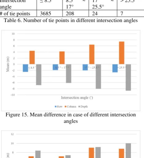
The standard base-to-height ratio for national mapping by aerial photogrammetry in 1/1000 scale in Taiwan is 0.3, and its intersection angle is about 17°. Therefore, the intersection angles of tie points are classified into 4 categories (≤ 8.5°, 8.5° ~ 17°, 17° ~ 25.5° and > 25.5°). Number of tie points in each category is in Table 6. The mean difference and RMSD of parallax equation result in each category are calculated respectively in Figure 15 and Figure 16. Theoretically speaking, as the intersection angle increases, the depth precision is improved but non-depth ones become worse. In the studying case, however, the intersection angle between 8.5° and 17° is better than other angles. Moreover, the difference becomes greater when intersection angle is larger than 17°. Although the intersection angles are at least 28°, their base-to-height ratios are merely 0.03 to 0.09. Therefore, the intersection angle is not suitable to evaluate the quality of geometry.
Intersection angle
≤ 8.5° 8.5° ~ 17°
17° ~ 25.5°
> 25.5°
# of tie points 3685 208 24 7
Table 6. Number of tie points in different intersection angles
Figure 15. Mean difference in case of different intersection angles
4. CONCLUSIONS
This paper aims to analyze the precision of pose of dual forwards taken cameras determined by DBVO. In this research, dual forwards taken cameras are applied to obtain a sequence of stereo pairs and DBVO is proposed for positioning and navigation without additional control data.
In conclusion, ego-motion constructed by DBVO has 2% and 3% of relative errors in horizontal no-viewing direction and vertical one, which is good enough for navigation application. The influence of error propagation is not significant. Besides, INS/GPS performs well in open area, while DBVO have good performance in complex environment. Therefore, it is recommended that INS should integrate both GPS and DBVO for localization. However, translation in viewing direction and rotation angles derived by DBVO remain significant systematic error about 1 m, 3°, 3° and 10° respectively. The reason is that the coordinates estimated by parallax equation is unstable because of poor intersection geometry. Therefore, it is suggested that side viewing cameras should be added to improve poor geometry of forward cameras on MMS.
REFERENCES
Agarwal, S., Furukawa, Y., Snavely, N., Simon, I., Curless, B., Seitz, S. M., and Szeliski, R. (2011). Building Rome in a Day. Communications of the ACM, vol. 54(10), pp. 105-112.
Chiuso, A., Favaro, P., Jin, H. and Soatto, S. (2002). Structure from Motion Causally Integrated Over Time,” PAMI, vol. 24 (4), pp. 523–535.
Engel, J., Koltun, V., and Cremers, D. (2017). Direct sparse odometry. IEEE Transactions on Pattern Analysis and Machine Intelligence.
Fusiello, A., Trucco, E., and Verri, A. (2000). A compact algorithm for rectification of stereo pairs. Machine Vision and Applications, vol. 12 (1), pp. 16-22.
Geiger, A., Ziegler, J., and Stiller, C. (2011). Stereoscan: Dense 3D Reconstruction in Real-time. Paper presented at the Intelligent Vehicles Symposium (IV), 2011 IEEE.
Hirschmüller, H., Innocent, P. R. and Garibaldi, J. M. (2002). Fast, Unconstrained Camera Motion Estimation from Stereo without Tracking and Robust Statistics. Paper presented at the Control, Automation, Robotics and Vision, 2002. ICARCV 2002. 7th International Conference on.
Hirschmüller, H., Schmid, K., Suppa, M. (2015). Computer Vision for Mobile Robot Navigation. Photogrammetric Week 2015, pp. 143-154.
Howard, A. (2008). Real-time Stereo Visual Odometry for Autonomous Ground Vehicles. Paper Presented at The 2008 IEEE/RSJ International Conference on Intelligent Robots and Systems.
Koch, R., Pollefeys, M. and Van Gool, L. (1998) Multi viewpoint stereo from uncalibrated video sequences. In ECCV, pp. 55–71.
Lu, F. and Milios, E. (1997). Robot Pose Estimation in Unknown Environments by Matching 2D Range Scans. Journal of Intelligent and Robotic systems, vol. 18(3), pp. 249-275.
Nistér, D., Naroditsky, O., and Bergen, J. (2004). Visual Odometry. Proceedings of the 2004 IEEE Computer Society Conference on, vol. 1, p. I.
Saez, J. M., Escolano, F., and Penalver, A. (2005). First Steps towards Stereo-based 6DOF SLAM for the Visually Impaired. In Computer Vision and Pattern Recognition (CVPR) Workshops, 2005. IEEE Computer Society Conference on. pp. 23-23.
Seitz, S. M., Curless, B., Diebel, J., Scharstein, D. and Szeliski, R. (2006). A Comparison and Evaluation of Multi-View Stereo Reconstruction Algorithms. In CVPR, pp. 519–528.
Wolf, P. R., Dewitt, B. A., Wilkinson, B. E. (2014). Elements of Photogrammetry with Applications in GIS, 4th edition. New York: McGraw-Hill Education.
Wu, K. Y. (2009). Utilization of Object Space Conditions for Camera Calibration of A Mobile Mapping System. M.S. thesis, National Cheng Kung University, Tainan, Taiwan.