ROAD NETWORK EXTRACTION FROM DSM BY MATHEMATICAL MORPHOLOGY
AND REASONING
Yan Lia, *, Jianliang Wua, Lin Zhub, Kikuo Tachibanab
a International Institute for Earth System Science, Nanjing University, China - [email protected], [email protected] b Research & Development HQ, PASCO Corporation, Japan, (luihnz7801, tachibana_kikuo)@pasco.co.jp
Commission II, /THS-17
KEY WORDS: Road extraction, Digital Surface Model, Morphology
ABSTRACT:
The objective of this research is the automatic extraction of the road network in a scene of the urban area from a high resolution digital surface model (DSM). Automatic road extraction and modeling from remote sensed data has been studied for more than one decade. The methods vary greatly due to the differences of data types, regions, resolutions et al. An advanced automatic road network extraction scheme is proposed to address the issues of tedium steps on segmentation, recognition and grouping. It is on the basis of a geometric road model which describes a multiple-level structure. The 0-dimension element is intersection. The 1-dimension elements are central line and side. The 2-1-dimension element is plane, which is generated from the 1-1-dimension elements. The key feature of the presented approach is the cross validation for the three road elements which goes through the entire procedure of their extraction. The advantage of our model and method is that linear elements of the road can be derived directly, without any complex, non-robust connection hypothesis. An example of Japanese scene is presented to display the procedure and the performance of the approach.
* Corresponding author
1. INTRODUCTION
Road extraction methods vary greatly due to the differences of data types, resolutions, urban or rural, et al. When resolutions lower than 10 meter, roads are characterized by lines. The extraction methods can be edge based line extraction and associated serious processing, such as SORM(Doucette, 2001; Doucette, 2004; Wiedemann, 2000), and the roads can be represented in 1D features. In high resolution imagery or DSM the roads are much wider and present not only lines in their sides, but also areas within the sides. It needs more complex model to explain the roads. Also it means that more complex method is required.
The other factor deciding the method is the data source. There are more advances using DSM to extract roads than using spectral imagery. For example, it is free from spectral effects caused by different materials, shadow or blocking by buildings, etc. DSM provides height data of each terrain cell which is useful for direct classification or segmentation of the off-terrain and the ground. The difficulty might be the determination of ground points belonging to the roads, because some open space connecting to the road have the same height with the road. All in all, the characteristics of line type of the roads can be applied for determination. DSM data is more and more available by both photogrammetry or LiDAR and more people use DSM to extract road networks (Hu, 2004; Jung 2006). Using DSM to generate road network is convenient and cost-efficient.
Most previous methods initialize the algorithms by pixel based or line based detection/classification/segmentation (Hinz 2003; Zhang 2007; Close, 2004). Segment primitives and connection hypothesis are needed for most pixel based or object based road
extraction. Taking Grote's work (Grote, 2012) as example, the road extraction starts with a segmentation using the normalised cuts algorithm, afterwards the segments are grouped. Road sections are extracted from the grouped segments. Road sections that are likely to belong to the same road are connected to sub-graphs in the next step. To eliminate false connections in the sub-graphs, context objects such as vehicles, buildings and trees are employed. The remaining road strings, represented by their centre lines, are connected to a road network. Similar methods can be found in other literatures (Baumgartner, 1997; Baumgartner, 1999; Lu, 2014). Zhao etc (2011) proposed a classification based method, where LIDAR data is used for rapid road network extraction. The main procedure includes three steps. 1) terrain separation from DSM and classification of ground features, 2) road central line extraction from generated road candidates images, and 3) completion and verification of complete road networks. From the mask-superimposed intensity image, road pixels are detected by supervised classified. On this image, some false negative pixels (pixels of other classes classified as roads) still exist while some true roads are misclassified. The extracted central line is not guaranteed continuous. As we can find, the biggest problem of this kind of methods is the complexity due to less of inner logic of some steps, for instance, edge point grouping or linking. There must be many errors remains and it is difficult to handle these errors because the algorithms take hardly advantage of topological relation. The errors in the first steps such as edge detection may propagate to the following steps and easily cause wrong road connections. These problems generally are faced by image based road extractions, and also by DSM based extractions.
Rajeswari (2011), they used level set method to search the road operations and cross validations. There are two main advantages of our model and method. The line feature of the road can be derived directly. The road central lines and road sides are continuous inherent from the beginning of the algorithm.
2. METHODS
2.1 Road Model and Technique Sketch
The road network extraction scheme is on the basis of all element road model. The road elements include central line, road side, intersection, and the interior planar. The road model is described by the hypotheses of the relationship of the elements. Their scale relationship determines the progressive extraction, and their spatial relevance supports the cross-validation. The intersection is point feature, the lower scale element of the road, while the road central line and side are line features, the higher scale elements. The interior plane is the area feature, higher than lines and sides, and will implicitly buildings and houses. We can extract the blocks and regularize the outline of them firstly. Then road sides and road central lines are generated according to their topological relationships to the blocks.
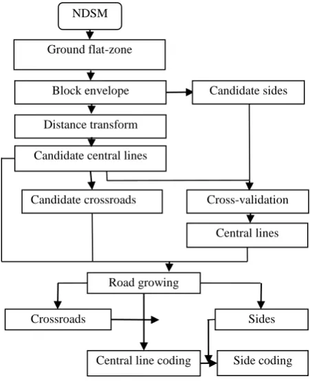
Figure 1 illustrates the proposed method by a flow chart. The procedure starts with flat zone labeling and height thresholding. The off terrain objects are extracted as the complementary sets accordingly. The blocks and their envelopes are generated respectively using Mathematical Morphology. The optional road central lines are derived by distance transform and watershed on the ground other than blocks. The intersections, road central lines and road sides are generated and cross-validated in the procedure.
Many research segment the ground by thresholding to the DSM (Stolpe, 2013; Herumurti, 2013). For complex urban planning it is easy to cause errors. Herein the ground area is extracted using morphological operations. Flat zones are firstly extracted as the ground's basis. It refers to a connected region of the DSM, in which all the pixels have the same gray-level (or height). Gray levelling and labelling are implemented to extract the flat zones. To avoid extracting rough objects, the approximate flat zone is introduced that use a parameter to filter the small area zones. Also a parameter is defined to permit the height difference within a zone. Ground is extracted by threhsolding the height of the flat zones using the average height of the DSM. Some operations such as hole filling is implemented to the result and the initial ground is generated.
Figure 1. Flow chart of the method
2.2 Block and Convex-Concave Hull
In the ground map, the extracted roads and open spaces are labelled as 1, while other pixels labelled as 0. Streets between the blocks are obvious and connective. But the contour of them is not as smooth and straight as enough, because the boundary complementary set of the regularized block hulls.
A block’s outline can be represented by an envelope radius of the circle. Thus we choose the convex hull to represent the outline. The convex hull is the maximal alpha shape. The advantage of convex hull are: it is unique and independent of any parameters because of the characteristics of delauney triangular; and the lines of the hull are straight which can be used to create straight central lines in the following stages.
However, some block is not a square or rectangular shape, even not a convex shape. Thus some convex hulls of neighboring blocks may be overlapped with each other. It must be processed to detect which one is actually concave and modify it to a concave hull. Considering the overlapped two convex hulls, if one of them has the are ratio of the corresponding block to the convex hull less than 0.5, the block is taken as concave and should be replaced by the smoothed shape in a larger parameter.
2.3 Extraction of Road Elements
2.3.1 Central Line: The road central line is generated by
distance transform. In a binary block hull image the inner hull pixel is labelled as 1 and background as 0. Taking the complementary set of the hull image, the road should be included in the sets of 1. For an object of 1, the distance of a inner pixel is defined as its minimal distance to the object boundaries. Thus the most inner pixel has the maximal distance comparing with its surroundings, while the edge pixels have the minimal distances. The road central line should be composed of such pixels that have the local maximal distances among the road object. To get the continuous line, we generate the road central line by the watershed segmentation to the distance map, where the blocks are the basins. The watershed is continuous and of single pixel width.
Figure 2 show the central line generation procedure of a testing DSM. Figure 2(a) presents part of the block hulls in gray, and (b) is the associated distance transform. The brightness corresponds to the distance. The ground with big area will has much greater distances comparing with the roads. Accordingly, they are much brighter than the general roads in the map. Figure 2 (c) shows generated possible (optional) central lines in black. The optional lines are also referred to as validated (TBV) road center LTBV{ }p , which is a set of points p.
(a) Blocks map
(b) Distance map
(c) Road central lines Figure 2 Central line generation
From Figure 2 (c) we can find that there are some false central lines detected in the big empty ground areas, because the watershed algorithm generate non broken lines. Something should be taken to detect and delete the false ones. This will be carried out in road growing.
2.3.2 Road Side: Noticing that the road sides are parts of
block hulls, we developed a cross validation method to detect the real central lines and the road sides in the meanwhile, which is called central line validation. We use the TBV lines LTBV to detect the road sides STBV from the block hulls, and then use the STBV to verify and extract the real central lines as validated central lines LVAL.
To do so, the TBV central lines are dilated to some extent with a structural element (SE) to make a pseudo road plane R(p), which should be beyond the real road width. It can be set according to the resolution of the data and the practical road width. The pixels in the hull boundaries intersected with the pseudo road plane are extracted as the road sides STBV. The road sides are line sections belonging to different block hulls, as shown as the light colour lines in Figure 3 for example. By doing this, there will be no road sides detected beside the false TBV central line, because no blocks are extracted at the big open spaces.
{ |
( );
}
TBV
S
q q
H
R p q
(1)
Then we can derive the real Lval. by dilating STBV to a road plane
width again and taking the intersections of the LTBV and the dilated sides. They are line sections broken at the crossroads like the road sides, refer to the black lines in Figure 3. The detected 2D features of a road include two sides and one central line. Obviously LVAL is broken near the intersections.
val TBV TBV
Figure 3 Road sides (gray) and their associated central lines (black)
2.3.3 Intersection Generation: Intersection is named as
crossroad somewhere else. It is useful for road extraction and modeling, as well as validation. It is the connection point of more than two road central lines.
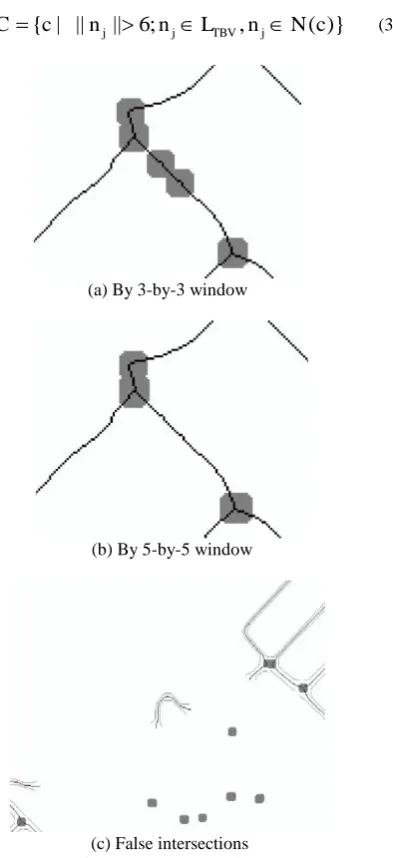
Taking a 5-by-5 window centered at a pixel of LTBV, and if there are more than 7 line pixels within the window the pixel is taken as a intersection point. Figure 4 (a) shows the wrong intersection s using a window of 3-by-3 pixels, and Figure 4 (b) shows the correct intersection s using a window of 5-by-5.
{ | ||
j|| 6;
j TBV,
j( )}
C
c
n
n
L
n
N c
(3)(a) By 3-by-3 window
(b) By 5-by-5 window
(c) False intersections Figure 4 Intersection detection
2.4 Road Network
Road network requires a connective diagram of the road lines. The algorithm breaks the initial optional lines near the intersections for sake of validation. However the initial lines can help to connect the broken LVAL. That is, the LVAL lines are
made grow along their initial TBV lines to the associated intersections.
Firstly, the road can only grow to the valid intersections, not empty intersection. If there are empty roads which does not deleted in the former stages the empty roads are not permitted to grow. Thus there are three functions in road growing.
2.4.1 Intersection validation: Obviously, intersection is the
key element in road growing. The intersections are detected using LTBV, not LVAL, because only LTBV are connected at the intersections. However this will cause some empty intersections because they had been connected to the deleted central lines, like that in Figure 4 (c). Therefore, the intersections without LVAL will be removed, which can be explained by equation (4). A neighbourhood is defined for an intersection and if there is no LVAL, pixel detected within, it is an empty intersection.
{ |
,
( )
},
val val val
C
c c
C N c
L
C
C
(4)
After that, all the intersections remained have some LVAL nearby,
although they don't touch each other but in practical world they do. In another word, the LVALs are virtually connected to the intersections.
2.4.2 Road growing: Road central line is broken near the
associated intersection. The objective of growing is to make the line reach out to the proper intersection. As we introduced before, the central line is single pixel wide, so the terminals (referred as ends) can be easily found. The growing starts from both ends of a LVAL. and stops within a limited length at the nearby intersection. To reasonably grow, the LTBV is used as the guidance for the corresponding LVAL. As a result, the grown LVAL recovers the whole path of the corresponding LTBV.
The implementation is described by equation (5). Growing Gk(ek) from an end ek is an iterative operation that in the nearest 3-by-3 neighbourhood of the current end, find its initial TBV line pixel g which does not neighbour to any intersection. If such a pixel is exist, update it as the current end and redo the searching and updating.
( )
( ) { |
,
,
( ),
,
}
k k k k TBV
val val val
G e G e g g L
g L n N g n L n C
(5)until
g g
0,
0
L
TBV,
g
0
L
val,
g
0
C
val.2.4.3 Recall the grown sectors: As we noticed from Figure
4(c), there are some roads lines that are not close to any intersection in a certain neighbourhood. They are parts of the non-validated roads, but remained since there are some blocks nearby. We employ a secondary central line validation to remove these lines and the associated sides by an similar growing operation.
that the end is empty. If both ends are empty the central lines is empty, just like the ones in Figure 4(c). For lines that having only one empty end, the grown pixels are cancelled using inverse growing, called recalling. For empty line, both the central line and the associated side are deleted.
As last, there are central lines and sides remained for the actual detected roads. To generate the continuous network, the road sides also grow along their relevant hulls in a similar way with the central line growing.
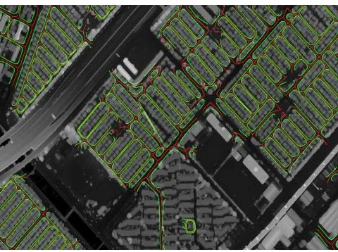
Figure 5 shows the road superimposed on the DSM with central lines in red, and the road sides in green. The road planes are not displayed, which are filled within the corresponding sides.
Figure 5 Road lines and the original DSM
3. CONCLUSIONS
There is no doubting that the road network extraction is important for GIS applications, urban planning, and remote sensing studies, and has been widely studied for many years. We present our method using high resolution DSM as the single data source and generating the road network of urban area quickly by all element road model and reasoning. Our main contributions are as follows.
1. We propose a technique which generates block and road in a coupling way. Block and road elements are extracted synchronously. The road lines are inherent continuous.
2. We propose a road network model including both line and area, represented by road central line, road side, and intersection. They are sufficient, self-contained and spatial relevant, and can be used in reasoning.
3. We present a cross validating method for the three element road model, to remove the false intersections, false branches of the central lines. Both the removal of the false detections and the growing of the road lines are induced according to the possible elements and the algorithm is avoid of blind searching.
ACKNOWLEDGEMENTS
Acknowledgements to the supports of the Chinese National Natural Science Foundation (NSFC no.41371331) and PASCO Corporation, Japan.
REFERENCES
Baumgartner A., Steger C., Mayer H., Eckstein W., 1997, Multi-resolution, semantic objects, and context for road extraction, Semantic Modeling for the Acquisition of Topographic Information from Images and Maps, Basel, pp. 140-156.
Baumgartner A., Steger C., Mayer H., Eckstein W., Ebner H., 1999, Automatic Road Extraction Based on Multi-Scale, Grouping, and Context, Photogrammetric Engineering & Remote Sensing, 65(7), pp. 777-785.
Clode S. P., Zelniker E. E., Kootsookos P. J., Clarkson I. V. L., 2004, A phase coded disk approach to thick curvilinear line detection, in Proc. 7th Eur. Signal Processing Conf., Vienna, Austria, pp.1147-1150.
Doucette P., Agouris P., Stefanidis A., Musavi M., 2001, Self-organised clustering for road extraction in classified imagery, ISPRS Journal of, Photogrammetry & Remote Sensing, 55, pp. 347-358.
Doucette P., Agouris P., Stefanidis A., 2004, Automated Road Extraction from High Resolution Multispectral Imagery, Photogrammetric Engineering & Remote Sensing, 70(12), pp. 1405-1416.
Grote A., Heipke C., Rottensteiner F., 2012, Road Network Extraction in Suburban Areas, The Photogrammetric Record, 27(137), pp. 8-28.
Herumurti D., Uchimura K., Koutaki G., Uemura T., 2013, Urban Road Extraction based on Hough Transform and Region Growing, The 19th Korea -Japan Joint Workshop on Frontiers of Computer Vision,Incheon, South Korea, pp. 220-224.
Hu X., Tao C. V., Hu Y., 2004, Automatic Road Extraction from Dense Urban Area by Integrated Processing of High Resolution Imagery and LiDAR Data, The International Archives of the Photogrammetry, Remote Sensing and Spatial Information Sciences, Istanbul, Turkey. Vol. XXXV, Part B3, pp. 288-292.
Hinz S., Baumgartner A., 2003, Automatic extraction of urban road networks from multi-view aerial imagery, ISPRS Journal of Photogrammetry & Remote Sensing 58, pp. 83-98.
Jung W., Kim W., Youn J., Bethel J., 2006, Automatic Urban Road Extraction From Digital Surface Model And Aerial Imagery, ASPRS 2006 Annual Conference, Reno, Nevada, pp.654-663.
Lu B., Ku Y., Wang H., 2009, Automatic Road Extraction Method Based on Level Set and Shape Analysis, Second International Conference on Intelligent Computation Technology and Automation ICICTA, vol. 3, pp.511-514.
Lu P., Du K., Yu W., Wang R., Deng Y., and Balz T., 2014, A New Region Growing-Based Method for Road Network Extraction and Its Application on Different Resolution SAR Images, IEEE Journal of Selected Topics in Applied Earth Observations and Remote Sensing, 7(12), pp.4772-4783.
Normalized Cuts and Level Set Methods, International Journal of Computer Applications, 18(7), pp. 10-16.
Ravanbakhsh M., Heipke C., Pakzad K., 2008, Extraction of Road Junction Islands from High Resolution Aerial Imagery Using Level Sets, The International Archives of the Photogrammetry, Remote Sensing and Spatial Information Sciences, Beijing, China, Vol. XXXVII. Part B3a. pp. 131-138.
Stolpe M., Bhaduri K., Das K., Morik K., 2013, Urban Road Network Extraction Based on Zebra Crossing Detection From a Very High Resolution RGB Aerial Image and DSM Data, International Conference on Signal-Image Technology & Internet-Based Systems, Kyoto, Japan, 8190(7), pp. 79-84.
Wiedemann, C., Ebner H., 2000, Automatic Completion and Evaluation of Road Networks, International Archives of Photogrammetry and Remote Sensing, Amsterdam, The Netherland, Vol. XXXIII, Part B3, pp. 979-986.
Zhang Q., Couloigner I., 2007, Accurate Centerline Detection and Line Width Estimation of Thick Lines Using the Radon Transform, IEEE Transactions On Image Processing, 16(2), pp. 310-316.